MODIFYING THE HAFLER DH-100
LET ME TELL YOU from the beginning that I found the Hafler DH-100 preamp to be well worth the price, and I recommend it if your system is on a budget. The kit is easy to build and you can improve it with some inexpensive modifications.
Even for the inveterate scratch builder, the kit is a good investment.
It has the resale value of a brand name preamp and has quite a collection of parts. The kit also includes a steel case that provides good magnet ic and electrostatic shielding, a number of polypropylene and polycarbonate capacitors, Alps switches and a quiet, simple regulated power supply.
The circuit is built on a glass epoxy board with film caps and one percent metal film resistors. I was less im pressed with the integrated circuits (ICs), but they are socketed and I changed them. The two channels of the volume control have slightly different tracking and it would be useful to upgrade this potentiometer, but I didn't care to spend the extra money.
Perhaps the Hafler Company came to the same conclusion.
In April of 1984, I bought the pre amp (and later a DH-220 power amp) through the mail from The Sound Seller! (see Source List). I chose this outlet solely on the basis of price, and they were friendly and provided quick service.
I encourage anyone with the desire, regardless of inexperience, to build a Hafler or Heath kit. The DH-100 is a good first project because it comes with most of the parts preassembled and tested. The operations left to the home builder are unlikely to cause damage from a slow soldering technique.
The DH-100's manual is well writ ten and illustrated. It guides the builder through the assembly procedure without confusion. When I completed this kit I had the sometimes elusive pleasure of having a project work correctly the first time.
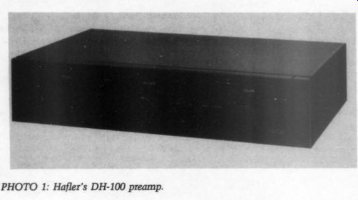
PHOTO 1: Hafler’s DH-100 preamp.
I enjoy 'ritually purifying' a device by second guessing the designer, and upgrading or removing parts. I al lowed the DH-100 kit to age for several months while I evaluated its performance. If anything was going to fail, I wanted it to do so before I voided the warranty. The David Hafler Company explicitly states in their assembly manual that any modification of the preamp may invalidate the warranty.
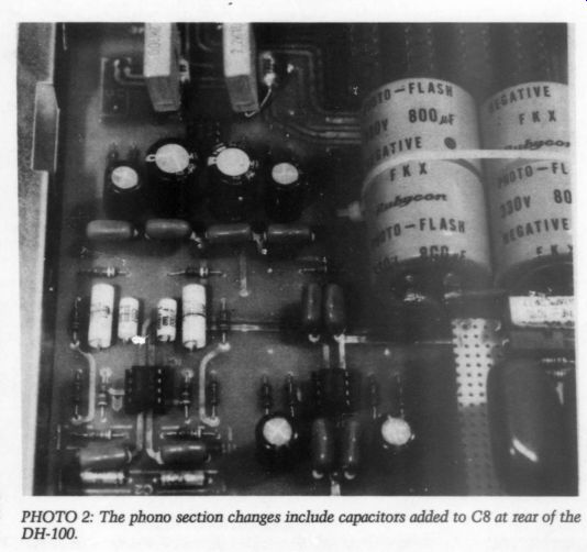
PHOTO 2: The phono section changes include capacitors added to C8 at rear of the DH-100.
Integrated Circuits
The DH-100, a relatively simple pre amp, relies on two ICs in the phono section to produce 33dB of gain at 1kHz (see Fig. 1 and Photo 2). At the phono input stage I substituted a Signetics NE5532 for IC1, which has a 28 percent faster slew rate than the stock LM833. The NE5532 has a 9V/ us rate compared to 7V/us for the LM833.
IC3 provides 20dB of gain in the line amplifier. It receives the phono section's output and all other inputs.
The stock DH-100 had a higher back ground noise than my previous pre amp, a discrete Nikko. ICs 2, 3 and 4 are Texas Instruments TL082s, which are a higher noise version of the ubiquitous TL072. At the suggestion of a Hafler engineer I substituted NE5532s at these positions. The NE5532 has much less noise, a higher output drive capability and the same pin configuration as the TL082. Al though the above modifications will present no problems to your sound system, if you find you prefer the TL084s, you can always reinstall them.
Coupling Caps
My next modification, removing most of the inter-stage coupling caps, is a more serious step, but provides audibly better transient response and cleaner sound. If you make these changes you must be careful using the preamp. So modified, it generates a destructive, woofer-bottoming thump at turn-on, which is faithfully passed by the nearly direct-coupled circuit. The DH-100 is not unique in this, however.
If you turn on your preamp before your power amp, and off after the power amp you will have only power outages and small children to worry about. A muting circuit, such as the one Robert Ballard describes in TAA 1/85, p. 38, will effectively bypass the speakers for the first few seconds after start-up. Also, you should turn the volume control down when switching between sources, because the preamp now passes sharp wave forms (clicks) well.
Rapidly moving the volume or balance control after removing the coupling caps will cause the preamp to produce a momentary DC offset, which displaces the speaker cones.
This phenomenon is unnoticeable with normal control movement, and is smaller than the DC offsets the power supply of the Hafler DH-220 generates when turned off. You may feel more comfortable by adding caps with lower dielectric absorption factors in parallel with the DH-100's polycarbonate types instead of removing the coupling caps. But, I believe the best capacitor is none at all.
After checking that my turntable had no switch on its output leads which could generate a transient spike, I replaced C1 (101) with double leads of wire from a Mogami 2477 mike cable. While I had my Technics turntable apart, I changed its output cables to Mogami also, but heard no difference.
Series capacitors interact to lower effective capacitance values. Note that the next caps, C7 (107), with a value of 2.2uF, and C8 (108), with a value of 1.0uF, are in series and have…
Figs 2a-c
…an equivalent value of 0.687 uF. This lower capacitance has a narrower bandwidth than either cap would have by itself, which slightly degrades the phase response and diminishes the circuit's ability to pass low frequencies. Consequently, I removed C7 (107) at the output of the phono section. These caps are duplicated by C8 (108) for all functions except the signal sent to the tape output.
Blocking caps for a tape deck need not be put in a position which affects phono playback. If you wish to provide DC blocking within the preamp for the tape loop, place C1 (101) in series between R12 (112), and J9, J10 respectively. Due to the capacitor's series interaction, I feel it is better to solder C1 (101) inside the tape deck, paralleling (and probably upgrading) the deck's existent caps.
The C8 and 108 pair provide DC blocking for the preamp's main amplification section. Although I left them in position, I paralleled them with the 2.2uF caps I removed from C7 (107) to broaden the bandwidth of this coupling stage. I also added 0.001uF polystyrene caps here for good measure, following Marsh and Jung's advice (Audio February and March 1980) who say that using a group of caps of decreasing value is more effective for reducing dielectric absorption than a single cap of an equivalent value.
The signal encounters C11 and C111 just before the balance control, so I replaced them with sections of OFHC (oxygen free high conductivity) wire. I also jumpered C15 (115), which follow the tone controls, al though you should not do this if you eliminate the tone controls.
Tone Control Bypass
If you wish to delete the tone control stage, remove R18 (118) and solder an OFHC lead from each balance pot's middle lug to the hot lug of each out put jack. This pot's front section is the right channel; the rear one is the left. Leave the output jack's lead to the circuit board intact, since it connects to the muting circuit. If you do bypass the tone control, remove C15 and C115. If you leave them connected and move the controls off their center detent, a dangerous low frequency oscillation results.
Even with the tone controls re moved I measured DC offsets of 64mV and 42mV from the modified ...
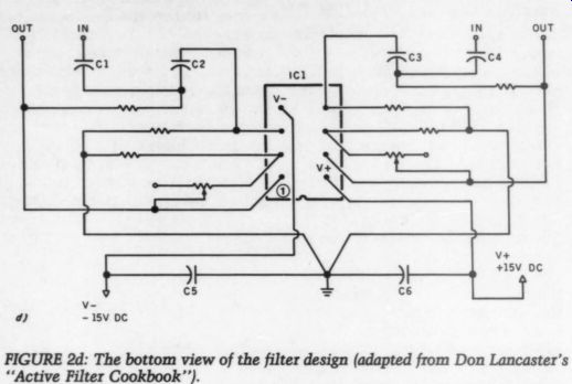
FIGURE 2d: The bottom view of the filter design (adapted from Don Lancaster's
“Active Filter Cookbook ”).
... preamp's outputs, but I accept the DC offset as the price for deleting the signal path caps, and treat this problem at the input of the power amplifier. Different 5532 chips have different amounts of offset. I finally found one with only 7mV of offset.
Each system component should have protection from incoming DC.
In the DH-100 this is provided by C8 (108). In the Hafler DH-220, DC is blocked by a 2.0xF cap in series with the input. I used C11 (111), left over from the “purification ” of the preamp, to bypass the input caps of the DH-220, increasing its bandwidth to match the preamp.
Infrasonic Filter
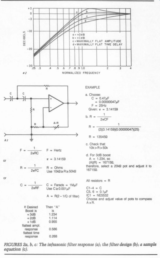
To correct the low frequency rolloff of my low-Q woofers, and to add an infrasonic filter, I used an adaptation of a second-order high-pass filter (Fig. 2b and c and Photo 3) as described by Don Lancaster in his Active-Filter Cookbook (Sams).2 By using a 10-turn trimpot in place of the single resistor which controls the Q of the filter, I can adjust the filter's behavior near resonance to be under-damped, and so add a bass boost to correct the speaker's over damped rolloff. When you compensate for a rolloff with a boost in an otherwise minimum-phase system you improve the time-domain response.
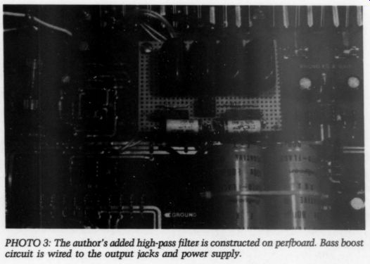
PHOTO 3: The author's added high-pass filter is constructed on perfboard.
Bass boost circuit is wired to the output jacks and power supply.
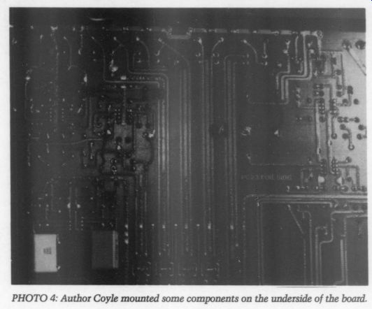
--- Photo 4
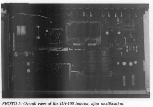
PHOTO 5: Overall view of the DH-100 interior, after modification.
I consulted the frequency/amplitude graph for my speakers, and then selected the filter's - 3dB point to be at 25Hz, with a 3dB boost in the lowest range of the speakers, from 30-60Hz (Fig. 2a). The filter is inserted after the preamp's circuit board, and before the output jack.
Although I have taken a step back ward by adding two caps and an op amp in the signal path, by using quality caps and a NE5532 IC I have minimized the degradation. If you are happy enough to have flat amplitude speakers and do not want an infra sonic filter, you should omit this stage.
Power Supply
I increased the power supply filtering with a pair of Rubycon 800uF, 330V photoflash caps from the Electronic Supermarket. The 800s were available as unused surplus at a good price. (See Photo 3.) Photoflash caps have low inductance and are able to
discharge rapidly. I also added two
0.1uF stacked film caps in parallel with C22, C23, C24 and C25. Here the strategy was not to bypass, but to add a small low-inductance, local power reservoir.
I must compliment and thank the Hafler organization for their responsive service. While performing some pre-start-up checks on the preamp, I noticed a low voltage in the power supply. I wrote to Hafler and within ten days I received a replacement transformer, with the explanation that my kit had come with a European type transformer.
Listening
The preamp now sounds perceivably better; the transients have a sharper attack. A layer of veiling seems to have been removed. While the turn on procedure of the preamp is bothersome, the benefits are worth the trouble. My friend Bruce Madden and I compared his Crown IC-150 with the Hafler and agreed that the Hafler sounded cleaner and sharper. The bass was stronger. While I acknowledge that the DH-100 is not going to be mistaken for a $1500 preamp, it is worth its price. O SOURCES
1. The Sound Seller 1706 Main St. Marinette, WI 02224
. Old Colony Sound Labs PO Box 243 Peterborough, NH 03458
. Electronic Supermarket PO Box 988 Lynnfield, MA 01940
The David Hafler Co. comments Since the design philosophy of this unit is to provide a simple and care fully engineered circuit for the best performance at low cost, we have serious reservations about several of Mr. Coyle's modifications; two in particular require specific comment.
In an attempt to reduce the DH-100's inherent noise level, Mr. Coyle suggests replacing the TL0082 devices with the 5532. Readers should be aware that such a change will detrimentally alter three of the preamp's specifications, namely the
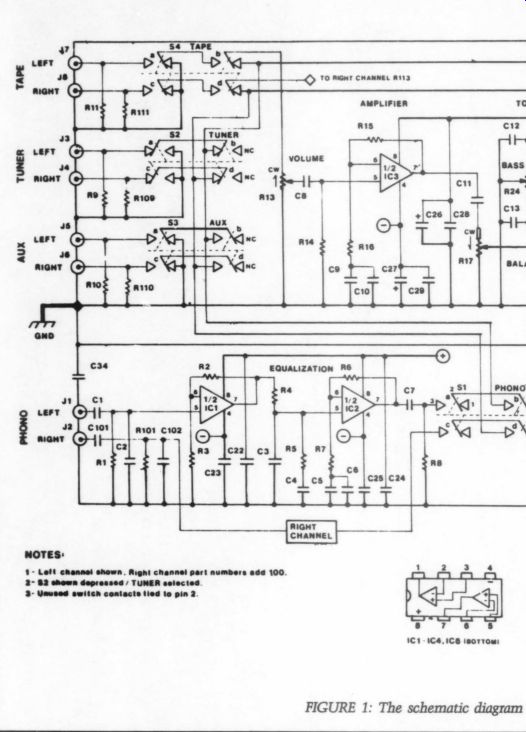
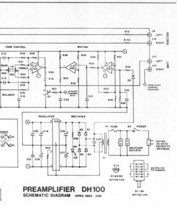
--- FIGURE 1: The schematic diagram of the DH-100. (Reprinted with permission.)
SCHEMATIC DIAGRAM APRIL1983 JHN
NOTES:
1- Left channel shown. Right channel part numbers add 100 2- 82 shown depressed / TUNER selected 3- Unused switch contacts tied to pin 2
RIAA characteristic, the high frequency THD and the gain bandwidth product. All three result from the widely varying input impedance of the 5532, which at its best is far too low for these circuit locations.
Mr. Coyle also suggests removing C11 and C111 in the line amplifier section. We caution that the offset voltage from IC3 can, over time, cause damage to the film element in the balance control, R17, especially if it is kept primarily in one position.
We are sympathetic with the desire to improve noise performance. One can only hope that a quiet, economical FET op amp will soon be avail able. In the meantime, we urge experimenters to proceed carefully, in the spirit of the more thoughtful modification articles that have appeared in past issues of TAA. Our thanks to Mr. Coyle for his support of our Model 100.
Author Coyle replies:
DH-100.
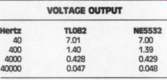
Hafler asserts the 5532 “will detrimentally alter...the RIAA characteristic, the high frequency THD and the gain bandwidth product. ” The empirical evidence does not support this statement. In the first test I performed, the signal was fed through the DH-100 phono input with a TL082 and then a 5532 in the IC2 socket. The results are as follows:
TL082 7.01 1.40
0.428
0.047
Obviously, there is no RIAA difference.
I next measured the THD in both channels. The results show the 5532 to be the better chip at high frequencies. In this test the output is held constant at 2.0V, while varying the signal frequency.
----------------
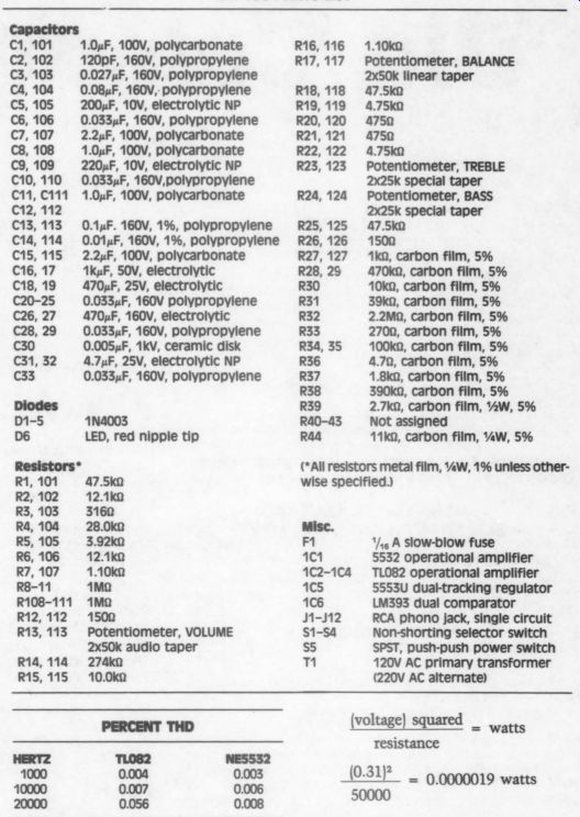
DH-100 PARTS LIST
Capacitors C1, 101 C2, 102 C3, 103 C4, 104 CS, 105 C6, 106 C7, 107 C8, 108 C9, 109 C10, 110 C11, C111 C12, 112 C13, 113 C14, 14 C15, 115 C16, 17 C18, 19 C20-25 C26, 27 C28, 29 C30 C31, 32 C33 1.0¢F, 100V, polycarbonate 120pF, 160V, polypropylene
0.027uF, 160V, polypropylene
0.08xF, 160V, polypropylene 200uF, 10V, electrolytic NP
0.033yF, 160V, polypropylene 2.2uF, 100V, polycarbonate 1.0xF, 100V, polycarbonate 220 uF, 10V, electrolytic NP
0.033,F, 160V, polypropylene 1.0xF, 100V, polycarbonate
0.14F. 160V, 1%, polypropylene
0.014F, 160V, 1%, polypropylene 2.2yF, 100V, polycarbonate 1kuF, 50V, electrolytic 470uF, 25V, electrolytic
0.033.F, 160V polypropylene 470xF, 160V, electrolytic
0.0334F, 160V, polypropylene
0.005xF, 1kV, ceramic disk 4.7uF, 25V, electrolytic NP
0.0334F, 160V, polypropylene 1N4003 LED, red nipple tip R1, 101 R2, 102 R3, 103 R4, 104 RS, 105 R6, 106 R7, 107 R8-11 R108-111 R12, 112 R13, 113 47.5k0 12.1ke 3160 28.0kn 3.92ko 12.1k2 1.10k0 1M M-OHM 1500 Potentiometer, VOLUME 2x50k audio taper 274 k-ohm 10.0ke R14, 114 R15, 115 R16, 116 R17, 117 1.10ka
Potentiometer, BALANCE 2x50k linear taper 47.5k0 4.75 k-ohm 4750
4.75 k-ohm Potentiometer, TREBLE 2x25k special taper
Potentiometer, BASS 2x25k special taper 47.5k0 1500 1k, carbon film, 5% 470 k-ohm, carbon film, 5% 10 k-ohm, carbon film, 5% 39 k-ohm, carbon film, 5% 2.2 M-ohm, carbon film, 5% 2704, carbon film, 5% 100ke, carbon film, 5% 4.7 , carbon film, 5% 1.8 k-ohm, carbon film, 5% 390k, carbon film, 5% 2.7 k-ohm, carbon film, %W, 5% Not assigned 11 k-ohm, carbon film, %W, 5% R18, 118 R19, 119 R20, 120 R21, 121 R22, 122 R23, 123 R24, 124 R25, 125 R26, 126 R27, 127 R28, 29 R30 R31 R32 R33 R34, 35 R36 R37 R38 R39 R40-43 R44 ( All resistors metal film, 0.5 W, 1% unless other wise specified.)
Misc.
F1 1/46 A slow-blow fuse 1C1 5532 operational amplifier 1C2-1C4 TL082 operational amplifier 1C5 5553U dual-tracking regulator 1C6 LM393 dual comparator 1-112 RCA phono jack, single circuit
$1-54 Non-shorting selector switch SS SPST, push-push power switch
120V AC primary transformer (220V AC alternate)
-------------
HERTZ 1000 10000 20000 TL082
0.004
0.007
0.056
NES5532
0.003
0.006
0.008
-----------
Notice at 20kHz it is the TL082 which has seven times the distortion of the 5532 (though still an insignificant amount). This is consistent with the higher open loop gain of the 5532 at 20kHz compared to the TL082, contrary to Hafler's third assertion.
Responding to Hafler's concern that the removal of C11 and C111 may, in time, damage the 50 k-ohm balance pots I measured a 31mV off set on one 5532 in IC3, and 7mV on a different 5532 in the same position.
Taking the worst case, 31 mV, and multiplying by a safety factor of 10, Ohm's law states that the power dissipated by the pot will be:
Surely, this is not too much power for the pot to dissipate indefinitely.
Readers who perform the cap modification should verify that their 5532 produces a similarly low offset. This offset does require a DC blocking cap at the power amplifiers input. As to Hafler's concern about the 5532's “low ” input impedance (typically 300k open loop), you may change R14 and R114 to 82k.
Hafler hopes that someday “a quiet, economical FET op amp will be available, ” in the meantime I refer them to the TL072 which is 2.8dB quieter than the TL082.
MODIFYING THE DH-100
I humbly suggest that my article is not so far from “the spirit of the more thoughtful modification articles that have appeared in past issues of TAA ” as Hafler may fear. I re-warn readers who remove the caps that it is essential to switch the preamp on before and off after the power amplifier.
I am grateful for the time and help of Mr. Ron Kay, and for the use of the University of New Mexico's Keller Hall recording room. The test instruments include a Krohn-Hite Model 6900A auto-level, auto-null distortion analyzer, and a Krohn-Hite Model 4500A ultra-low distortion signal generator. The test setup details are available to those who wish to write me in care of TAA.
By Daniel Patrick Coyle
----
Also see:
Yamaha CDX 1120 CD player (Jan. 1990)