IMPROVING LOGICAL SYSTEMS 1081 ANALYZER
Are YEARS OF setting my stereo equalizer with a test tape and sound level meter (a tedious procedure at best), I purchased a Logical Systems 1081 real time analyzer (Photos 1-2). After I assembled the kit, however, I found it did not realize its full performance potential, and the suggested phantom power supply did not function with the microphone I built.
A Unique Voice
Rather than use a pink noise generator for a test signal, the 1081 provides a digitally-synthesized “voice.” ICS, a 555 timer, generates pulses which drive IC5, a 12-bit binary counter.
Ten of the 12 bits drive a filter circuit, such as R91-C38-R92, which produces a component in the “voice ” corresponding to one of the octaves of interest.
The remaining two bits are not used. Since each bit in a binary count changes twice as often as the next more significant bit, using the least significant bit to drive the lowest octave filter (with each more significant bit driving the next higher octave) will provide the 3dB per octave rolloff pink noise characteristic. This special design allows for octave-by-octave output fine-tuning.
Performance Improvements
When I started calibrating the analyzer's output section, I found the supplied calibration resistors would not give a flat (straight-line) display.
A friend of mine assembled a 1081 kit and obtained the same result, so I was not too surprised.
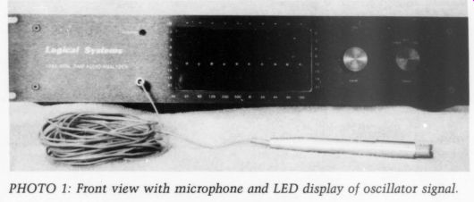
PHOTO 1: Front view with microphone and LED display of oscillator signal.
I used a White Line pink noise generator to verify the proper operation of the input and analyzer display sections, and I replaced the calibration resistors with 1M trim pots. Next, I soldered 3/4" wire stand-offs on thumb wheel-type pots (Radio Shack #271 229), which were too large and resulted in a rather messy installation.
Should you perform this modification, consider using Bourns 15-turn pots (Jameco #43p-1M). They should fit well if you install them in staggered heights. Set each pot to its mid point and plug in the 1081.
With the selector on “voice,” set the input level control so the 16k column has two adjacent LEDs (light emitting diodes) lit equally (such as -9dB and - 12dB). Now, set the 8k pot to obtain the same result with the 8k column, and continue with each successively lower octave down to 32Hz. Setting one octave will upset the octaves adjacent to it, so you'll ...
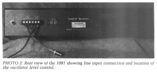
PHOTO 2: Rear view of the 1081 showing line input connection and location
of the oscillator level control.
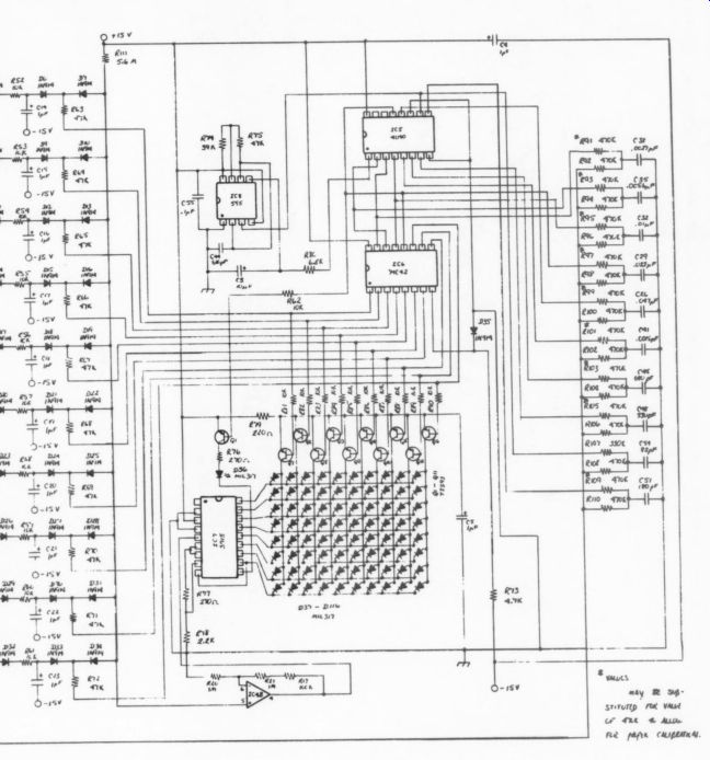
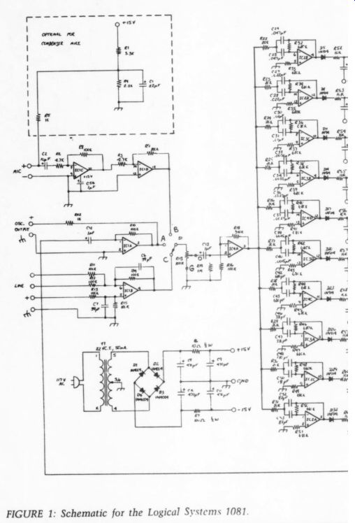
--- Fig. 1
... have to repeat the entire process several times.
The lights from the lower octaves bounce from one level to the next, but you can set these octaves so the two LEDs light for equal amounts of time. The voice output level is much higher than necessary, and since a level control is useful, I installed a 10K Allen-Bradley pot (Jameco #CMU1031) in the upper left corner of the rear panel.
Wire this pot for maximum resistance in the CW position, and jumper the unused terminal to the wiper.
Remove R10 and run a twisted pair of wires from the pot to replace R10.
Finally, replace the red and black twisted pair running to the front pan el microphone jack with a shielded wire.
If you do not wish to install a phantom power source for the micro phone, your internal modifications are finished. The stereo RCA input jacks have sufficiently flat response so you can visually monitor music, but to get the flattest response with line-level signals (such as the sound level meter or preamp output), connect the source to the balanced line inputs; ground to the ‘+' input and “hot” to a line input.
Phantom Power
The analyzer's unregulated power supply contains too much ripple to use with the indicated phantom power circuit. The provided board space is adequate for the following changes:
R1-10k
R5-2k
C1-1000 uF , 15V
R4-1W
6.2V , zener diode (Radio Shack #276-561).
Using these parts will provide a low noise DC bias on the microphone line. Now, you can reassemble the analyzer for the last (you hope) time.
Phantom-Powered Microphone
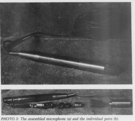
When you construct the microphone, make sure the element is acoustically exposed yet completely electrically shielded.
I met these criteria by placing the element at the end of an aluminum marking pen housing (Photo 3), and surrounding it with a shield which I cut and soldered from a piece of stain less steel filter mesh. (Stainless steel requires a special solder and flux, found at many hardware stores. You can also use brass screen with more conventional solder and flux.) Ground the screen, microphone housing and capsule housing to the cable shield. I wired the capacitors and resistor by twisting their leads and soldering them after I physically arranged the components in the housing.
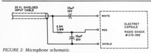
FIGURE 2: Microphone schematic.
Using the Analyzer
Connect the analyzer as described in the owner's manual, but do not power up your system yet. If you use a directional mike, place it at your optimum listening position and aim it at a point midway between your speakers. If you use a sound level meter with an output jack, connect the jack to the analyzer's line input (as described earlier). Select the proper input on the analyzer, set the oscillator output level control fully CCW (minimum), select the correct input at your preamp, by-pass all tone controls (equalizer, loudness compensation, and so on), and turn on your system.
You shouldn't hear a thing, but the analyzer should display room noises.
Set the input level control on the analyzer so room noises are just be low the display's threshold. Set all volume and gain controls to positions normal for listening, and increase the analyzer output until the 'voice' gives about a -12dB display.
You may find that repositioning the active speaker will yield a smoother (but not necessarily flatter) bass response. Smoothest response is your goal at this point, and you can easily handle changes covering several octaves with active equalization.
Next, examine the octaves around the woofer-midrange crossover frequency and set the midrange level control for smoothest response in this region. Use the tweeter level control and repeat the process for the mid range-tweeter crossover frequency.
Reconnect the oscillator output to the other channel and repeat the procedure using the other speaker. If you have power amplifier gain controls, set them so both channels give about the same level during this step.
Setting the Equalizer
If you wish to use loudness compensation, set your volume control to the loudest position you normally use.
Place loudness compensation and your equalizer in the signal path, and set the oscillator level for a reasonable voice level. (This means loud enough to eliminate ambient noises, but not loud enough to damage your hearing or speakers.) Set the equalizer sliders for the flattest possible response, using two adjacent rows of LEDs as you did when calibrating the analyzer.
If you use the Radio Shack sound level meter, you cannot set the 16k slider, so set the 8k and 30Hz levels 3dB lower to correlate with the response chart for the microphone in the meter. If you use the phantom powered microphone, increase the 30Hz level 3dB and reduce the 16K level 3dB. Without changing any level controls, repeat this procedure for the other channel. If the same two rows of LEDs light, the balance between channels should be identical.
When you finish, the pattern of your equalizer sliders will not resemble anything seen in stereo stores or advertisements. Due to the overlap ping effects of adjacent sliders, the actual frequency response change (if monitored at the preamp outputs) is less drastic than the sliders' pattern would suggest.
Conclusion
If you thoroughly enjoyed this procedure and would like to repeat it in the near future, pack up your micro phones and cables, and sit back listen to some music.
Otherwise, record all slider and level control positions. I have ob served well-meaning friends who can 'smooth out’ your frequency response and restore “classic ” curves to your equalizer in about 11 seconds.
A wife, when dusting, can provide you with ‘clean' sound in eight seconds, while a four year old child can move about three sliders per second.
ABOUT THE AUTHOR
Terry Smith's electronics background includes training in college and while working as an industrial electrician. He is currently a department maintenance manager, and en joys all music, particularly Dave Grusin, the Manheim Steamroller, and the Canadian Brass.
----
Also see: