Depts and Regular Columns
- Intro
- AUDIO AIDS, By S. Vermette, Richard Painter, Gary Galo, L. Rusch and William Capelle
- CLASSIC CIRCUITRY A VINTAGE INVERTER, Courtesy of Don Burgess
- BOOK REVIEW, Reviewed by Bill Ruck
- SHOWCASE MOSFET MOBILE AMP, By Randolph Vikan
- JUST LOOKING
- LETTERS
Intro
Norman H. Crowhurst, one of audio's most distinguished authors, appears again in our pages just one year after we reprinted his classic 1957 amplifier distortion article. The text (here) is vintage Crowhurst in his unique tutorial/ construction style and is the first of a series on pulse modulated amplifiers.
More impressive details of H.J. Heckert's monster 500W/channel (4 ohm) power amplifier are further unveiled starting (here).
Jan Didden, our enthusiastic Dutch contributor, has pushed the idea of a fast, quality preamp power supply a bit further along, as detailed (here).
If you are one of those who bought a 1081 Real-Time Analyzer from the now defunct Logical Systems Co., you probably don't consider it lucky. Neither did Terry Smith until he decided the unit could be fixed. His detailed suggestions for rejuvenating and improving the device begins (here).
Contributing Editor Erno Borbely completes his outstanding moving-coil preamp and a highly sophisticated power supply for it beginning (here). Later this year we hope to publish a comparative evaluation, which will include several other contenders, as well.
We are especially pleased to publish some viewpoints and opinions of a modest man of extraordinary skill and taste. John Dunkerley, one of Decca/London ’s recording engineers, invited editors of this magazine to visit a recording session of L'Orchestre Symphonique de Montreal and agreed to an interview. The result begins (here).
Just Looking
DB Systems has released the DB-1A-HL and DB-1B-HL, preamplifiers the maker says offer the performance of current DB systems, yet are less expensive and feature five instead of four inputs.
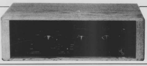
According to the manufacturer, the 1A has been optimized as a line-level amp and features extended high frequency response comparable to the DB-1A. Suggested retail price for the 1A-HL, including the DB-2A power supply, is $375. Options include tight-tracking, low-noise volume control (as used in DB-1B), gold-plated jacks, and a solid oak cabinet with 10.5 inch wide faceplate. These options are standard with the DB-1B-HL, which also features switch able loudness compensation that approximates the 50dB Robinson Dade Loudness Countour. Suggested retail price: $530. For further details, contact DB Systems, Main St., Rindge, NH 03461, (603) 899-5121.
Marchand Electronics, Inc. has released its new audio kits catalog. Featured products include the XMI electronic crossover network, the PM2 50W power amplifier module, the LN5 low noise phono preamp, the XP3 three-way amplifier, and an assortment of polystyrene capacitors and ICs. To receive your copy, contact Marchand Electronics, Inc., 1334 Robin Hood Lane, Webster, NY 14580, (716) 872-5578.
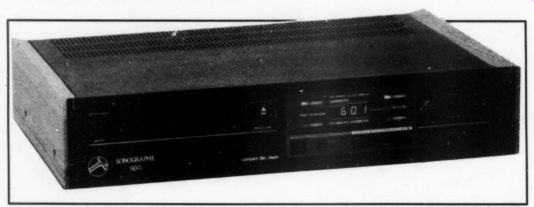
Conrad-Johnson Design, Inc. has introduced the Sonographe SD1 CD player. The SD1 features analog audio circuits designed by the manufacturer, and the final active filter is a discrete FET cir cuit coupled with a polypropylene capacitor to the final output. The player also features four-times oversampling and digital filtering. Separate digital-to analog converters for each channel are designed to eliminate phase shift be tween channels. Convenience features include programmable playback, pause, and forward and reverse search. Suggested retail price: $695. For more details, contact Conrad-Johnson Design, Inc., 1474 Pathfinder Lane, McLean, VA 22010, (703) 528-8650.
Audio-Technica US, Inc. has released its second CD player, the AT-CD20. Un like the AT-CD10, the new player features a full-function wireless remote control which duplicates all front panel controls. An LED on the front panel indicates when the player receives infrared commands from the remote control.
According to the manufacturer, the AT-CD20 utilizes a triple-beam laser system for increased tracking precision, plus an 88.2kHz sampling rate which the manufacturer says permits increased linearity and reduced distortion in the reproduced signal. The company also claims special sample-and-hold and error correction circuits further improve performance of less-than-perfect CDs. Suggested retail price: $399.95. For more details, contact Don Kirkendall or Rock Wehrmann at Audio-Technica US, Inc., 1221 Commerce Drive, Stow, OH 44224, (216) 686-2600.
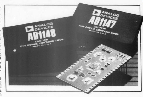
Analog Devices has released three new products: a 16-bit digital-to-analog converter (DAC), a monolithic voltage-to frequency (VFC) converter, and a 16-bit monolithic DAC. The AD1147 16-bit DAC is billed to be the first to provide an internal digital correction feature to eliminate manual trimming of initial offset and gain errors. Two 8-bit latched input DACs provide this correction through microprocessor control. The manufacturer says the AD1147 guarantees both differential and integral nonlinearity of +0.00076% maximum (+ 1/2LSB) which, according to the company, makes it the most ac curate hybrid DAC in the industry. A less expensive, less accurate (15-bits linear) version of the AD1147, the AD1148, is available with similar digital calibration capabilities. It features a separate data bus for the correction DACs. Suggested retail price: $152 (AD1147), $138 (AD1148). Analog Devices' AD651 synchronous VEC promises to guarantee +0.005% maximum nonlinearity at 1MHz full scale, while limiting maximum gain drift to +25ppm/°C at 500kHz full scale. The company claims both specifications guarantee better performance than other VFCs. Applications include process control, analytical and medical instrumentation, data acquisition, and frequency-to voltage conversion. Available in a 16-pin cerdip, the AD651 is specified for + 15V power supplies. Suggested retail price: $7.95/100 (Grade A), $15.60/100 (Grade B), $13.65/100 (Grade C). Analog Devices' AD569 is believed to be the industry's first monolithic DAC that guarantees 16 bits of monotonicity over its specified operating temperature ranges. It is also the first double-buffered DAC of its kind, allowing it to interface directly to an 8 or 16-bit data bus. It is designed for closed-loop process control, position servo application, or any application requiring the generation of high-precision analog signals.
The product is packaged in a 28-pin ceramic or 28-pin plastic DIP, while the converter operates from + 12V supplies. Suggested retail price: $19/100 (Grade JN), $24/100 (Grade KN), $28/100 (Grade AD), $37/100 (Grade BD), and $88.50/100 ( Grade SD). For complete information on each product, write to Analog Devices Literature Center, Shawmut Rd., Canton, MA, 02021.
Dolby Surround Sound and 16-bit digital time delay are the chief attractions of the AVD-700 digital surround sound processor from NEC Home Electronics (USA), Inc.
Contact East is offering a free, one year subscription to its tool and instrument catalog. The newest edition introduces 89 new items and features more than 5,000 products for assembling, installing, testing, and repairing electronic equipment.
Contact East's product line includes precision hand tools, tool kits, test instruments, soldering supplies, static control devices, and many hard-to-find items.
To receive your free catalog, write to Contact East, PO Box 786, No. Andover, MA 01845, or call 1-800-225-5370 (in Massachusetts, dial 1-617-682-2000).
According to the manufacturer, to provide delay without compromising fidelity, the AVD-700 uses the same 16-bit quantization and 44.1kHz sam pling rate responsible for CD sound quality. Signal-to-noise ratio is rated at 90dB, total harmonic distortion is less than 0.02%, and frequency response ranges from 10Hz to 20kHz within a tolerance of +0.5dB.
The AVD-700 features separate, in dependently-adjustable digital delay lines for left and right channels, plus four modes of surround sound: matrix, hall, creation, and Dolby. The product also offers inputs for five different audio video sources, and five additional audio only sources.
For pricing information and further details, contact NEC Home Electronics (USA) Inc., 1255 Michael Drive, Wood Dale, IL 60191, (312) 860-9500.
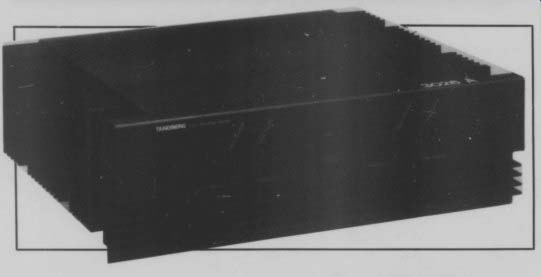
Tandberg ’s new TPA 3026A high-current stereo power amplifier is an off shoot of the company's top-of-the-line TPA 3016A. Its peak current rating is listed at 30A per channel, with power ratings of 150W per channel into 8 ohm speakers and 300W per channel into 4 ohm.
The manufacturer claims the new amp can play highly-dynamic music through drivers with difficult impedance characteristics.
Keys to this feature include a tightly regulated power supply with toroidal transformer and large storage capacitors, plus MOSFET output devices which are said to eliminate the need for signal degrading protection circuits.
The TPA 3026A is finished in matte black with optional rosewood end panels Author Bruce F. Elving of FM Station Atlas has announced the revised tenth edition of “FM Atlas and Station Directory. ” Nearly two years in the making, the latest edition is designed to make it easier for FM radio enthusiasts to tune in to their favorite sounds.
The book features 77 pages of FM maps showing exact station locations, call letters and frequencies, and directories arranged by frequency and geography. The directories offer full technical and programming data for nearly 5,000 FM stations in the US, Canada, and Mexico.
Other features include listings of stations with an SCA subcarrier, low-power FM translators, plus educational, public, religious, and commercial stations.
Revised editorial content questions the longevity of AM radio, Canada's stations which don't individually identify, and a look at what recent FCC changes might mean to listeners. Suggested retail price: $8.95 plus 55 cents postage. To order, write to FM Station Atlas, Bruce Elving, PO Box 24, Adolph, MN 55701.
[...] or 19 ” rack mounting adapters. Suggested retail price: $1,595.
For further information, contact Tandberg, Labriola Court, Armonk, NY 10504, (914) 273-9150.
Gold Aero has recently contracted with a major electron tube manufacturer to remanufacture the KT88 beam power tube to Gold Lion standards. The KT88 had been supplied to the US through M.O. Valve of Great Britain until production stopped on the Gold Lion tubes last year.
After being thoroughly tested by Gold Aero's engineering staff, pre-production samples were inserted in an Audio Research D250 mKII servo amplifier where, it is claimed, they performed superbly. For further information on the new KT88s, contact Ron Reznick, Gold Aero, 2129 Venice Blvd., Los Angeles, CA 90006, (213) 737-7070.

Technological Artisans (Tech Art) has developed a series of pre-assembled electronic “building blocks ” for high-tech creative designers. The modular components are de signed to assimilate into OEM systems. More than 20 different components are available for such functions as low-level and power amplification, mixing, switching, linear function generation, lissajous pattern generation, and circular sweep/polar to Cartesian conversion.
Multiple components can be easily interconnected with Tech Art's LASE BUS. With the building blocks, designers can have a system complete ly operational within a matter of hours.
For complete details, contact Diane Burley, Technological Artisans, 53 West 72nd St. (3G), New York, NY 10024, (212) 496-9807.
AD

NEW FROM HAFLER As an evolutionary development with revolutionary implications for amplifier evaluation standards, this latest David Hafler circuit may be the most important power amplifier event in recent years. Described as EXCE LINEAR, it demonstrates previously unattainable levels of amplitude, phase and transfer characteristic linearity. For the first time, an amplifier is so ac curate, it can be directly com pared with the classic zero distortion reference: a straight wire. In a differential arrangement the straight wire and the amplifier are fed the same signal, with the input signal to the amplifier adjusted for an overall gain of unity.
This subtracts the input from the output of the amplifier; the difference, or residual, is the total distortion content.
In this test the speaker reproduces only the distortion.
The test surpasses conventional measurements in its sensitivity and precision. The test is definitive with any program content- music, sine waves, white or pink noise. It justifies some unquantifiable 'golden ear' assessments of differing amplifier sounds.
Amplifiers which do not perform as well on this test are, quite simply, less accurate.
In a differential comparison with a straight wire the XL-280 is the first amplifier to achieve a null at all audio frequencies which taxes your perception. Its EX CELINEAR design reduces all distortions to inaudibility-even those which have not yet been identified or quantified. Over most of the audio band, the XL-280 achieves nulls of 60 dB or more.
Other amplifiers rarely exceed 40 dB.
and a new listening test for accuracy As delivered, the XL-280 has exemplary harmonic and inter modulation distortion specifications comparable to the current Hafler DH-220 amplifier. It includes a phase correcting circuit which enables individual adjustment for the differential null. This has been set at the factory for optimum interfacing with a 'standard' loudspeaker load. Different speaker designs present varying loads to the amplifier which can introduce minute phase and amplitude related variations. This is one reason why all amplifiers do not sound the same, and why the sound of any one may vary on different speakers.
For the purist, the XL-280 includes the capability for 'tweaking' each channel to optimally match (null with) your speaker.
This range of adjustment is entirely within the XL-280's printed specifications, and is of significance only to 'golden ears' But it can be performed without test instruments, with patience, in quiet surroundings. It does re quire very precise adjustment of the amplifier's input level. The procedure is described in the XL 280's manual, and we will sup ply details to those who request them. Comparing 'nulls' of other amplifier designs is sure to pro vide grist for erudite discussion.
The XL-280 appears similar to a DH-220, but is an inch wider. It retains the traditional Hafler full complementary circuit driving MOSFET outputs. It has J-FET input stages for lower distortion, lower noise, and improved thermal stability. We've eliminated the conventional input capacitor to re duce low frequency phase shift.

The output choke has vanished to improve high frequency phase characteristics, yet excellent stability has been retained. Overall feedback has been reduced about 30dB. This further reduces its al ready low TIM distortion. And you can switch to bridged mono operation when you need a real powerhouse.
But the biggest changes are to separate power supplies for each channel, and in the output stage.
Only the transformer is common to the two channels. Power supply capacitance is up 56%.
There are separate high and low voltage supplies on each channel.
And we've added another pair of the same rugged MOSFETs on each side. The results are improved channel separation and greatly increased power into low impedance loads. Evolutionary -- -yes. But of revolutionary significance. And the price goes up only $100! Check with your dealer Now.
XL-280 STATISTICS: Rated Power: 145 watts into 8 ohms, each channel, both channels driven, at less than 0.05% THD, 20-20 kHz, or 0.04% IM.
Power Output Capability: 400 watts continuous into 8 ohms in mono, 20-20 kHz.
180 watts each channel into 8 ohms, clipping @ 1 kHz.
200 watts each channel into 4 ohms, 0.1% THD, 20-20 kHz.
280 watts each channel into 4 ohms, clipping @1 kHz.
360 watts each channel into 2 ohms, clipping @ 1 kHz.
325 watts each channel into 1 ohm, clipping @ 1 kHz.
Frequency Response: 0.1 Hz to 500 kHz, +/-3 dB @ 1 watt.
Slew Rate: 75V/us; 10 kHz, 60 volts p-p square wave.
Damping Factor: >180, 20-20 kHz into 8 ohms.
Phase Shift: Less than 2 degree, 20-20 kHz.
Maximum Output Current: 20 amps RMS.
Crescent Boulevard Pennsauken, New Jersey 08109
609/662-6355
Audio Aids
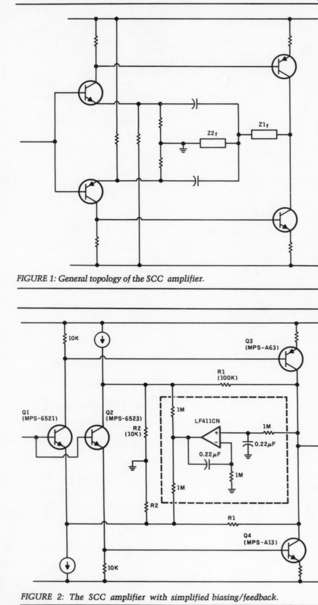
FIGURE 1: General topology of the SCC amplifier.
FIGURE 2: The SCC amplifier with simplified biasing/feedback.
SIMPLE BIASING SCC AMPLIFIER
The SCC (Symmetrical Complimentary Configuration) amplifier has many ad vantages, as attested to by Erno Borbely in his recent article in TAA (4/85).
When bipolar input transistors are used, however, the base-emitter voltage causes headaches to the designer in the biasing/feedback area (MOSFET transistors alleviate the problem). Extra components are needed (Fig. 1), presenting attendant complications.
In many cases, however, I find the simple configuration shown in Fig. 2 can be used instead. Resistors R2 affect both biasing and feedback, while the voltage divider consisting of the two R1 resistors gives a OV DC output (with matched resistors). Gain is the standard (R1+ R2)/R2 formula, which gives 20.8dB for the specific values shown. The SCC amplifier in Fig. 2 can thus be used for Borbely's RIAA-1 amplifier stage (TAA 4/85, Fig. 11, p. 12). There is, however, a small noise penalty due to the high value feedback resistors.
The servo amplifier, denoted by the dotted lines (Fig. 2), is optional, but I recommend it if low DC offset is required. The current sources feeding the emitter of both Q1 and Q2, however, are mandatory. You can do this easily with just a few components.
All in all, this is a low-cost, linear voltage amplifier with easy-to-find bipolar transistors.
S. VERMETTE
St. Angele de Laval, Quebec
THE PV-3 PLUS
HERE IS A SIMPLE modification for PV-3 owners that will produce dramatic results. After reading 'The Great Preamp Shootout’ (TAA 2/85), 1 purchased a Conrad-Johnson PV-3 demo and com pared it to my Vorhis Last PAS (TAA 4/82 and 5/82). I found the PV-3 had much more impact in the bass region, though I preferred the Vorhis PAS's smoother midrange. I then compared the PV-3 with a friend's PV-4, and I found the PV-4 had slightly better bass and smoother midrange. The difference was the PV-4 had half again as much filter capacitance, and polystyrene caps rather than silver mica in the phono section.
To remedy this, I obtained two 30uF 250V Solen caps which I soldered in
parallel with each of the 1uF caps (the large yellow caps you can see on the circuit board). Though the caps are large, they will fit in back of the circuit board.
I then added two small caps (.01uF 250V or greater) across the same film caps to extend the high frequency detail and dynamics.
To upgrade the phono section to PV-4 standards, I merely replaced four mica caps (small, thin, shiny caps marked 750pF and 2700pF) with Siemens polystyrene caps of equal value. [These are + 1% values in the Dyna original. Be sure your replacements are rated as + 1% or measure that well. -Ed.]
RICHARD PAINTER; Ubly, MI 48475
A TURNTABLE ISOLATION SHELF IF YOUR STYLUS skips a groove every time you walk across your living room floor, this project is for you. Many turntables have excellent acoustic isolation at audio frequencies, but are extremely susceptible to vibrations (especially floor vibrations) at infrasonic frequencies.
This is particularly true of belt-drive turntables employing a three-spring suspension. Isolation feet, such as those manufactured by Audio-Technica, are only a partial solution, although they do a good job of improving isolation at audio frequencies. Supporting the turn table on a wall-mounted shelf (Figs. 1 and 2) is the only method I have found to be completely successful.
The turntable shelf is made of ply wood, 23” wide by 17” deep. (Fig. 3 shows the dimensions and construction details for the various pieces. All the hardware and cable for this project should be available at your local hard ware store.) You should use a quality grade of plywood, free of internal voids and rattles. The rear of the shelf is sup ported by a hardwood piece 2” x 26 ” by 7.5 ”. The shelf is fastened to the hard wood piece with two 2.5“ hinges, which allow front-to-back leveling of the shelf.
The front of the shelf is suspended, via aircraft cable and turnbuckles, from another 2 ” x 26 ” x 7 1/3 ” hardwood piece. This piece is 18 ” above the piece supporting the rear of the shelf.
The aircraft cables connect to the shelf with two 2.5 “ x 1/4 “ eye bolts. The turnbuckles are connected to the top hardwood piece with two more eye bolts. Detail A in Fig. 3 shows how the eye bolts are fastened to the top hard wood piece. Two 3/4 “ holes are drilled in to the rear of the hardwood piece to a depth of __ ”. This recesses the 1/2 “ nut that holds the eye bolt in place. The four nuts used to fasten the eye bolts should each receive a drop of Thread Lock to prevent them from coming loose.
The two hardwood pieces are fastened to the wall with 4 ” x 4 ” lag bolts, which must screw into the 2 ” x 4 ” studs in your wall (normally 16 ” on center).
Do not, under any circumstances, use any type of sheet-rock anchors to fasten these pieces to the wall. It is your job ...
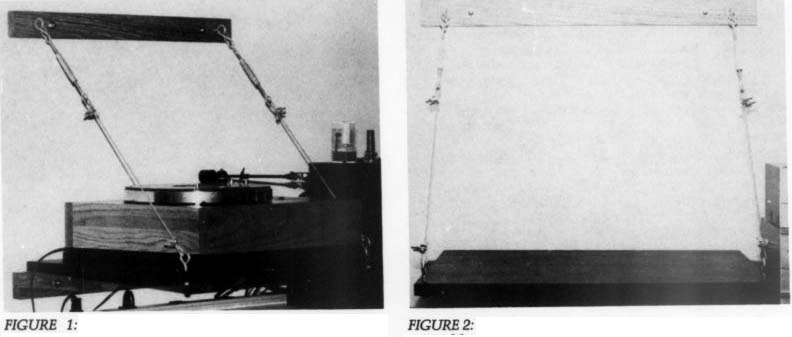
FIGURE 1: Side view of the turntable isolation shelf. (Photograph by Gary Galo, printed by Paul Steinberg.)
FIGURE 2: Front view of the shelf. (Photograph by Gary Galo, printed by Paul Steinberg.)
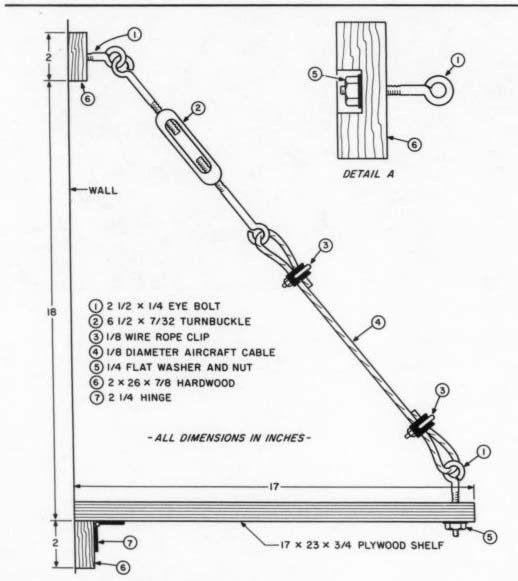
FIGURE 3: Construction details for the turntable shelf. You should use a quality grade of plywood and should be able to find all the other materials at your local hardware store.
... to make sure the shelf is well constructed and securely fastened to the wall. Neither TAA nor I will accept any responsibility if your turntable winds up in pieces on the floor. I have used my shelf for two years, with a very heavy turntable, and have had no difficulties.
An alternate method of fastening the hardwood pieces is to go completely through the wall with long bolts or 3/8 “ threaded rods, which in turn go through two similar hardwood pieces, securely fastened with nuts and Thread Lock, on the other side of the wall. Whichever method you use, be sure that the hard wood pieces are level.
Fasten the turnbuckles to the eye bolts by first opening up each “eye ” enough to slip the turnbuckle on and then closing the eye with pliers. An easier alternative is to use “S ” hooks, which should be crimped closed with pliers.
Unscrew the turnbuckles so that 0.25 ” of thread remains in either end. Connect the other ends of the turnbuckles to the shelf eye bolts with aircraft cable (1/8 ” ).
Adjust the cable length to raise the shelf to a level position. Use 1/8 ” wire rope clips to secure the cable. The weight of your turntable will stretch the cable to some degree. Adjust the turnbuckles to achieve final leveling. You can alter the size of the shelf to suit your turntable.
If your dust cover is hinged, be sure the 17 ” depth of the shelf will be sufficient when the dust cover is open.
Properly constructed, the wall shelf
Should cure the most severe floor vibration problems. I can jump up and down on my floor without affecting playback.
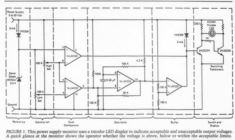
Fig 1
You should also notice an improvement in your system's sound as a result of the excellent isolation between your turn table and floor-mounted loudspeakers, particularly if you are using a direct drive turntable (which probably has poor isolation at audio frequencies). I strongly recommend that you do not hang book shelf-size loudspeakers on your wall, particularly the same wall used for the turntable shelf.
GARY GALO; Potsdam, NY 13676
SIMPLIFYING CALCULATIONS
IN 1922, WHILE studying for a correspondence course, I found it difficult to memorize electrical calculations. I needed a guaranteed method because mistakes are not allowed when searching for answers.
So, I reasoned this way: In those days, all automobiles had 6V batteries. I made those 6V batteries my voltage anchor. I placed an imaginary 1A in each head light, so the two headlights drew a total of 2A from the 6V battery. 6V and 2A-that was all I needed to know and memorize. With these two figures for reference, I learned to calculate, in a simple way, the answers to any electrical combination: ohms, watts, amperes, and volts. When you know any two values, you can determine the other values very simply.
This simplified calculation method can also help you understand resistances in parallel. Simplifying is the key to better understanding.
Of course, some professionals may laugh at these simple ideas. But what professional has never used the rubber eraser on his or her pencil?
L. RusCH; Glenham, NY 12527
A QUICK VISUAL POWER SUPPLY MONITOR
Power supply voltages can be quickly monitored by a circuit equipped with a light-emitting-diode (LED) display. An operator looking at the display can quickly spot whether power output voltage is above, below or within the acceptable limits.
The circuit as shown in Fig. 1 can monitor power supply voltages between 5 and 15V. It has two potentiometers:
one to set the upper voltage limit, the other, the lower voltage limit. When the monitored voltage is above the set maximum, the LED display turns red. Yellow turns on for voltages below the set minimum, and green turns on for volt ages between the high and the low settings.
The circuit does not need a separate power supply. It is powered by the voltage it monitors.
Through simple modifications, the circuit can be adapted to monitor volt age differences between two power sup plies. Should the monitored voltages differ by more than a set value, a visual or an audible alarm would warn the opera tor about the difference. The circuit can also be modified for remote monitoring and the use of a separate power supply.
This work was done by Lloyd W. Taylor of the John Hopkins University, for Marshall Space Flight Center. Reprinted with permission from NASA Tech Briefs Winter 1985.
Submitted by: WiLLIAM H. CAPELLE, JR. Memphis, TN 38112
BOOK REVIEWS
BUILDING SCIENTIFIC APPARATUS
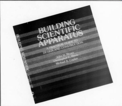
Reviewed by Bill Ruck Moore, John H., Christopher C. Davis, and Michael A. Coplan, Building Scientific Apparatus: A Practical Guide to De sign and Construction, Addison-Wesley Publishing Co., Reading, MA, 1983 (ISBN 0-201-05532-5); $61.95 DON'T LET THE title stand between you and a valuable addition to your library.
This book is loaded with information about designing and building any sort of high technology equipment.
Authors Moore, Davis and Coplan have solid backgrounds in the physical sciences. While this book, in their words, “is a practical guide for the scientist, technician and student who builds scientific apparatus, ” it contains enough information to be a valuable addition to this audio amateur's library.
Each chapter includes a list of references for each topic, as well as a list of manufacturers and suppliers. The first chapter, “Mechanical Design, ” includes information about tools and shop processes, materials (plenty of details here), joining materials (hydrogen brazing, anyone?), mechanical drawing, and a thorough review of mechanics.
The second chapter, 'Working With Glass,’ is probably not very practical for most TAA readers, and 'Vacuum Technology’ is definitely a bit too arcane for most of us, although if you want to build your own vacuum tubes, you'll find enough information here to get started.
The next two chapters are for those on the audiophile “lunatic fringe. ” “Optics ” will help you make your own laser, while the fifth chapter is called “Charged-Particle Optics ” (ever need a dynamic mass spectrometer?).
Most TAA readers will love the last chapter, simply titled “Electronics.” Representing nearly a third of the book, “Electronics ” starts with a simple yet thorough discussion of circuit design, followed by a thorough look at passive and active components. The “Amplifiers and Pulse Electronics ” section features good design basics but is definitely slanted toward scientific applications.
The last part of this chapter, “Hard ware and Construction, ” packs a bundle of information into 15 pages. While it doesn't cover everything in exhaustive detail, the information is practical and correct. Other chapter topics include supplies, digital electronics, data acquisition, extraction of signal from noise, and grounds and grounding.
Until someone writes a hand book especially for amateurs, we will have to borrow from other electronic fields. I have, over the years, built up a fairly comprehensive library which features important information scattered throughout many volumes.
In my opinion, the usefulness of this book rates alongside my favorite, The Radio Amateur's Handbook.
Classic Ckts
A VINTAGE INVERTER NOTE THE similarity of this vintage version of the split load phase inverter to those employed in many 1960s hi fi amplifiers.
The split-load inverter is older than 1942, but other than in amplifiers built by audio amateurs in the 1930s, I can't recall where I first saw it used.
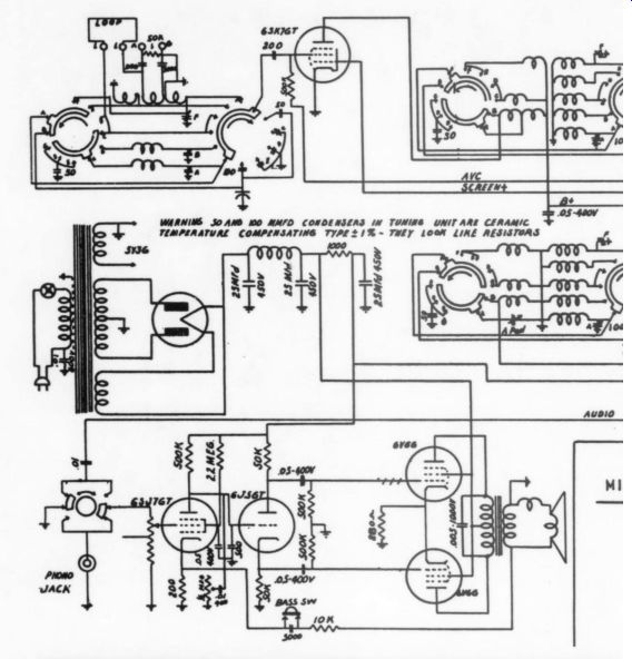
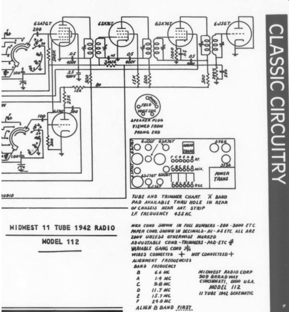
One amateur-built unit was suggested by Clyde Hicks, an old-time radio repairman whose career went back to crystal set days. It used to parallel type 76, in sp parallel 2A3H, Class A put transformers in para output tube DC balanc
I liked the 2A3H in th and if I could find fous Clyde's amp and try it
DON BURGESS San Diego, CA 92117
used the 6C6, capacitance-coupled in in split load. The finals were push-pull ss A. Hicks' design featured two out-
| parallel, and sides reversed to simplify alancing.
in those primitive days. I still own one,
| four more good units, I might build ry it out.
-------------
TUBE AND TRIMMER CHART. A BAND PAD AVAILABLE THRU HOLE IN REAR OF CHASSIS NEAR ANT. STRIP LE TREGUENCY 43S KC MEA COND SHOWN IN FULL NUNBERS -200 -3000 £TC PAPER COND. SHOWN IN DECIMALS - 01 - 85 ETC. ALL ARE 2000 UNLESS OTWERWISE MARKED ADJUSTABLE COND. -TRINMERS - PAD -ETC FF VIRIABLE GANG Cavo 7; WIRES COMMCTED = NOT CONNECTEED + ALIGNMENT FREQUENCIES BAND FREQUENCY
] 66M MIOWEST RADIO CORP A 1.4 MC $09 BROAD wAY S pom CINCINNATI, ONIO USA.
0
MODEL 12 poy rd 1 TUBE 1942 SCHEMATIC F 29.0 McC ALIGN B BAND FIRST.
SHOWCASE
MOSFET MOBILE AMP by Randolph Vikan.
MY LATEST PROJECT WAS a highly efficient car amplifier, made of the best possible components. I was challenged to design an amplifier that would over come the automobile's space and power limitations, so my goal was to come up with something compact but powerful.
My greatest challenge, however, was fitting everything into a 2x3 x6 Kk box (Photo 1). I chose an all-MOSFET design for both the audio amp and the switching power supply. MOSFET's low drive requirements allowed me to greatly simplify the circuitry, which meant conserving space and increasing efficiency. I surface mounted many of the components (Photos 3 and 4), which also helped conserve precious internal volume.
Eight IRFZ20 MOSFETs and an Unitrode 3528 PWM (pulse width modulator) IC formed the base of a push pull 25kHz switching power supply.
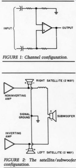
FIGURE 1: Channel configuration.
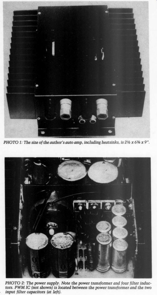
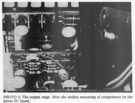
PHOTO 3: The output stage. Note the surface mounting of components on the driver PC board.
I wound the power transformer (Photo 2, mounted to internal shield) on a Ferroxcube 3622 pot core ferrite of 3B7 material. The secondaries of +40V DC and + 50V DC were rectified by very fast recovery diodes (MUR1520 and 1N4937), and filtered by LC networks on each of the four rails.
PWM supplies were voltage-regulated by the 3525, a TL431 shunt regulator and an MCT275 optocoupler, which al lowed me to totally separate power ground from signal ground within the amp. I used all low ESR high frequency supply capacitors, such as Sprague 672D (Photos 2 and 3).
I connected four output MOSFETs (two each IRF9530 and IRF530) per channel to the *40V rails (Photo 3), and connected the driver stages to the +50V supplies. The tiered power supplies in creased the output stage efficiency, allowing it to swing from rail to rail with minimal losses.
I placed a symmetrical dual differential input stage in the driver stages, using 2N2920 and 2N3811 transistors with LM336-2.5 in their current sources (Photo 3). Next, I gain-matched all the transistors in the driver stage to reduce distortion. The resistors I used in the audio stages are all 1% metal film types, while the coupling capacitors were Mylar film rather than electrolytic types (Photo 4).
Each channel was configured as a differential amplifier to improve immunity to external car noise (Fig. 1). By simply switching two wires, I inverted one amplifier channel so that it ran in a bridged mode. This allowed me to use a satellite/subwoofer configuration (Fig. 2). The satellites ran full range while the subwoofer dealt only with mono information below 100Hz (where most of the bass end lies).
In the event of an offset, overheating, excessive current drawn from the +40V rails, or if the battery voltage dropped below 8V, the protection circuitry shut down the amp.
The output power exceeded 120W per channel into 4 ohm loads, with less than 0.02% THD. Meanwhile, the current drawn from the 13.8V source exceeded 40A at this output level.
I had achieved my goals, and best of all, the amp sounds great in my car, giving the impression of almost infinite power reserves.
[If readers are sufficiently interested, Mr. Vikan might be persuaded to do a full-length construction article on his auto amplifier. -Ed.]
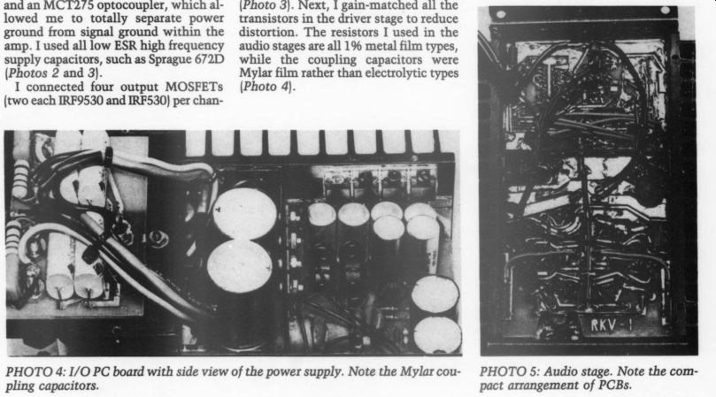
PHOTO 4; PHOTO 5: Audio stage. Note the com pact arrangement of PCBs.
LETTERS
ONE GOOD MOD DESERVES ANOTHER
I WAS GREATLY interested in Hampton Childress' article in TAA 3/86, “Modifying Yamaha's CD2 Player. ” I own a Yamaha CD-X1 and am interested in ways to get more out of my equipment instead of continually running out to buy the latest and (supposedly) greatest new product.
I'm glad to see someone has modified a Yamaha rather than the ubiquitous de facto standard Philips/Magnavox. I was beginning to think only Philips made a modifiable player.
I've not been dissatisfied with the out of-the-box Yamaha and have enjoyed every CD in my small but growing collection. With all the anti-CD vitriol in some underground audio publications, however, I began to think I was in the minority (nay, outcast!). To counter this, I planned to purchase a Transcendence CD player (a modified Magnavox 2041) from Frank van Alstine. I was about ready to compare it to my CD-X1, and then Mr. Childress' article appeared.
Thank heavens! My budget just wasn't up to a new CD player, and I knew I'd have the best of both worlds if I could easily and (most importantly) inexpensively modify my CD-X1. Are the CD2's modifications directly transferable to the CD-X1? While I enjoy reading TAA, I'm a closet amateur at best and am “uncomfortable with this kind of work, ” especially about actually going inside and ripping the guts out of this not-so inexpensive player and then trying to put it back together again. I have assembled a Hafler preamp (DH-110) and two DH-220s from kits, but not without a great deal of attendant nervousness. On a scale of a Heath kit to a Hafler, how difficult are the suggested modifications? I have some electronikker friends at work, and I've discussed these modifications with one of them. If I decide to modify my CD player, I will probably have him do the work. I don't want him to put this project on his schedule, however, until I have some idea of how transferable Mr. Childress' ideas are to my unit.
By the way, Yamaha's address wasn't given in the article, and I'd appreciate it so I could write for the CD-X1 technical manual.
I still plan to visit the Frank van Alstine rep. and compare the standard CD X1 with the Transcendence player, and if I do the modification, I may even visit him again for another comparison. I'll be interested to hear the difference.
PHIL RAYMONDO; Lake Park, FL 33403
Mr. Childress replies:
Since the release of the 3/86 issue, I have been pleasantly surprised by the response to modifying the allegedly “audiophile non-standard ” Yamaha player. Like you, I no longer think Yamaha owners are odd nuts, just in the minority. When a manufacturer has to compete with other players whose blazing orange stickers advertise “pure, perfect sound, ” it's no wonder they must work hard to be as popular.
The CD-X1 is probably modifiable ac cording to the guidelines set out in my article. I borrowed a friend's CD-X1 and did a somewhat superficial parts inventory. The D/A (digital-analog) converter in your unit is the same Burr-Brown device I discussed, and is deglitched by the same analog switch. Therefore, that part of the mod sequence is directly applicable.
The filtering circuits also appear similar, but I don't have the schematic diagram necessary to determine the ex act values and locations of capacitors, resistors, and IC (integrated circuit) op amps (and their respective improved replacements). This also applies to the power supply, except the CD-X1 relies upon traces on the circuit board to route current to various active devices as op posed to the wires seen on the CD2. My life would have been simpler had supply wiring been done this way in my player.
Both players are similarly coupled at the output through an electrolytic capacitor. Should you decide to replace the cap with an upgrade, all should be well.
If you go the route of servo-controlled DC offset circuitry (which I most heartily recommend), you should analyze the last stage amplifier circuit.
Refer to my article in the 3/86 issue and note this servo design is based on a couple of key parameters. First, you can effectively control the offset of your replacement choice op amp for IC303 304. To ensure this, verify similarity of resistor values within your player corresponding to R315/317 and R316/318 in the CD2. The servo will probably work if they are close, but otherwise may require some tweaking. Make sure the specified offset for your replacement op amp is not wildly greater than that of the LM318 or Burr-Brown 3507]. If you utilize the servo circuit, be sure to test offset at the output with a reliable voltmeter before you operate the modified player in your system. Mute circuitry will be in effect if you are not playing a disk, so measure DC offset at the point corresponding to the junction of IC303 and R319 (IC304 and R320 for the other channel).
Also, measure the voltage across the 150k resistor attached to the output of the servo (IC1). It should be less than 7 or 8V to give the servo op amp some headroom. Remember to jumper the existing output capacitor as shown in Fig. 1 of the article.
On a scale of Heath to Hafler, it's time for the bad news. The knowledge required to safely effect improvements pushes the difficulty rating off the scale.
I wish not to scare you away, but rather to warn you to be careful with circuits as complex and potentially destructive as these (especially the power supply).
Do enlist the help of someone who understands the circuitry.
Red-faced, I apologize for inadvertently omitting Yamaha's address. You can order the schematic diagram from: Yamaha Electronics Corp., 6660 Orangethorpe Ave., Buena Park, CA 90620.
As a TAA reader, I would be interested in your impressions of the van Alstine player versus the modified (or unmodified) CD-X1. I wish you the best of luck and enjoyable listening.
AUDIOPHILE NEEDS DIRECTION
I HAVE BEEN trying to track down the schematic and/or service manual for the Accuphase E-202 integrated amplifier.
I've already written to TEAC Corp. (a past US distributor), but they did not have the schematics because this particular product has been discontinue If any reader can help, please write to me, in care of TAA.
STEVEN BECUTI; Canton, MA 02021
WHAT'S A POOGE!?
I HAVE A couple of questions concerning Walt Jung's POOGE articles. Though I have successfully built a number of TAA and other projects, my design capability is limited and so I value the experience of others.
I have a set of Magneplanar MG-IIAs and read where Mr. Jung substituted parts in his system's crossover network.
So I can avoid tearing my speaker open twice, can he tell me what changes he made? I built a Leach wideband preamp several years ago which I intend to upgrade.
Is it worth it to rebuild the unit, or should I build something different? For example, I occasionally hear of an FET (field effect transistor) version, and I'd appreciate any information about the conversion.
Finally, and perhaps the silliest, concerns the POOGE concept itself.
Though this term has permeated the TAA jargon, I am unable to find a single definition. I know who POOGE-1 and POOGE-2 are, but just what does POOGE stand for?
RICK LEVIN Dedham, MA 02026
Contributing Editor Jung replies:
First, in the interest of better sound, here's what you can do to the Magnepan speakers. (This is a fascinating story. It started for me many years ago when the system (later pinpointed as the Maggies) started to sound rough and harsh. The fix turned out to be cleaning up the signal into the Magnepans.) First, improve the connections into the speaker. My speakers came with a pair or rather weak contacting banana jacks which simply would not securely grip a plug, particularly on a substantial cable. I tried the heavy-duty, gold-plated brass binding posts, which helped greatly. To make a long story short, I finally soldered the cables directly into the speaker at that end (this may not apply for all, but it does eliminate the contact variance if your speakers stay put).
Since my amp was fused, I also by passed the tweeter fuse. If you can't, try a soldered-in fuse type (such as the pig tail units available from Digi-key).
Without doing anything else to the speakers, these two steps improved the sound in mine quite a bit. I don't know about your speakers' connections, but attention to quality at these high current contacts is critical to good sound, initially and over time.
Within the speaker wiring, I changed the crossover caps by substituting with improved motor-start type polypropylene units. My crossover values are 10, 17, and 30uF. The originals were flat style Elpac polyester, and I replaced them with Sprague 325Ps. Each of the new caps is shunted by a smaller .22uF polypropylene. You will find it next to impossible to fit the new caps into the speaker's slim base. You can however, bring out the wiring from the woofer/ tweeter and coils, and place the big caps in a box screwed down to the base plate, behind the speaker's panel.
As an alternative, bi-amp the woofer and tweeter using separate high quality wiring. Back them to two good amps driven from a low-level crossover. I have not tried this yet, but I suspect it could give good results. Experiment with speaker placement in your listening room, both relative to one another and from the back wall. You may like a slight toe-in. My Maggies are about 4' away from the wall, and focus on the 'sweet spot' listening position, about 12' away. Sound deadening or absorbent material on this wall helps the overall imaging and improves the sense of depth.
I hasten to note that any or all of these suggestions will most likely void your speakers' warranty. Carefully consider this possibility before making any modifications. The people at Magnepan may take a dim view of all this, regardless of how positive I am about the sound improvements. On the other hand, since these changes are relatively simple, I wonder why they are not standard factory issue? For midrange clarity, overall balance, and lateral and front/back imaging precision, these speakers take back seats to very few systems. Most people who have heard my speakers say they sound better than any Maggies they've heard before.
On the meaning of POOGE, it's funny how this seems to trouble some while others just find it interesting or amusing. Yes, it is both a verb and a noun, and has been rumored to be an individual and even an organization. We have a local audio hobby group which exchanges POOGE ideas, such as seen in TAA 3/86. You can execute a POOGE, and you can be a POOGE (obviously, a POOGE is one who POOGES!).
I find audio POOGEing great fun, and all who wonder about the word's derivation should note the closing lines of “POOGE-2 ” (TAA 4/81). After all, fun is what this hobby is all about.
As for the Leach preamp, in FET form, I don't know for sure. Try writing to Rod Rees, in care of TAA. I seem to recall Rod used an FET preamp based on the Leach.
Have a good and lasting POOGE, and happy listening.
A FISHY PHOTO looked fishy, but I wasn't sure until I started compiling a parts list to rebuild a friend's Dynaco tuner according to Ben Poehland's article.
Then, I realized the partial schematic on your cover to illustrate the title ''FM 3 Rework'' was not a Dyna FM-3 at all. It was an FM-1. Who are you trying to fool, anyway? Do I win a free subscription renewal for being the first to discover ''what's wrong with this picture? ”
DAVID BARNETT; Little Rock, AR 72205
Rats! We thought we could get away with it but were caught by your sharp eyes. Our files had the FM-1 which we converted later with the add-on kit for Stereo Multiplex. In any case, now you know that covers are just art, not information.
-Ed.
IMPROVING UPON AN EXCELLENT DESIGN
I AM BUILDING the Borbely Preamp (TAA 4/85, 1/86), and would like Mr. Borbely's advice concerning two changes I plan to make in his excellent design.
With all the discussion in TAA about the importance of low-impedance power supplies, I find Mr. Borbely's power distribution suggestion appalling. Only the RIAA-2 board is supplied directly from a regulator. Both the RIAA-1 and line amp boards receive their ''regulated'' power through 100 ohm resistors, while the tape buffer receives power through two 100 ohm resistors in series.
Instead, I plan to use one pair of Sulzer regulators (TAA 2/80, 1/83) per channel (one positive, one negative), and run all boards at the same voltage directly from the regulators. I was planning to run the regulators at 24V, but a friend suggested I use the 100 ohm resistors to drop the supply voltage since 24V may exceed the voltage rating of some transistors.
Would Mr. Borbely please comment on this? Can he recommend a single voltage which I can safely use for all boards without significantly changing the boards' overload capabilities or bias cur rents? Or, could he recommend possible changes to the bias circuit? I also plan to modify the phono stages so I can use moving coil (MC) cartridges.
I can think of three things I must take into consideration when making these changes: input impedance, noise and gain. Although some people recommend using a high impedance load, MC cartridges are generally loaded with 100 ohm or less. I assume just changing the 47 k-ohm input resistor on the RIAA-1 board will accomplish this, but I wonder if this will affect the first stage biasing? As far as noise is concerned, either the phono section is quiet enough to use with the low output levels of MC cartridges, or it isn't. Mr. Borbely seems to have taken great care to minimize the noise, so I suspect the preamp will work fine with MC cartridges.
Finally, I come to the issue of gain. Approximately 20dB extra gain is required to accommodate a typical MC cartridge. Since the preamp uses a two stage phono section, sufficient gain should be available. The question is, how do you divide that extra gain be tween the two stages? I must be very careful when increasing the gain of the first stage. It is linear and must amplify the unequalized RIAA signal, which has a strongly-rising high end. The stage's open loop gain has a strongly-falling high end (typical of all op amps), so I must be careful to assure enough gain margin is at the high end.
Could Mr. Borbely recommend a way to increase the phono gain by 20dB and include suggested resistor changes? In closing, I want to congratulate TAA on its consistently excellent and continually increasing quality. It still amazes me how well this small “underground ” magazine manages to keep abreast of current audio trends, and sometimes even takes the lead, as in Walt Jung's excellent investigation of slew rate limiting.
GLENN MANUEL; Richardson, TX 75080
Mr. Borbely replies:
As I pointed out in the preamp article, feel free to adopt any power supply arrangement you like. Although not mentioned in the article, I have used several different supplies in my models. One uses a dual regulator approach, based on a Sulzer design from TAA. This supply was developed for my MC-preamp. You might consider this design for your preamp as well.
Yes, there is a reason for the 100 ohm drop resistors. As far as the RIAA-1 is concerned, it is, as you correctly suggest, to avoid too high a voltage across the ROHM transistors. As for the tape buffer, it is a question of power dissipation in the MPSA transistors. If you would like to run all boards from the same voltage, I suggest you use + 22V. This will not significantly affect the overload margin, and doesn't require any biasing changes.
Concerning MCs, you can't use the RIAA-1 board without modifications. Although it is a low-noise amp in its own right, it is not optimized for MCs. Consequently, I designed a modified version of the RIAA-1 stage with 20dB extra gain (TAA 4/86, 1/87).
TONE CONTROLS FOR BORBELY'S PREAMP
FIRST, I MUST say TAA is my favorite magazine, and I especially enjoy articles dealing with circuit design. I am impressed with the Borbely pre amp and plan to build one, but since my audio system is part of my video setup, I want to include tone controls. I plan to use the line amp as an op amp and insert the tone controls in the negative feedback line. I anticipate a +12dB range, with a low breakover point of 200Hz and an upper breakover of 4kHz.
Can Mr. Borbely recommend a filter circuit other than the old “Baxandall? ” I also want to add a headphone amp.
I think the line amp with the MOSFET outputs will work if I parallel two MOSFETs for Q12 and Q15. Any comments? Finally, I'd like to add an absolute phase switch, but I cannot come up with a method simpler than an inverting stage with a switchable by-pass. Is there a better solution?
STEVE PLATT; Lancaster, CA 93534
Mr. Borbely replies:
I am afraid I can't answer your questions at the moment. Though it is possible to convert the line amp into a tone control stage, I wouldn't recommend a “Baxandall ” circuit. Not only is it an inverting circuit, it is also asymmetrical and the inflection points are difficult to control.
I suggest a non-inverting circuit with symmetrical boost/cut characteristics, but it will take time to design it. If there is sufficient interest for such a circuit, let the Editor know and I will put it on my list of projects.
The headphone amp is also a possibility and would probably work either by paralleling two TO-220 FETs (field effect transistors) or by using one high current FET. Again, I don't have a circuit ready.
Several readers have asked about the possibility of phase selection. I am working on such a circuit, so again, let the Editor know if you wish to see it published in TAA.

----
Also see: