A 500W MOSFET POWER AMPLIFIER, PART II
PART ONE OF this do-it-yourself project, I began to describe the power module. In this section, I'll ex plain why softstart switching is necessary, and describe the circuit and its construction.
Installing the power module is only the first step on the way to a complete 500W amplifier. Most of the work still lies ahead, including stuffing the PC (printed circuit) board, constructing the power supply and box, and wiring. To guarantee you end up with a professional-sounding amplifier, you must be an experienced solderer and a skilled technician. It is hard work, and cannot be done in one weekend.
Softstart
Stage experts know switching on a bank of output amplifiers is nearly impossible. You need two people for this operation: one at the automatic fuse, and the other switching on the power amps, one after another. When the last power block is switched on, the automatic fuse will blow, which means you must switch off every out put stage, switch on the automatic fuse, and begin the same procedure again. This never-ending story is not just my wild idea, but rather it is based on everyday experience.
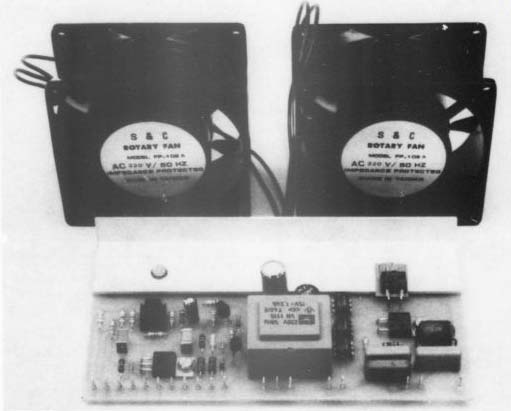
PHOTO 1: Control PC board and fans.
The culprits are the high-starting current peaks of the power supplies, which will overload many household electrical installations with quick fuses or circuit breakers. The solution is to limit the start up current pulse to tolerable figures. In addition, the automatic circuit guarantees the amplifier will reset with a softstart after a power supply voltage loss. By the way, this problem is often not ad dressed even in high-quality products.
I will not discuss the remaining checklist items in detail now, but I will later when I give the circuit description.
Circuit Power Module
At first glance, the circuit does not reveal any unusual features, although the circuit's simplicity is somewhat surprising.
Actually, this concept resulted from numerous failed efforts to apply new methods. I ended up with a circuit which is nearly identical with a Hitachi application. My description, therefore, will be restricted to a few special details which enhance the final construction.
Electronic symmetrization takes place through the two input operational amplifiers and the output stage, the latter operating as a true differential amplifier. In concept, it corresponds to an instrumentation amplifier, as used in testing equipment. In the event of overload, R1 and R2 are used to perform input cur rent limitation. In connection with C10, they form an RF-filter. The sub sonic filter consists of R3, R4, C1, C2, and R8, R9, C5, C6. I used a 4558-type opamp with low noise, which overcomes high-input bias and supplies a clean slew rate limitation.
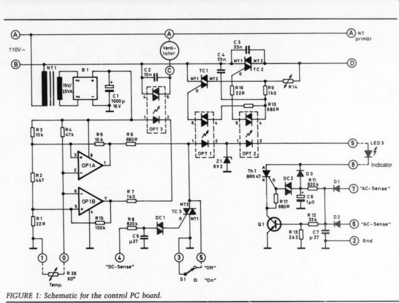
FIGURE 1: Schematic for the control PC board.
For these reasons, I definitely prefer the 4558 over the T1072 or NE5532 types.
The opamp's power is supplied through the NTC (negative tempera ture coefficient) resistor directly from the operating voltage rather than from the common drop resistor. The 4558's characteristics are such that it will operate correctly even with small supply voltages. For instance, at the beginning of the power supply-electrolytics' charging phase, directly after switch-on, the op amp is already working in a normal fashion. This effect, along with the amplifier's sym metrical construction, guarantees minimum switching noises even without a delay relay.
The pair of differential amplifiers, Q1/2 (ECG40), is distinguished by low-noise, low-offset voltage and high-current gain at a maximum 100V collector-emitter voltage.
----------
TABLE 1 ---- PARTS LIST FOR CONTROL PC BOARD
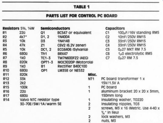
Resistors 5%, VaW R1 220 R2 ak7* R3 10k R4 47k RS 10K R6 6800 R7 1k0 R8 820k RY 1k0 R10 6800 R11 820k R12 33k R13 2k2 R15 100k R16 220 R17 6800 R14 Semiconductors Q1 BC547 or equivalent D1, 2 1N4004 D3 1N4148 21 C6V2 (6.2V zener) DC1,2 ECG6406 (Sylvania) Th1 BRX47 TC1-3 TW7N600FZ2 (AEG) OPT1-3 MOC3020P (Motorola) B1 Rectifier B40C100 oP1 LM358 or NE532 NT1 Valvo NTC resistor type 30-70E/5W/1A/warm 5E Capacitors C1 100 uF/16V standing RM5 C2 10nF/250V RM15 C3 33nF/250V RM15 ca 33nF/250V RM15 C5 0u27 MKT RM 7.5 C6 1x0 electrolytic RM5 Cc? O27 RM 7.5 PC board transformer 1 x 15V/1.5V A PC board aluminum bracket 20 x 20 x 3mm, 150mm long insulating washer, T0220 insulating nipples, TO3 screws, M3 x 16 (Metric. Use 4-40 x 5 ” in lieu) lock washers, M3 nuts, M3
*Note: European designations for parts values use the following conventions: 4k7 = 4.7k
[thereby avoiding the risk of the elusive decimal point being lost]. Under capacitors, 0427 =
0.27uF, and 140 = 1.0 uF.
-----------------
---
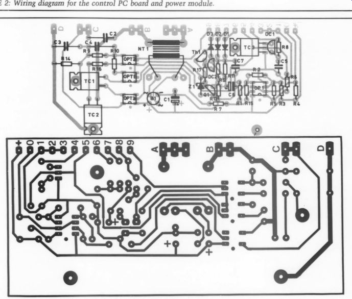
Figs 2; 4 (PCB and stuffing guide).
So as not to exceed the allowed collector-emitter voltage of the pair of differential amplifiers, Q3 and Q5 will reduce the collector voltage to approximately +42V.
Limitation of the emitter voltage to +42V is provided by the division of the input voltage in a 2:1 ratio via R21, R10, D1, and D2. At the same time, this avoids 'latch up, ” which could occur if the base voltage at Q1/2 exceeds the collector voltage.
Q3, Q5 and the entire driver circuit would then lose the current, and the output would drift against the supply voltage.
In the driver circuit (Q4-Q8) positive half, the differential amplifier (Q4, Q6) is high-gain as well as fast switching. This segment has 3.5mA idle current, with the peak current limited to 10mA.
The negative half of the driver is the current mirror formed by Q8, which also supplies 10mA and doubles the open-loop gain. D6 produces the bias voltage for the quiescent current, so a trimmer is not necessary. Z4, Z5 in connection with D4, D5 limit the maximum gate voltage of the transistors and, there fore, limit the output current to approximately + 35A.
C8-C11 improve stability against RF oscillation. Because of properly selected gate resistors, the switching difference of the N- and P-channel MOSFETs is symmetrical. NTC resistor R38 on the printed circuit board serves to control the heatsink temperature and is connected electrically to the control PC board. The ground wire on the PC board is “lo noise-gnd, ” and is connected with the center of the supply voltage via L1, R36.
Construction
Construction of the power module should not cause you many problems. When stuffing, it is best to start with the resistors, followed by the soldering pins, transistors, capacitors and NTC-resistor. Mount the heat sink last. To guarantee adequate insulation and correct positioning, place insulating nipples into all TC3 holes. Cover the hole for the thermal sensor with silicone grease.
Place the PC board on the heatsink and begin with the insulated mounting of the transistors (see TAA 4/86, Fig. 2). After you have tightened all screws, solder the transistors and gate resistors. When you have soldered all remaining components on the soldering side (D4, D5, D7, D8, Z4, Z5), your power module will be complete.
Take time to check the power module before you install it. First, use an ohmmeter to check the insulation between the heatsink and the transistor packages. With 48 holes, it is possible that a leftover drilling chip could cause a short-circuit.
For your first test, begin on a small portion and supply the module with current limitation by using a double power supply. A +8V supply voltage is sufficient for this test. If the out put voltage is only a few mV and out put signal is all right when a small sine wave input is applied, the module is probably OK.
Now, all you need is a big power supply and your amplifier will be complete. But this is not a quick process. Cost-saving versions need protection circuits, and the amplifier will only be ready when it is connected with the control PC board.
Control PC Board
With the exception of short-circuit protection (already discussed in Part I), all safety circuits are on the control PC board, including automatic soft-start, loudspeaker protection (DC protect), and heatsink temperature control.
The electronic control can be di vided into the 220V circuit and the low-voltage current control portion.
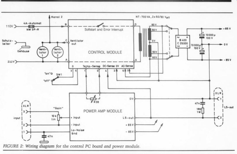
An overview of the functional connection is shown in the wiring diagram (Fig. 2). It has its own non switched power supply to enable electronic control functions, even with a switched-off output stage (e.g., extremely high temperature).
Before I discuss the circuit's de tails, I want to describe its function.
In the 220V circuit, the power sup plies and blowers must be switched together. The control switches are triacs which, when compared with relays, are smaller, cheaper and corrosion-free. Furthermore, they do not produce cut-off flashes or, therefore, interference pulses.
Here are typical characteristics of triacs:
1. As electronic switches, in contrast to thyristors, they can also switch AC-current.
2. The control electrode is called gate, the common electrode is MT1, and the output is MT2.
3. To switch on the triac, a current pulse must be directed to the control gate. The trigger pulse can be either positive or negative; the polarity can even be opposite the load current's direction. Operation range includes all four quadrants of the family of characteristics.
4. Once switched on, the load current flows permanently. The triac switches itself off only if it decreases to a value below the so-called holding current. A switch-off via the control gate is not possible.
5. If you use a DC current instead of pulses, load currents below the holding current can also be switched.
6. In the 'on' state, the voltage drop via MT1 and MT2 is 1-2V, and changes little throughout a large load current range.
7. Triacs can also switch on automatically should the load voltage rise speed exceed a critical value (slew rate in V/sec). This occurs especially when the 60Hz AC voltage is switched in the peak of a half-wave.
Toroidal transformers represent a nearly ideal inductive load and can not, therefore, be controlled with pulse-driven dimmer circuits or with the common zero-voltage circuit breakers. When phase shifting be tween current and voltage leads to a dip below the holding current in the middle of the phase, the triac falls out, and a more or less uncontrolled phase intersection results.
This presents the following problem: already the smallest asymmetry between the positive and negative half-wave (caused by a slightly different phase lead angle), the dip quickly leads to a considerable in crease in direct-current components due to the low winding resistance.
Therefore, it should not be surprising if the fuses blow when a transformer is operated through a dimmer.
To avoid this problem, use a suitable parallel-switched RC part for phase compensation. A better method is to replace the pulse trigger with a direct-current control (see point 5), which will allow the triac to switch when the holding current falls. You can also get good results from special coupling circuits. For some time, optocouplers have featured a diac out put instead of a photo transistor. This light-reactive diac works as a switch, whereby the biasing potential of 400V makes it possible for direct switch-on between MT2 and the gate. As a result, the control current can be taken out of the load-current circuit, which means a separate current supply for this control circuit will not be necessary.
Some standard types of triacs, such as TIC236, are not suitable. First of all, the critical voltage parts are not strong enough to prevent a parasitic self-ignition when a current peak occurs. This effect can make the soft start inactive. Switching on softstart in the voltage peak following a power failure can also switch on the main triac and cause a full in-rush current.
Further weak points include the relatively low sensitivity and the high-holding current. In addition, asymmetry in the output circuit is possible. Measurements on TIC236 have shown a voltage drop of 1V in the positive and 3V in the negative half-wave. This difference seems transformer.
In contrast, consistently good results have come from the AEG-type TW7NG600FZ2. The remaining volt age in this gate-sensitive triac is sym metrical (+ 1V), while other advantages include I; = 10mA, Lnax = 7A, and a TO220 package with larger wiring traces.
Switching With Softstart
The starting procedure can be divided into two automatic steps. First, to effectively limit the starting current, switch the power transformer via a serial resistor (softstart). Only when the filter electrolytics have reached their full operation voltage (full power) will the resistor be bypassed.
This functions as follows: it is assumed there is no signal at the input DC-sense (direct current protection).
As long as switch S1 is in the 'off' position, the control current flowing through R6 will be led away to ground. LED1 and LED2 remain without current, TC1 and TC2 receive no control and interrupt the primary current circuit of the toroidal core transformer. The output stage switches off. When starting (S1 at “on ”), the short-circuit will be compensated for and the control current will flow via LED and Z1. With OPT1, R9 and R10, starting triac TC1 will be fused and the power trans former that lies in series via the hot conductor R14 will switch on smoothly.
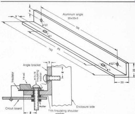
--------FIGURE 3: Diagram for connecting triac TC2 to the heatsink
and PC board. Note the 100% insulation between the triac and heatsink
due to the AC voltage in the TC2 package. Dimensions are metric.
In this case, I chose a hot conductor instead of a wire-wound resistor because it is extremely resistant and, due to temperature dependence, is most suitable for the starting current limitation.
When the current first begins, R14 is cold and has a typical resistance between 30-70 ohm. During this moment, the entire supply voltage rests on the NTC resistor. Within a fraction of a second, the resistor heats up so its own resistance decreases to only a few ohms. The starting current peak will be absorbed, but at the end of softstart (before the actual start), the entire supply voltage lies on the transformer so no appreciable current flows in the circuit for the ensuing bridging across R14.
After the filter electrolytics have been charged up to their nearly-full operational voltage, the next step is to bridge the main triac across R14, thereby connecting the transformer directly to the power supply. This bridging is done through OPT2 and LED2. The full-wave rectifier, consisting of D1 and D2, is used to control the supply voltage (AC-sense). As soon as the secondary voltage has been charged up to approximately 70%, Q1 will connect through.
About one second later, the voltage at C6 will reach +20V. Diac DC2 will switch the small thyristor Th1 so that the series connections of Q1, Th1, LED3 and LED2 become conducting.
Since the operating voltage of this series still lies under the zener voltage of Z1, the zener becomes current-less and the control current flows through LED2. At this point, the OPT2 activates and TC2 connects through. As soon as OPT2 switches on, the entire control current flows into the gate of TC2 due to R10. TC1 cuts off and R14 cools.
Power Failure Restart
On occasion, your AC line power may fail. No matter what the cause of the power loss, and no matter how brief the cut out, you should restart with a softstart, as long as your circuit design can quickly switch off the main triac.
A voltage-monitoring system a round Q1 detects power supply failure. Filter capacitor C7 is intentionally narrowed to 0.27uF so that after a short interrupt, the supply voltage will break down to the point where transistor Q1 is blocked and, there fore, thyristor Th1 is put out of operation. Correspondingly, the current through LED2 will be interrupted and the main triac will fail during short time supply interrupts.
At this point, restart is done by the starting triac through the cold switching NTC resistor, in a manner identical to the above-described nor mal switch-on. You can be sure the switching delay for the main triac (circuit part around Th1) will operate correctly when a short-circuit occurs through D3 and operating C6, be cause when power is switched on again, this capacitor will have no load until the Th1 and the main triacs are switched on. Also, C6 must be charged again, from zero to 20V, so that the delay time of one second can be achieved even after short power supply failures. Capacitors C2, C3, Loudspeaker Protection The normal type of loudspeaker protection circuits consist of a low-pass filter and a relay which interrupt the loudspeaker's DC voltage connection. It is unlikely, however, that a circuit of this type can handle the load. I tried using a high-quality relay with a 15A contact, but even during switch-off at 4 ohm load and 40V DC, a permanent electric arc formed, making interruption impossible. Because the speaker ceil resistors are always smaller than the nominal impedance, you can forget using such a loud speaker relay for an output stage with + 85V supply voltage.
The alternate method described here is unusual, simple and effective.
The loudspeaker's signal comes over the DC-sense connection to low-pass filter R8/C5. As soon as the voltage at C5 reaches approximately 20V (the polarity is not important), DC1 will switch on and TC3 will be triggered.
This effect is nothing more than switching S1 to the 'off' position.
The power transformer will switch off and, at the worst, the filter electrolytics will be discharged via the loudspeaker at a relatively harmless averaging discharging time of about 50mSec.
This DC voltage protection has a locking function, which means that after a single trip, the amplifier will remain in the switch-off position and an automatic switch-on will not take place. The reason is simple: once switched on, the TC3 holds its own current. To put it into operation again, S1 must briefly switch off, which allows T3 to short-circuit and cut off. Now you can switch on the amplifier again, if the problem has been corrected.
Temperature Control
The heart of the circuit consists of bridge connection R1-R4 and R34, as well as the dual operational amplifiers OP1a and OP1b. At approximately 60°C, the fans switch on because if the amplifier exceeds its maximum temperature of 95°C, it will switch off. The temperature sensor is a PTC (positive temperature coefficient) resistor, which has thermal contact with the heatsink. Contrary to NTC resistors, PTC resistors have a considerably higher temperature coefficient, thereby making it possible to define the switch points with low temperature hysteresis.
At room temperature, R34 has approximately 80 ohm. At approximately 60°C, 100 ohm will be exceeded (beginning of the transition region), the voltage difference at the inputs of OP1b will change the sign, and the OP output will drop from 15V down to 0V. Current now flows in LED3, so the diac output of OPT3 switches on the fans. Additional power triacs are not necessary since the fans' low-current input make it possible to have a direct switching with the optocoupler output.
As temperature increases, the resistor of the PTC resistor increases quickly. At approximately 95°C, it reaches 22k so that OP1la switches over, LED1 and LED2 become current-less, and the power transformer switches off.
After a suitable cooling period, the power supply automatically switches on again via softstart. Due to the low switching hysteresis, in the range of 1°C, a typical failure time lasts 30 seconds to one minute before restart occurs.
When assembling the control PC board (Fig. 4b), always remember the area around TC1 and TC2 up to the power transformer contains the full AC line voltage. To widen the insulation range, cut off connection #5 from the three optocouplers. Do the same with the center connections, the triacs, and TC1 and TC2. No drilling holes or soldering points are found at the corresponding points of the PC board. Attach two triacs with screws.
TC2 will cool via the heatsink (temperature coupler) from the package side panels. Since the mounting flange of TC2 is at a considerable voltage, you'll find a mica and insulating nipple insulation attachment is indispensible. Naturally, this should not be applied to TC3. This triac is used in a low current circuit and does not need heatsinking. It can be attached by its three electrical connections. To prevent the PC board transformer from becoming loose during use, put a little glue on the middle of the bottom and press it on the PC board when soldering.
Make all wiring connections on the conductor side, namely, corresponding to the circuit diagram from 0-9 (low current side) respectively, from A-D (220V circuit). In addition, you'll find the IC/optocoupler pins are marked by a spot on the conductor side.
By H. J. Heckert
----
Also see:
PREEMINENT PHONO PREAMP, By John H. Roberts
A WIDEBAND POWER SUPPLY, By Jan Didden