A WIDEBAND POWER SUPPLY
SEVERAL ARTICLES HAVE appeared in TAA and elsewhere, stressing the need for clean, stable and wideband power supplies for preamps. Several authors, most notably Mike Sulzer! have provided excellent circuits for such high-quality supplies.
I have used Mike's circuits, as ex tended by Breakall et al? with a pre regulator. I tried providing more out put current by adding an extra pass transistor? but I was disappointed with the results. By carefully selecting a single pass transistor, however, my design can provide several amps with the same specs as, or better than, the original 100mA Sulzer circuit. I designed an etched board to hold the circuitry, which can be used for either a positive or negative out put voltage. A pair of these boards will provide state-of-the-art preamp power.
The Circuitry
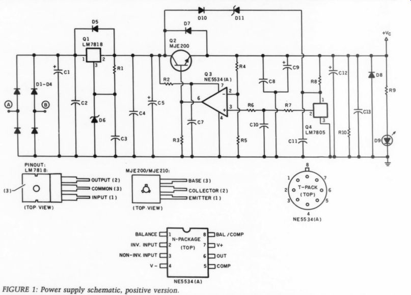
The schematics (Figs. 1 and 2) follow a now-familiar setup. I used a standard three-terminal voltage regulator as a preregulator. It is followed by a feedback series regulator. Note the... [...]
NE5534(A)
FIGURE 1: Power supply schematic, positive version.
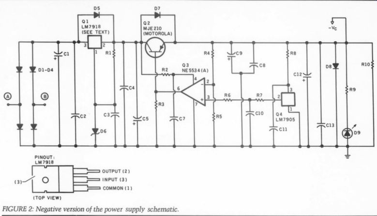
FIGURE 2: Negative version of the power supply schematic.
PINOUT: LM7918
[...] for the negative. Do not substitute.
These particular transistors are essential to the circuit's excellent performance, especially at higher currents-F; of 65MHz, I. maximum of 5A, and a flat, high Hg. up to several amps. Though their V.. maximum is limited to only 25V, they are the best you can find for power supplies, pre amps or headphone amps.
The reference voltage for the regulator is provided by a 5V three terminal regulator with passively filtered 1/0. Because the reference regulator is driven from the final out put, you must facilitate start-up from D10, D11. The negative version, however, will start up on its own.
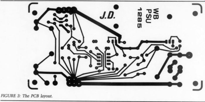
Board Layout You can configure my board for either a positive or a negative voltage version by rearranging jumpers for the connections of the three-terminal regulators and the error amp supplies.
Diode and some capacitor polarities will also differ. Refer to Figs. 4 and 5 for the stuffing guides. The board layout appears in Fig. 3.
I have provided generous heatsink space on the board. For output cur rents up to .8A, the usual finger heat sinks are adequate for Q1 and Q2. If you choose a Q2 heatsink that is a bit larger than the other one, the built in thermal protection of Q1 will protect the entire circuit. For higher cur rents, up to 2.5A, use an angle bracket and mount the assembly on a larger heatsink or enclosure walls. In this case, be sure to isolate Q1 and Q2 with washers and grease. For more than 1A output current, you will need a TO3 version (3A) for Q1, such as the LM350K (+) or the LM345 (-).
------------
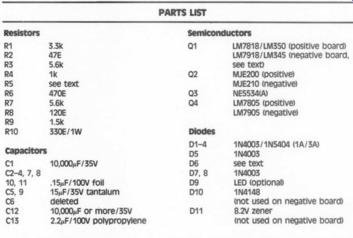
Parts List
sion by rearranging jumpers for the connections of the three-terminal regulators and the error amp supplies.
Diode and some capacitor polarities will also differ. Refer to Figs. 4 and 5 for the stuffing guides. The board layout appears in Fig. 3.
I have provided generous heatsink space on the board. For output cur rents up to .8A, the usual finger heat sinks are adequate for Q1 and Q2. If you choose a Q2 heatsink that is a bit larger than the other one, the built in thermal protection of Q1 will protect the entire circuit. For higher cur rents, up to 2.5A, use an angle bracket and mount the assembly on a larger heatsink or enclosure walls. In this case, be sure to isolate Q1 and Q2 with washers and grease. For more than 1A output current, you will need a TO3 version (3A) for Q1, such as the LM350K (+) or the LM345 (-).
Customizing For optimum results, spend some time deciding on the best configuration for your system. I suggest you use two separate transformers and two positive regulator boards (they perform a bit better than the negative boards), connected as in Fig. 6a. If ...
----------------
Customizing
For optimum results, spend some time deciding on the best configura tion for your system. I suggest you use two separate transformers and two positive regulator boards (they perform a bit better than the negative boards), connected as in Fig. 6a. If ... you use existing equipment with a standard CT (center tapped) trans former, the setup in Fig. 6b will still give you excellent results. You can also use two CT transformers in the Fig. 6a setup, connected as in Fig. 6b.
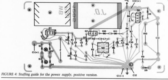
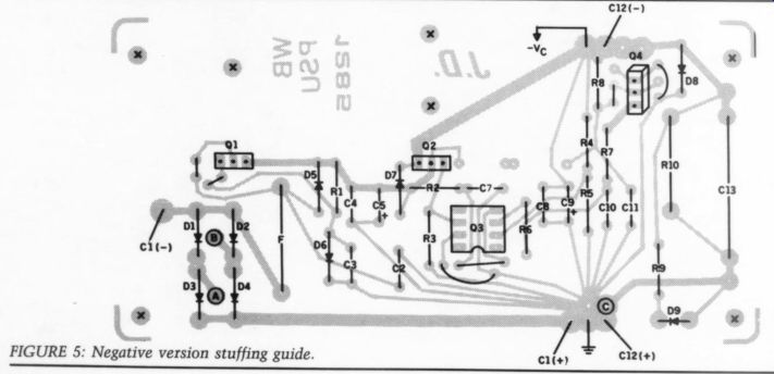
Figs 3-5.
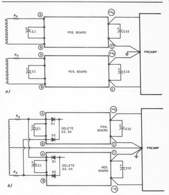
FIGURE 6: To obtain best results, use two separate transformers and two positive regulator boards as connected in 6a, or follow 6b if you use existing equipment with a standard CT transformer.
Starting from the required output voltage, calculate R5. The 5V reference will appear across it, so for 15V V, and R4 being 1k, R5 = 500 ohm nominal. For a 24V supply for the Borbely preamp, R5 = 263 ohm nominal.
The preregulator output voltage should be at least 3.5V higher to en sure correct error amp operation, therefore, 18.5 or 27.5V minimum respectively. With Q1 being an 18V regulator, D6 would be a single 1N4148 diode, or a 9.5 or 10V zener respectively. The input voltage to Q1 should be some 3 or 4V minimum above the preregulator output, there fore, 23 or 32V.
One solution is to choose a transformer giving, say, 24V AC, and use R; to get the required input. This will limit the thermal stress on Q1 and the rectifiers, decrease transformer noise, and attenuate the higher harmonics in the ripple voltage on C1--important for a clean pre-regulator output. Typical values for R, range from 0.5 to 10 ohm at several watts dissipation. Note you must select the rectifier diodes according to the required output current.
Construction Hints
Power supply construction is extremely simple. After you make the required decisions as outlined in the previous section, board stuffing will take little time. Be careful, however, with capacitor and diode polarities.
Note the polarity for D6 is indicated correctly on the stuffing guides for a zener diode. If you use just a 1N4148 or equivalent, reverse it. Connect the large input and output electrolytics with short, heavy gauge litz. If you want to keep the AC parts in a separate box, make sure it will enclose the transformer, rectifier bridge and the input electrolytic. You can then omit D1-D4 from the board, and connect the raw supply to the C1 pads. Mount the board as close as possible to the circuit to be fed. The supply has an output impedance of less than 0.01 ohm at 100kHz. Five inches of hookup wire may triple this number. If you can, mount C13 on the ] preamp board instead of on the supply board, as close as possible to the actual circuitry.
Good luck, and enjoy your music.
REFERENCES
1. Sulzer, Michael P., “A High Quality Power Supply Regulator for Op Amp Preamps, ” TAA 2/80.
2 Breakall et al, “Measuring Power Supply Output Impedance, ” TAA 1/83.
3. Sulzer, Michael P., “Regulators Re visited, ” TAA 1/81.
By Jan Didden
----
Also see:
IMPROVING LOGICAL SYSTEMS 1081 ANALYZER, By Terry Smith