SINCE WRITING MY ORIGINAL ARTICLE on Magnavox mods, I have continued to investigate the inner workings of Philips' version of digital audio reproduction. I now believe you can arrive at a new level of accuracy in CD reproduction, based on the changes I present here.
Most of the changes take place in the DAC section. Originally I changed the DAC capacitors to values in graduating increments from 0.01uF to 1uF in ten steps.
After Jung and Childress proposed all 1uF caps on the TDA1541 dual 16 bit DAC, I tried the same with the TDA1540 14-bit DAC. I was pleased enough to include this in my article. I had noted increased dynamics as the main benefit.
Then I built a new preamplifier a la Borbely's wonderful design. Since that time I have noticed a skewed frequency spectrum with harshness in the upper frequencies. Based on my previous experience with graduating values of capacitance and their influence on frequency balance, I decided to try a combination of 1uF, 0.1uF and 0.01 uF in parallel. Magic! I now had the dynamics and frequency balance right. Dire Straights' Brothers in Arms CD now sounded clean-the cymbals and snare were more identifiable and distinct.
Sloppy but Beautiful
My advice is to use the smallest voltage/ package size polypropylene or polystyrene caps you can fit. Follow Table 1.1 mounted mine on the trace side of the board anywhere I could pick up ground and the ten pins of the DAC. I also suggest the component side across the DAC itself, or anywhere you can fit them.
This sounds sloppy and it is. But, oh. . . the sound.
The second change is to replace the Philips + 5V filter and decoupling caps at the DACs. Refer to your manual for their locations and replace them (ID 2558, 2559, 2562, 2593, 2594 and 2597) with 330uF low ESR axial electrolytic capacitors paralleled with 0.1 and 0.01 uF poly types (Panasonic HF and P Series from Digi-Key). The area around the DACs is getting crowded, but fit them where you can.
As I was poking around with an oscilloscope looking at all the signals and sup plies (very educational), I noticed the +5V and + 12V Magnavox power supplies had a 40 to 50mV "wobble." Initially I was perplexed, but I finally realized, after hitting the ''Stop'' button,
----------------
ABOUT THE AUTHOR
John Allgaier, 37, is married with three children and lives in Kalamazoo, MI. An engineering technician with Allen Test products for the last six years, he has also worked as a biomedical tech and in radio-telephone repair.
------------
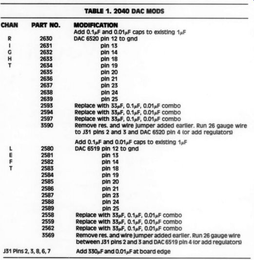
TABLE 1. 2040 DAC MODS
--------
Add 0.1uF and 0.01 uF caps to existing 1uF DAC 6520 pin 12 to gnd pin 13 pin 14 pin 18 pin 19 pin 20 pin 21 pin 23 pin 24 pin 25 Replace with 33 uF, 0.1uF, 0.01uF combo Replace with 33uF, 0.1uF, 0.01 uF combo Replace with 33 uF, 0.1uF, 0.01uF combo Remove res. and wire jumper added earlier. Run 26 gauge wire to J31 pins 2 and 3 and DAC 6520 pin 4 (or add regulators) Add 0.1uF and 0.01uF caps to existing 1uF 2580 2581 2582 2583 2584 2585 2586 2587 2588 2589 2558 2559 2562 3569 pin 13 pin 14 pin 18 pin 19 pin 20 pin 21 pin 23 pin 24 pin 25 DAC 6519 pin 12 to gnd Replace with 33uF, 0.1uF, 0.01uF combo Replace with 33uF, 0.1uF, 0.01uF combo Replace with 33uF, 0.1uF, 0.01 uF combo Remove res. and wire jumper added earlier. Run 26 gauge wire between J31 pins 2 and 3 and DAC 6519 pin 4 (or add regulators) J31
Pins 2,3,8,6,7 Add 330uF and 0.01uF at board edge
TABLE 2. DAC +/- 5V REGULATORS
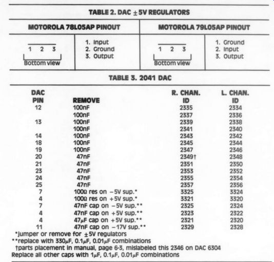
MOTOROLA 79LO5AP PINOUT
R. CHAN.
REMOVE ID 100nF 2335 100nF 2337 100nF 2339 100nF 2341 100nF 2343 100nF 2345 100nF 2347 47nF 2349t 47nF 2351 47nF 2353 47nF 2355 47nF 2357 1000 res on -5V sup.* 3325 1000 res on +5V sup." 3321 47nF cap on -5V sup.** 2325 47nF cap on +5V sup.** 2323 47yF cap on +5V sup.** 2321 1" 47nF cap on -17V sup.** 2329
*jumper or remove for +5V regulators
**replace with 330 uF, 0.1uF, 0.01 uF combinations
-- parts placement in manual, page 6-3, mislabeled this 2346 on DAC 6304
Replace all other caps with 1 uF, 0.1, 0.01,F combinations
New Supplies
I still was toying with the idea of new + 5V supplies for the DACs, but was against a second ''box'' hanging behind the player and initially did not want to regulate from my new + 15V analog supply. I went back to the service book and traced the + 5V supply lines; they ran along the center of the circuit board full length, across the front, and down the left side to the back of the board before feeding the DACs-three inches from where they entered! I removed the 100 ohm resistors (3569 left, 3590 right) and my jumper wires across these resistors that I added in earlier mods, then ran 26-gauge wirewrap wire from the +5V pin (31-2+3) at the supply connector to each DAC individually. I looked at the - 5V traces and saw they came straight to the DACs. By isolating these + 5V runs to the DACs, I eliminate the switching currents caused by the other chips from influencing the voltage seen by the DACs.
The power supplies still had the aforementioned wobble, though, and I was not satisfied. Since then I have added + 5V regulators that I run from the + 15V analog supplies. I used 78L05 and 79L05 packages. You must remove the 100 ohm resistors and any wire jumpers added, to disconnect the + 5V lines. Cut the -5V feed trace coming to pin 7 of the DACs (leave the traces going to the decoupling caps connected). Hook the output of the regulators directly to the DACs. Musically, this is equal to changing to better op amps. Another veil is lifted from the music, and I highly recommend this easy mod. See Table 2 for the pinouts of these regulators.
When I purchased the 16-bit CDB-560 Magnavox player, I noticed much more bass response. Pondering why, I questioned the DC servo amp response in the 2040's analog section. The 1M ohm / 0.1uF combo gives a corner frequency of 1.63Hz, a fairly high point for DC correction. A megohm with 1uF moves the corner frequency to 0.16Hz, a 6.3sec time constant. This produces so much more bass response that I recommend changing the two servo caps to 1uF, and R3/R6 to 10k, for more offset control. These are on Piggyback #1 and #2.
The 10-2041-1051 Models
Since my article in TAA 4/88, I received a plea for help from Gary McKenzie on his 2041. When I wrote about my 2040 model, I had no information on the X041-51 players and no access to one for design work, but I wanted to share the information with those owners. Gary was kind enough to lend me his manual
TABLE 4. 2041 EASY MOD
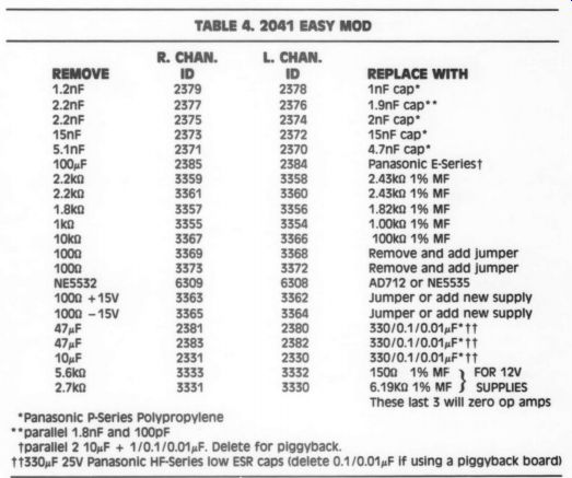
*Panasonic P-Series Polypropylene
**parallel 1.8nF and 100pF
parallel 2 10 uF + 1/0.1/0.01uF. Delete for piggyback.
330 uF 25V Panasonic HF-Series low ESR caps (delete 0.1/0.01 uF if using a piggyback board)
---------------
PARTS LIST
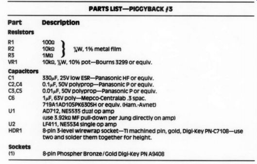
-PIGGYBACK #3
Description 1000 10ke 1M ohm
%W, 1%metal film 10k@, %W, 10% pot-Bourns 3299 or equiv.
330uF, 25V low ESR-Panasonic HF or equiv. 0.1uF, 50V polyprop-Panasonic P or equiv.
0.01uF, 50V polyprop-Panasonic P or equiv.
1 uF, 63V poly-Mepco-Centralab .3 spac.
719A1AD105PK630SH or equiv. (Ham.-Avnet) AD712, NE5535 dual op amp (use 3.92ka MF pull-down per Jung directly on amp) LF411, NES534 single op amp 8-pin 3-level wirewrap socket-TI machined pin, gold, Digi-Key PN-C7108-use two and solder them together for height.
8-pin Phospher Bronze/Gold Digi-Key PN A9408
-------------
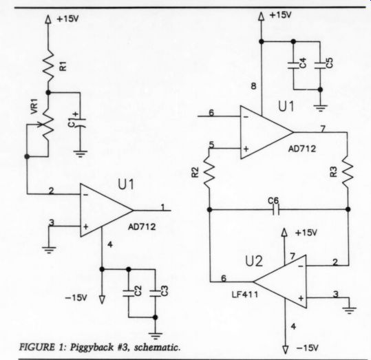
FIG 1
(NAP seems to be out) and, well, with encouragement from TAA, here we go! Again, I caution you to work carefully, read the whole article, and understand what you are to do before you start work on your player. A reminder: you will void any warranty on your player.
DAC Improvements
All my comments on sonic improvements in the original article, plus the up date (TAA 1/89, pp. 52 and 53), apply here. Don't be afraid to work on surface mount parts. Use a decent solder "'sucker'' and a small pry tool to remove the caps and resistors. Radio Shack carries both a vacuuming sucker and a bulb desoldering iron. If you are going to add an analog supply I highly recommend the +5V regulators. Follow the part number outlines in Table 3. If you have a player other than the 2041, double
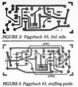
FIGURE 3: Piggyback #3, stuffing guide.
check the schematic for your player. Add the capacitors directly to the pins of the DACs. I considered a raised board for the caps, but because of the proximity of the two DACs this is nearly impossible.
Easy Mod
Again, refer to my original article and POOGE the analog section. Follow the listing in Table 4 and work very care fully. I would add the pull-down resistors to the op amp outputs per POOGE-4 [2] for an improvement in the amps. Also add the bulk capacitance to the + 12V sup plies wherever you can find room.
Piggyback #3
Piggyback #1 will become Piggyback #3 (Figs. 1-3), as a new circuit board is needed. This board can be used in any op amp location in any player that uses a pin-compatible NE5532-type amplifier.
There is a LF411-type location for servo control of the output voltage. The components necessary to eliminate the 0.8V output voltage on the amps caused by the DACs were changed in Table 4, as these parts were included in the original 2041 Philips artwork and circuit. Don't stuff these on the Piggyback #3 circuit board unless you want to use the potentiometer to exactly zero the pin 1 outputs of the amps, in which case delete parts 3330-33 and 2330-31 from Table 4.
If you choose not to use a piggyback board and have an AC-coupled preamp, or wish to eliminate the output capacitors, measure the output voltage-with these components and a + 12V supply (496 tolerance) the voltage will vary from 4.6mV to 180mV. If the value is too high, AC couple or use the formulas given in the Piggyback #1 section (TAA 4/88) to
--------------------------
TABLE 5.
REMOVE ID
ID ADD COMMENTS
100uF 2385 2384 wire
Jumper capacitor 10k 3367 3366 on an
Delete any part here 1000 3369 3368
Wire Jumper resistor 1000 3373 3372
Jumper resistor NE5532 6309 6308
Add piggyback last
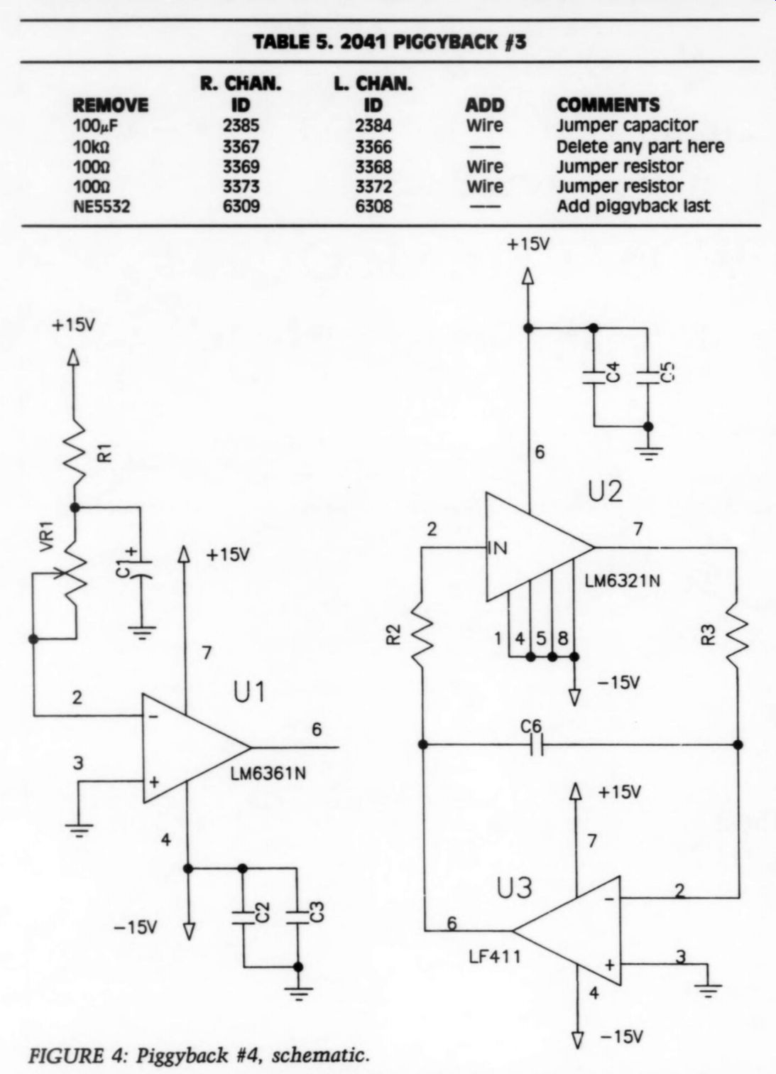
FIGURE 4: Piggyback #4, schematic.
-------------------------------
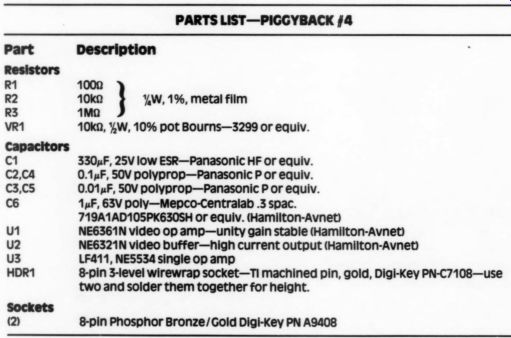
PARTS LIST--PIGGYBACK #4
Part Description
Resistors R1 1000 R2 10k %W, 1%, metal film R3 1M-ohm VR1 10k, %,W, 10% pot Bourns-3299 or equiv.:
c1 330uF, 25V low ESR-Panasonic HF or equiv.
0.1 uF, 50V polyprop-Panasonic P or equiv.
0.01uF, 50V polyprop-Panasonic P or equiv.
C6 1uF, 63V poly-Mepco-Centralab .3 spac.
719A1AD105PK630SH or equiv. (Hamilton-Avnet)
U1 NE6361N video op amp-unity gain stable (Hamilton-Avnet)
u2 NE6321N video buffer-high current output (Hamilton-Avnet)
u3 LF411, NES534 single op amp
HDR1 8-pin 3-level wirewrap socket-TI machined pin, gold, Digi-Key PN-C7108-use Sockets 2 8-pin Phosphor Bronze/Gold Digi-Key PN A9408 12
play with the 150 ohm and 6.19 k-Ohm values to eliminate any objectionable offset. You could use a 10k pot for the 6.19k-o resistor, but I won't guarantee its long term stability without the use of a servo amp. The relays I mentioned in Piggyback #1 are not needed; Philips uses transistors to short the outputs during mute. Follow Table 5 for analog section POOGEing after completing the DAC and Easy Mod sections.
Piggyback #4 This section corresponds to the Piggy back #2 section in the original article.
The new Piggyback #4 circuit board (Figs. 4-7) also works in any NE5532 type op amp position where you want high-performance amps and servo control. The offset cautions are the same as in Piggyback #3.
I have been experimenting with anew line of video op amps from National and am very pleased with the results. have laid out this PCB to take advantage of these new amps. At the I/V converter stage I am using the LM6361 video op amp. This amp is unity gain stable, good to 50MHz, with a slew rate of 300V/uS.
The major improvement over the Harris chip is in ambient information (the two chips are pin compatible, but you must remove the 20pF cap on pin 8 of the Harris chips). For the LP filter buffer stage I am using the LM6321 video buffer chip.
This baby is great! It can drive 50Q high capacitance cable (sound familiar?) with + 300mA of current. It slews at + 800V/ uS. To use this buffer in the Piggyback #2 board you must make a jumper block to convert the LM6321 pinout to the Harris op amp pinout. Refer to Table 6 for the pin conversions. The LM6321 will drop into Piggyback #4.
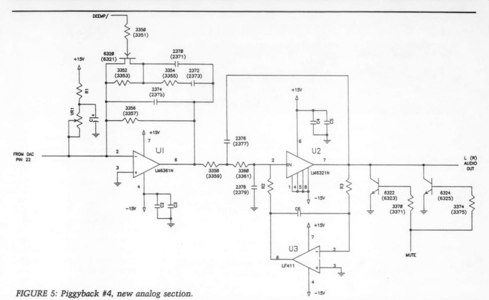
FIGURE 5: Piggyback #4, new analog section.
More Mods
A few areas can still be improved. You can perform these mods independently of each other.
POOGE the +/- 12V supply capacitors with low ESR Panasonic HF-Series types.
Use 1,000uF, 25V values at ID 2418 and 2419; use at least 470uF, 16V values at ID 2412 and 2413. For the raw - 5V supply.
Seri PUES 5 A00F, 16-V HF Suties cop ot 1D 2417; this also supplies the tracking circuitry. At the + 5V regulator outputs use at least 470uF, 16V caps at ID 2410 and 2411.
Change ID 2414 to a 330uF, 25V
The digital decoding chip set also runs off the +12V supplies, isolated by a diode drop. For a noticeable improvement, build a separate +15V analog supply and inject the voltages where you remove the supply resistors (or jumpers) at ID 3362-65. You must recalculate the DAC resistors to zero the l/V stage. Regulate the new + 15V with the 78L05 79L05 regulators for a definite DAC improvement and insert these voltages where you remove the supply resistors to the DACs (ID 3320-21 and 3324-25). Re member, supply 115V AC to the new supply at the same point as the Magnavox transformer so both are switched at the same time.
As for headphone volume, resistors 3376 and 3377 (1502) can be lowered to increase the level. I warn you again--a little goes a long way.
Conclusions
I hope this gets another group of hesitating POOGERS on the path. My new piggyback designs, especially PCB #4, will be useful on all 14-bit, 16-bit and possibly other brands of players that use the standard dual op amp pinout package, limited only by the size of the board.
Apply these techniques to the 16-bit machines-I'm starting on my ''new'' bargain CDB-560 when this is finished.
I was totally surprised at the extra ambient information a stock 16-bit player gives compared to my modified 14-bit Are all these mods necessary? I think so. Will they cure all CDs ills? I think not, but your collection of CDs will again be an adventure of discovery.
When POOGE techniques are applied to the A/D process, along with the higher sampling rate conversion, we may see digital reach its full potential.
I am now pleased with the sound of my system. I have experienced J. Gordon Holt's ''goose bump'' reaction with the right source material. What more can you ask for!
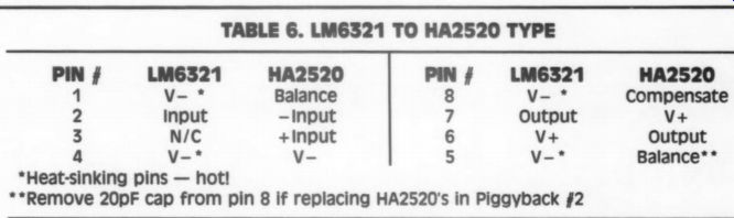
TABLE 6. LM6321 TO HA2520 TYPE
* Heat-sinking pins - hot!
** Remove 20pF cap from pin 8 if replacing HA2520's in Piggyback #2
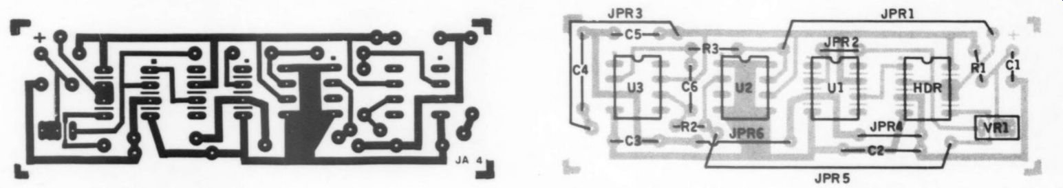
FIGURE 6: Piggyback #4, foil side.
FIGURE 7: Piggyback #4, stuffing guide.
3-LEVEL WIREWRAP PIGGYBACK PCB SOLDER CD PLAYER PCB
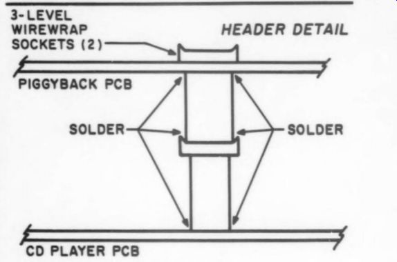
FIGURE 8: Header detail.
HEADER DETAIL
I wonder what Yamaha's 18-bit players sound like? What about Analog Devices' new AD1860 18-bit DAC mated with a Yamaha?--a true 18-bit synthesis.
Since writing this article in TAA 89,1 have tried Walt Jung's NE530 resistor trick from POOGE-4. I am really pleased with the sound of this combination. The LM6361s are more dynamic and 'clean' sounding, but the NE530 with resistors have a tonal accuracy, dimensionality and "'rightness'' I cannot deny. I now use these amps in both my 14- and 16-bit players. Mount the resistors directly on the NE530 and use in U1 on Piggyback #4. Thanks again to Walt.
REFERENCES
1. Allgaier, John, ''Greening Magnavox 14 bit CDs,'' TAA 4/88.
2. Jung and Childress, ''POOGE-4: Philips/ Magnavox CD Player Mods, Part],'' TAA 1/88 (also see part IT, TAA 2/88).
SOURCES
caps, resistors, cable, AD712 and NE5535:
Old Colony Sound Lab
PO Box 243 Peterborough, NH 03458-0243 (603)-924-6371
caps, resistors, sockets, 7XL05 regulators:
Digi-Key Corporation
701 Brooks Ave. South PO Box 677
Thief River Falls, MN 56701-0677 (800) 344-4539 LM6321N, LM6361N, Signetics
CD ICs:
Hamilton-Avnet 2215 29th Street S.E.
Space A-5 Grand Rapids, MI 49508
Offices (616) 243-8805
For Area/Regional Sales:
Hamilton-Avnet National Headquarters (213) 558-2994
If there is sufficient reader interest Old Colony Sound Lab will make the circuit cards and a kit of parts available for this project. Please use Fast Reply No. 427 if you are interested in boards only and Fast Reply No. 428 if you want boards and a kit of parts.
Also see:
Feed Forward Error Calibration
A SIMPLE HIGH-QUALITY CD OUTPUT AMP, By Jan Didden