FEEDFORWARD ERROR CANCELLATION IS a technique for improving some amplifier distortion and noise problems. The technique was patented by Harold S. Black in 1929 [1] and predated his invention of feedback by several years.
Feedforward has been used sparingly in radio frequency (RF) amplifiers and even less in audio probably because it is complex and expensive compared with other techniques. Like the other techniques, feedforward is not a panacea for all distortion and noise problems but could be a powerful tool a designer might use in combination with others once he understands its strengths and weaknesses.
Introduction
Many techniques are available to mitigate solid-state and vacuum-tube amplifier distortion. A list of more esoteric techniques would include multiphase push-pull, constant-voltage current amplification, pre-distortion and feed-forward. More common ones are class A bias, push-pull and negative feedback.
Of these, feedback is probably the most universally used although it has been only relatively recently that we have begun to appreciate how feedback, if it is misused, can have a degrading effect on amplifier sound. Each of these techniques deserves an article by itself but we will focus here only on feedforward and just touch on negative feedback.
----
ABOUT THE AUTHOR Ron Bauman lives in Washington, DC with his family, Marcia, Marcus and Mitchell. He is a graduate of Lehigh University where he received a BSEE. His interest in feedforward began over ten years ago while conducting research on communications systems, but he has been working on audio design as a hobbyist since he was ten years old. He holds three patents on feedforward applications.
--------
Seidel, who is one of the most prolific proponents of feedforward error correction for RF applications, has argued that "The problems and limitations of feedback arise in its skirting a--causality in at tempting to use a processor's output to amend the processor's performance to yield a more acceptable output. There exists a need to blur time, and yet not violate causality, and this is the precise subject matter of the stability and performance capability of feedback.'' [2] Ideally, a feedback amplifier would have no transit delay so that its output could appear back at its input before the input signal changed state.
Otala [3] has shown that transient inter modulation (TIM) can occur when the input signal increases sufficiently fast and the feedback signal takes too long to get back to the input. When that hap pens, the first amplifier stage goes into overload for a brief but audible period of time during which excessive intermodulation distortion occurs. His work showed how to design TIM-free amplifiers and resulted in a general conscious ness-raising (of some within the audio community) about the limits of feed back even to the extent that a lack of feedback, especially overall feedback, is now considered a design virtue.
Feedback
Although negative feedback is present in most amplifier designs, overall feedback is rarely used in non-inverting amplifier designs. To illustrate, let's consider the topology of a typical power amplifier.
Referring to Fig. 1, the feedback loop includes the second, Q2, and subsequent stages leaving the first stage, Q1, with either local emitter, source or cathode degeneration (degeneration is a form of negative feedback generally applied to a single active device) or no correction at ...
------------------
FIGURE 1: Non-inverting feedback amplifier.
--------------
... all as in Fig. 1. One final drawback worth mentioning is that feedback, like most of the other distortion mitigation techniques previously mentioned, does not generally give the designer much control over signal-to-noise (S/N) performance and, in fact, generally degrades S/N.
Todispel any notion that am going to indulge here in a feedback bash, let me acknowledge that feedback has been applied successfully in some very fine sounding amplifiers, so I have no doubt it can be very effective especially when used in conjunction with other properly applied distortion mitigation techniques, good components and circuit topologies. In fact, feedforward circuits would be very difficult to practically implement if it weren't for some of feed back's positive qualities such as its ability to stabilize the gain of an amplifier, reduce output impedance and create virtual ground nodes within signal paths.
We will see later how these qualities help avoid unwanted feedback and coupling within feedforward circuits.
In contrast to his comments on feed back, Seidel observes that ''Feedforward ... attempts to abide strictly by causal precepts' and I will soon describe how feedforward deals with time delays inherent in amplifiers, in order to ''abide by causal precepts'' ; the inability to deal with that seems to be feedback's main weakness.
Feedforward to the Rescue
Feedforward can overcome many of feedback's main problems. It can enhance signal-to-noise ratios (S/N), does not re quire especially fast amplifiers to avoid secondary distortion effects like TIM (although we will see that fast transit time improves the performance of feed forward for other reasons), and can easily be applied to encompass all active amplification stages.
-----------
-------------
But, before you get the idea that feed forward is perfect in practice, let me point out a few of its flaws. First, feedforward uses a second amplifier to amplify the error signal thus adding complexity and expense. Moreover, the distortion and noise of the second amplifier will appear at the output (although with proper care, it can be made less than that of the main amplifier). Second, as we shall soon see, feedforward requires that ac curate time, phase and amplitude tracking be maintained over the many octaves of bandwidth covered by an audio amplifier even though these parameters change with time, temperature, humidity and possibly with the frequency and amplitude of the amplified signals.
Nevertheless, feedforward has been successfully applied to RF amplifiers to reduce distortion by several orders of magnitude and noise by more modest amounts. Feedforward should work in music signal amplifiers (although the ten octaves comprising the audible spectrum are much greater than the fractional-octave bandwidths usually associated with RF amplifiers), and in fact, Vanderkooy and Lipshitz published some years ago a detailed exposition on feedforward error cancellation including several applications to audio frequency amplifiers.
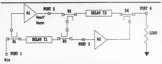
FIG. 2
If you want to dig deeper into the subject, their references are a comprehensive list of important papers in the area and their article provides an excellent tutorial on the subject of feedforward and on a few variations on the basic theme.
Two commercial feedforward amplifiers are available, one by QUAD, which uses a variation of feedforward called current dumping, [6] and one by SANSUI, [7] which appears to be based on a variation of Sandman's. In both of these applications, feedforward is applied only to correct the final output stage and not the en tire power amplifier. The Vanderkooy and Lipshitz article covers the QUAD current dumping technique in some detail and also touches on the Sandman variation.
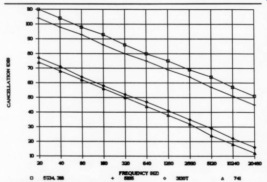
FIGURE 3: Feedforward cancellation limits.
No Guarantees
It should be possible to apply feedforward to an entire amplifier and achieve significant improvement in measured distortion and noise. However, since the parameters we currently measure, presumably to characterize the sound we should expect from an amplifier, do not reliably correlate with what we hear, or like to hear, we cannot assume that by simply reducing measured distortions we will obtain a more pleasing or acceptable amplifier. And this brings us to the purpose of these articles.
I have three aims: to equip the audio amateur with a practical understanding of the principles of feedforward error cancellation, to apply those principles in designing circuitry we can listen to, and most importantly, to provide a forum for reporting the results of our listening evaluations.
Feedforward is not perfect and because of practical limitations in implementing any design, we may expect feedforward to introduce some sort of coloration. The questions are: ''Are its colorations tolerable?" and Is the resulting sound pleasing and competitive with the sound of amplifiers using other circuit techniques?'' In short, the purpose of this series of articles is to determine whether feedforward can help contribute to our enjoyment of reproduced music.
Principles
The term feedforward is often applied to a circuit technique for enhancing band width in which the higher frequencies in a multistage amplifier are fed around (fed forward) a bandwidth-constraining amplification stage. In this way, the overall frequency response of an amplifier can be enhanced. This article does not address that kind of feedforward. Here we are concerned with a more complex technique for cancelling errors produced in the amplification process.
Feedforward error cancellation operates in two sequential steps. First, a distortion and noise sample, called the error signal, produced by the main amplifier, is isolated from the signal. This error signal is then amplified in a second amplifier and combined with the output of the main amplifier so that the error signal is cancelled at the output. Here is how it's done.
Figure 2 is a simplified block diagram of a feedforward amplifier. (The two symbols, D and T in Fig. 2, stand for directional coupler and time delay and are not usually found in audio schematics. We will use them only to explain the basic theory and then replace them as we go with more easily implemented and more familiar circuitry.) An input signal, Vin, enters the amplifier at port 1 where it is split into two (not necessarily equal) parts, each headed for the input of amplifier A2 at port 3. One part takes the path D1-A1-D2-D3 and the other takes the path D1-T1-D3. T1 is a time delay with ...
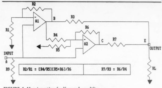
FIGURE 4: Non-inverting feedforward amplifier.
... the job of assuring that signals taking the two paths from port 1 to port 3 arrive at port 3 at the same time.
The output signal of A1 is represented as two terms, Vou' and Ven, where Vou' is a perfectly amplified but delayed (by the transit time of Al) replica of the in put signal and is called the desired or fundamental signal, and Vr represents the error signal (distortion and noise) produced by A1. D2 and D3 couple a portion of Vou' and Ver to port 3 and adjust their amplitudes and absolute phase so that when Vou' and Vr collide with V1, (delayed by T1) at port 3 the fundamental signal cancels its amplified counterpart.
All that is left after cancellation is a replica of Ver. This completes step 1, the isolation of the error signal.
Step 2 is much like step 1. Just as the input signal was split and took two paths from port 1 to port 3, Vou' and Ve are split at port 2 and take two paths to port 4, the output port. One path is D2-T2-D4 and the other is D2-D3-A2-D4. As in step 1, T2 delays the signals in its path so that they arrive at port 4 at the same time as their counterparts taking the path D2 D3-A2-D4. Since the output of A2 consists (ideally) only of the amplified error signal, and the signal at the output of T2 consists of both the fundamental and error signals (appropriately delayed), the error signals cancel and we are left with only the fundamental signal.
Practicalities
In theory we can get perfect cancellation of the error signal, but as we have seen, to do so requires a time delay to compensate primarily for transit time delays through the amplifiers. However, if the delay through the amplifier is small enough we may still be able to obtain significant cancellation performance without time delay compensation. To get an idea of the amount of cancellation achievable with no time delay compensation, I recorded data on a feedforward amplifier using various op amps for A1.
Figure 3 plots the data taken with steady state sinusoids and shows that significant cancellation of the fundamental signal can be obtained without time delay (or for that matter phase) compensation.
To do better than this would require either faster amplifiers or complex time and phase correction circuitry. In terms of our first design efforts, Fig. 3 tells us we could replace time delays with resistors if we are willing to accept the resulting limits in cancellation performance.
Now that we have an idea of how much cancellation we might obtain from a feedforward amplifier without time or phase compensation let's examine how to replace directional couplers with more readily obtainable components.
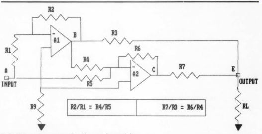
FIG. 5
Directional couplers can be quite cumbersome and expensive at audio frequencies and for those reasons we would like to avoid them, especially in our first design efforts. However, the properties of directional couplers are ideal in developing the basic principles of feedforward amplifiers because they avoid arguments about oscillations caused by inadvertent feedback loops, for example the loop from port 4 to port 4 through D4-T2-D2 D3-A2-D4 in Fig. 2. They also avoid other undesirable interactions between the feedforward elements and external signals such as power reflected back wards into the output port from mis matched loads.
Directional couplers accomplish this by coupling to the coupled port only the power that flows in a desired direction.
For example, in Fig. 2, we want a portion of the power that flows from the output of amplifier A1 to output port 4 to couple to input port 3 of amplifier A2. Directional couplers D2 and D3 accomplish this for us. But we don't want power reflected from the load at port 4, that travels backwards through directional coupler D4, to appear at the input of A2.
Directional coupler D2 assures that backward-going power is dissipated within the directional coupler and is not coupled to A2. However, we may be able to control the direction of power in another way: by creating virtual short circuits in the signal paths where we need them.
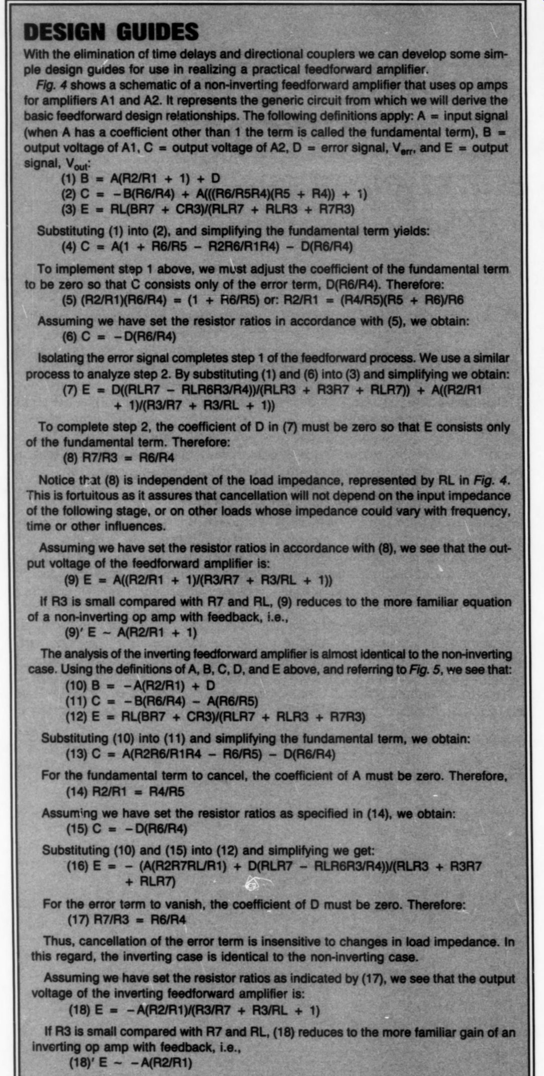
Fortunately, at audio frequencies, the output impedances of A1 and A2 can be made relatively small compared with other loop impedances so they act to short circuit undesired feedback loops and reverse going power. Amplifiers with low output impedance allow us to replace directional couplers with resistive dividers. Later I will discuss the drawbacks in using resistive dividers instead of directional couplers when applying feedforward to audio power amplifiers. The guide for designing is in the ac companying box: Design Guides.
After we have developed the design theory (see box), we are ready to consider applying it to a practical circuit. The first decision then is to what kind of circuit we will apply the theory.
Feedforward Penalties
Up to now, we have not constrained the application of feedforward, and in fact, we could apply it to any kind of an amplifier intended for linear applications ranging from pre-preamplification to high power amplification. However, as I mentioned earlier, applying feedforward to a high power amplifier using strictly resistive coupling to the load exacts a penalty. Perhaps an example is the best way to explain.
Consider Fig. 6 in which A1 is a 100W power amplifier having 0.5% distortion.
Assuming an 8 ohm load, the distortion would be 0.2V peak and the amplified error signal from A2 would need to be 0.2V peak (but of opposite polarity) at E in order to cancel A1's distortion. A2 must produce an error signal that is R7/R3 x 0.2V in order to adequately cancel its counterpart at E. In order that the output impedance of A2 not load the output of A1, and vice versa, R7 needs to be greater than the load by, say, a factor of 10. Thus R7 should not be less than 800.
To reduce the required voltage swing of A2, R3 should be as large as possible.
But, since R3 is in series with the load, it will raise the output impedance of the amplifier. So, from the standpoint of minimizing the amplifier output impedance, R3 should be minimum. A practical value for R3 might be 0.1 ohm. Thus, in our example, the voltage swing of A2 would need to be at least (80/0.1) x 0.2 or 160V peak with a peak current capability of 2A. A2 would deliver 160W to R7 when called on to cancel 0.2V of distortion and almost all of this power would be dissipated in R7.
What to Do?
Although the error amplifier in this example could be built, the idea of using a 160W amplifier to correct the distortion of a 100W amplifier seems inefficient (especially when considering that the power needed to cancel the distortion is only 2.5mW!). I therefore wouldn't recommend implementing such a design. A directional coupler that replaces R3 and R7 would allow a design that avoids most of this inefficiency but, as we mentioned earlier, directional couplers have their own sets of not easily overcome problems, when applied at audio frequencies.
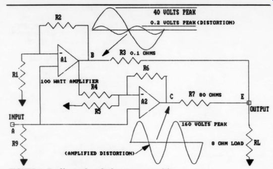
FIGURE 6: Feedforward applied to power amplifier.
So, to avoid the problems in applying feedforward to a high power amplifier (for the moment anyway) we will concentrate on applying it to a low power unit such as a line amplifier.
The first design step is to select op amps for A1 and A2. Many options will work satisfactorily here and the amps need not be of the same type. In fact, each feedforward op amp can be chosen to selectively optimize different, and perhaps ordinarily opposing, performance parameters, the combination of which would be difficult to achieve in a conventional amplifier. The ability to combine otherwise opposing design features is a unique characteristic of feedforward amplifiers which other techniques cannot readily match.
For example, if we desire both low noise and balanced circuit topology (balanced topology because it presumably yields lower overall distortion than un balanced topologies) we can use a low noise op amp, such as a 5534, for A2 while a 5195, which has a balanced complementary /differential topology, but much greater noise than the 5534, can be used for the main amplifier, A1. The resultant feedforward amplifier will then exhibit the low noise performance of the 5534 and the low distortion characteristics of the 5195.
The next consideration in designing our line amplifier is choosing its voltage gain. We are of course free to choose any gain we wish, but, for this example, I arbitrarily choose a voltage gain of positive 11. Referring to Fig. 7, the gain choice of 11 sets the ratio of resistor R2 to R1 at 10 (recall that the gain of a non-inverting op amp is R2/R1 + 1). The next step is to determine the values of R1 and R2. Assuming DC coupling to the preceding amplifier stage, minimum DC voltage offset and drift occurs when R1 (in parallel with R2) is equal to the DC output impedance of the preceding stage. We assume 4220 for R1 which sets the value of R2 at 4,2200.
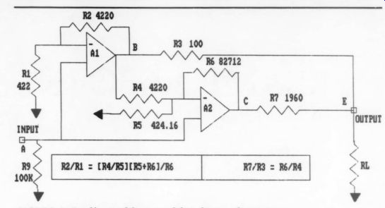
FIGURE 7: Feedforward line amplifier, basic schematic.
Next we choose the value of R9 which sets the value of the input impedance of the line amplifier. R9's value is not critical (assuming DC coupling to the previous stage) so long as it does not significantly load the previous stage. If DC coupling is not used, then the parallel combination of R2 and R1 should be equal to R9 to minimize DC offset and drift. Since we have assumed DC coupling we choose 100k-ohm for R9.
R3's value should be much greater than the output impedance of A1 in order to assure that feedforward correction currents are not shunted by the low output impedance of Al, yet it should be much smaller than the load presented by the input impedance of the following stage in order to minimize signal loss.
Assuming the output impedance of A1 is less than 10, and that the input impedance of the following stage is greater than 10k, we choose R3 to be 1000. R7 presents a load to A2 and A1 and its value must therefore be great enough not to distort their outputs yet be small enough to minimize the voltage swing required of A2. I choose R7 to be 1,96090.
The ratio of R7 to R3 is therefore set at 19.6. Referring to (8), we see that the ratio of R6 to R4 should be the same as R7/R3. We can choose either R4 or R6 in dependently. However, as R4 is part of the load on Al, it must be large enough to avoid creating significant distortion in A1. If R4 is too large then R6 could be come large enough so that stray capacitance becomes a problem. To minimize both problems we select the value of R4 at 4,220. Thus, from (8), the value of R6 is set at 19.6 x 4,220 or 82,7120.
So far, we have selected or derived the values of all the resistors in Fig. 7 except R5. Rearrange (5) to solve for R5:
(19) RS = R1 R4 R6 / (R2 R6 -R4 R1)
Substituting the values we have obtained for R1, R2, R4 and R6 into (19) yields a value for R5 of 424.160.
Design Variables
Given the needed accuracy of the feed forward line amplifier resistors we have chosen, it will be difficult to obtain the exact and matched ratios, as demanded by equations (5) and (8), with fixed resistors. Instead, we can make some of them variable and adjust them to achieve the best overall cancellation. The designer must then decide which resistors to make variable.
We can get some guidance by referring to (5) and (8) and recalling that (5) sets the balance conditions for the fundamental cancelling loop and (8) sets the conditions for the error cancelling loop. As R4 and R6 appear in both equations, it would be wise to keep them fixed, otherwise the loops would interact and therefore be difficult to balance. R1, R2, and R3 are in the signal path which should be free of potentiometers, if possible, to avoid rectifier distortion that such devices can produce. That leaves R5 as the variable component for the fundamental cancelling loop and R7 for the error loop.
The foregoing analysis and design discussion gives you all you need to design a line amplifier for any audio application.
In the next part of this series we will pre sent the construction details of the particular feedforward line amplifier shown in Fig. 7.
ACKNOWLEDGMENTS
I am grateful to my colleagues at the Naval Research Laboratory, Charles Hobbis and Richard Royce, for their inspiration and support during our decade of research on high dynamic range communication architectures and technology. That research helped lay the foundation for this article.
REFERENCES
1. Black, H.S., US Patent 1,686,792, October 9, 1928.
2. Seidel, H., 'Feedforward Technology,' Proc. 1973-ISCT.
3. Otala, M. and E. Leinonen, ''The Theory of Transient Intermodulation Distortion,' IEEE Transactions on Acoustics, Speech, and Signal Processing, Vol. ASSP-25, No. 1, February 1977.
4. Seidel, H., ''A Microwave Feed-Forward Experiment,'' The Bell System Technical Journal, Vol. 50, No. 9, November 1971.
5. Vanderkooy, J. and S. P. Lipshitz, ''Feed-forward Error Correction in Power Amplifiers,'' Journal of the Audio Engineering Society, Vol. 28, No. 1/2, January/February 1980.
6. Walker, P.J. and M. P. Albinson, ''Current Dumping Audio Amplifier," Wireless World, pp. 560-562, December 1975.
7. Takahashi, S. and S. Tanaka, "Design and Construction of a Feedforward Error-Correction Amplifier," Journal of the Audio Engineering Society, Vol. 29, No. 1/2, January/February 1981.
8. Sandman, A. M., Reducing Distortion by 'Error Add-On', Wireless World, Vol. 70, January 1973.
Also see: