UPGRADING DYNACO'S PAT-4 PREAMP is interesting for two reasons.
First, the PAT-4 is readily available at low cost. You can buy one from a used equipment dealer, flea market or garage sale or a friend might even give you one. Second, the inside is spacious and uncluttered and there are enough control possibilities to satisfy most do-it-yourselfers. I had been planning a PAT-4 upgrade as a background project when the letter from Frank Dina in “Ask TAA" (2/88) convinced me that others were also interested. As noted in Mr Galo's reply, a POOGE approach would provide little improvement because of deficiencies inherent in the PAT-4 circuit.
Still, a "quick and dirty'' upgrade is possible by replacing only the power sup ply, circuit boards, volume and tone controls and a few small components. The tone controls and filters are retained; however, since the PAT-4 panel labeling does not support a tone control defeat switch, a procedure is given to adjust the tone controls for flat response. The modifications described require some construction experience and should not be attempted without a PAT-4 manual, available from Stereo Cost Cutters (Dynaco #929018). Refer to this manual when disassembling and assembling the main unit.
I use a new 3-inch circuit board
-------------
ABOUT THE AUTHOR
Thomas O'Brien has been with the Jerrold Division of General Instrument Corp. since 1978 and is currently responsible for the development of addressable pay TV control systems, including satellite distribution of a multi-channel audio CATV service. He has a B.S. in electronic physics from LaSalle University, has written several papers and industry trade articles and has been granted five patents.
His consuming hobby is audio and he has built his own equipment since the age of 18.
------------
mounted on the original U-shaped brackets, which is easily accommodated by the PAT-4 case. In addition to the circuit boards, I replaced the tone control pots with those used in the Dynaco PAT-5, using the existing dual knobs. I no longer use the 'phono high," ''phono cer," "special" and ''tape head' inputs, or the front plate mounted input and output jacks. An Alps 31-detent switch with 1.5dB tracking accuracy and a loudness tap replaces the volume control. The power supply is a conventional full-wave split configuration that provides + 15V well-filtered, but unregulated, outputs.
Circuit Description
I dubbed my circuit the PAT-4M (Fig. 1), which incorporates design techniques previously described in TAA, but uses the latest available integrated circuit devices. The LT1028 from Linear Technology offers the best noise performance of any IC op amp on the market at 0.9nV per root hertz (less than a 50 ohmresistor) and a gain of 7 million, which assures adequate loop gain as a flat preamp. In the moving magnet (MM) phono position, this circuit provides 79dB signal-to noise ratio (S/N) in a 20kHz bandwidth referred to a 5mV signal with a cartridge connected. It is implemented as a 22dB gain (MM) or 39dB gain moving coil (MC) flat amp according to the position of the rear mounted MM/MC switch (see the Audition Notes).
The second section of the phono stage uses Analog Devices' AD711 Bi-FET op amp and half an LF412A as a DC servo, which maintains the offset of the phono stage output to less than 3mV. This section provides 12dB of gain at 1kHz and the 3180usec and 318usec breakpoints of the phono equalization characteristic.
The 75 usec breakpoint is provided by the 49900 and 0.015F network between the two sections. The calculated equalization accuracy of the phono stage is +0.009-0.013dB, with the exact values specified. With 1% resistors and 2% capacitors, the actual accuracy should be within +0.13dB.
The high-level preamp stage is composed of the AD744 Bi-FET op amp with the other half of the LF412A driving its offset pin as a DC servo. The 744 features ultra low (100pA) input current, which allows you to vary the controls without creating offset problems, and 20mA peak output current into 600Q for superior drive capability into low impedance loads. The distortion is also a very low 0.002% at 3V RMS output swing at 20kHz. The 20pF compensation capacitor maintains stability as the 744 gain approaches unity, which happens when the bass control is rotated to the full cut position.
The tone control circuit is similar to that used in the PAT-5 preamp, which provides + 10dB at 50Hz and 15kHz.
Since there is no tone control defeat switch, you must identify the flat response position of each control and tighten the knob before any connections are made. With a few exceptions, in this upgrade I use 1%, 0.25 W metal film resistors and 2% polypropylene capacitors.
Although some builders may be tempted to make changes in the component values or device types, I do not recommended it unless you thoroughly under stand the design methodology.
Before starting to work, reread the text and study the diagrams so you will avoid backtracking and rework.
Construction
When removing wires from lugs, un bend the wire while applying heat
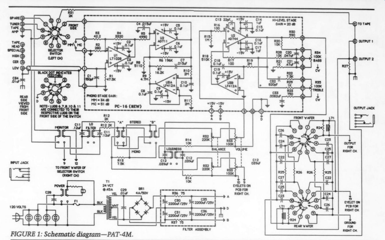
FIGURE 1: Schematic diagram-PAT-4M.
--------------
PARTs LIST
Designation
Description
RESISTORS, ,W 1%, Digi-Key unless specified 2 R3 42.20 42.2X a R16, R17 1000 100X 2 R2 2800 280X
2) R30 5900 590X
2) R23 7500 750X (CY) R21, R29 1 k-Ohm 1.00KX a R12,R31 2 k-Ohm 2.00KX 2 R4 3.32k0 3.32KX 2 RS 4.99k0 4.99KX 2 R8 5.11 k-Ohm 5.11KX (3) R13,R22 7.5k0 7.50KX
R14,R20,R28 10k0 10.0KX 2 R7 16.2k0 16.2KX
2) R1 47.5k0 47.5KX 2 R6 196ka 196KX
2) R18 510k, %W 5% 510KQ
2) R15 1M ohm 1.00MX (5) R10,R11,R19 2M ohm , YW 5% 2.0M ohm 2 R9 4.7M ohm, YW 5% 4.7M ohm 2 R36,R37 750, LW 5% 75H
"1 R33 dual 100k volume control Old Colony VR-100KJ 2 R34, R35 dual 100k tone control Stereo Cost Cutters 60104
CAPACITORS
50V 5%, Digi-Key unless specified 2 c13 22pF, 500V 5% Mouser ME232-1000-022 2 C1 0.00015 uF P3151 (2) C32 0.00082 uF P3821 2 C33 0.0082uF, 2% P3822 2 C3 0.01uF, 250V 10% E2103
P/N
0.015 uF, 2% P3153 C12 0.039.F, 2% P3393 C20 0.047yF, 2% p3473 C2,C3,C5,C6, 0.1uF, 2% P3104 C8-10,C15, C16,C18,C19 c11 0.12uF, 2% P3124 c21 0.47uF, 2% p3474 C14,C17 1uF, 25V P6771 C29 0.01uF, 1kV 20% Mouser 539-GP110 or MCM 31-1610 C30,C31,C35, 2200puF, 25V P5446 C36
MISCELLANEOUS
2 PC-16 (new) pc board 2 U1 Ultra-low noise op amp LT1028CN8
2) U2 Precision BI-FET op amp AD711JN 2 U3 Low drift J-FET op amp LF412ACN 2 U4 Precision BIFET op amp AD744JN
2) Chassis mount RCA jack DB Systems DBP-13J or Radio Shack 274-852
"1 MM/MC DPDT switch Radio Shack 275-663
"1) T1 25.2VCT @ 0.45A transformer Radio Shack 273-1366
"1) PC-T pc board
" PC-B filter mounting plate (2) 6-32 x 1" hex spacer Digi-Key J181
2) #6 fiber shoulder washer
Mouser 534-3233
2 #6 fiber flat washer
Mouser 534-3201
--------------
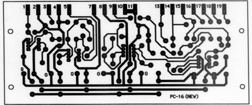
FIGURE 2a: PC-16 circuit pattern.
-------------
[...]
* When cutting wires, cut close to the lug; you can usually reuse the wire.
* Be sure to retain all hardware for reuse.
* Lug and terminal numbers I refer to are from the diagram in the Dynaco assembly manual.
Use a highlighter to record each completed step.
Main Unit Disassembly
Remove the cover, knobs and front plate.
Thoroughly clean the knobs and front plate with a reasonably mild household cleaner such as Lysol and store in a protective wrapper. You might want to soak the knobs overnight. Unsolder the connecting wires from the circuit boards, remove the hardware holding the two U-brackets and remove the boards from the brackets. Cut the wires from C29 and remove the capacitor and clamp as a unit. Remove the power transformer wires connected to lug 1 of the fuse holder, lug 1 of AC outlet B and lugs 4 and 5 of the five-lug terminal strip; remove the power transformer.
Rear Panel Disassembly
Cut the wires and PEC circuit modules from input sockets 1-5 and 12-16 and from both front and rear wafers of the selector switch lugs 2R, 3, 4, 5F, 5R, and 6-8. Remove the two 1uF capacitors (C9) between the two-lug terminal strip and input sockets 9 and 20. Remove the green wires from input sockets 10 and 11 and the black wire from the ground lug next to input socket 11. Remove the red wires from input sockets 21 and 22 and the black wire from the ground lug next to input socket 22. Remove the wires and diodes from lugs 2, 4 and 5 of the five lug terminal strip. Remove the black wire from lug 2 of AC outlet C. Remove the 13-inch green wire between lug 2 (tip) of the fuse holder and PS lug 2 and separate it from the other three twisted wires of the power switch.
-------------------
AUDITION NOTES
The following will be helpful if you are reviewing the PAT-4M.
1. The input selector has only four active positions: Phono, Tuner, Tape and Spare.
If the input selector is set to the Special or Tape Head positions, phono is selected.
2. The front panel input and output jacks are not functional.
3. Since the tone control knobs have been adjusted to produce flat response with the indicator pointing to the panel centerline, the rotation for an amount of boost or cut may vary between the four controls. Since there is no tone control defeat switch, you must set the knobs to the flat position as accurately as possible when tone modification is not desired.
4. The gold-plated phono jack pair is the only functional low-level input. An MM/MC switch controls phono gain. The MC position is marked LOW and the MM is HIGH.
5. The preamp circuit is DC coupled from phono cartridge and high-level inputs to the high-level output. The offset is less than 55 mV after a 20-minute warmup, however, if your power amp is also DC coupled, ensure the final output offset (typically less than 100mV) will not damage your loudspeakers. The unit is powered whenever it is connected to a live 115V AC source, thus the warmup is necessary only when you unplug/plug-in the unit. The power amplifier should be plugged into one of the two rear panel AC outlets that is controlled by the power switch.
6. The LO FILTER rolloff is set at 20Hz to protect the woofer cone in bass reflex speaker systems.
7. The HI FILTER is the original Dynakit version, which, when switched on causes a small amount of high-frequency degradation. This is a minor point, since the filter is normally used to reduce high-frequency content (noise) or distortion.
8. Two parallel high-level output jacks facilitate biamp or subwoofer applications.
9. You may notice a small amount of hum when the volume control is rotated fully clockwise. This results from the position of the power transformer inside the case and inadequate power supply ripple rejection. The hum should not be noticeable with the volume control in a normal listening position.
10. The tape out jack is grounded when the selector switch is in the tape position. This prevents positive feedback, which can occur when the tape deck playback output signal is fed back into the tape out jack. In addition, all unselected high-level inputs are grounded to prevent crosstalk between signal sources.
------------------
Front Panel Disassembly
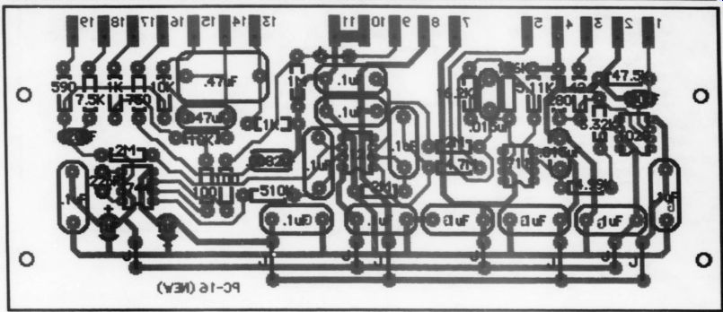
FIGURE 2b

FIGURE 2c: Drill template.
Carefully remove the two black wires from SS lug 9R of the front wafer and the two black wires from SS lug 9R of the rear wafer. Cut all the wires from the volume control, including the two 18k resistor leads, then remove it. Remove all the wires from the balance control. Save the twisted pairs to reuse on the new volume control. Mark the bass and treble controls with masking tape or a laundry marker so you can identify them, then remove them and set them aside. Do not remove the wires at this time. Cut all the wires from the output jack (OJ) and remove the other ends from FS. Loosen the shaft and rotate the switch to gain ac-cess to the lugs. Remove the parts according to Table 1.
Cut the wires from IJ lugs 3 and 4. Do not cut or remove the other ends of these wires from RS. Cut the black wire from IJ lug 1. This completes the disassembly of your PAT-4. Check your work to see if all the above steps have been performed correctly before proceeding with the assembly.
Board Assembly
Next, assemble the new PC-16 boards (Figs. 2a-c). Take a few moments to familiarize yourself with the assembly diagram and parts list, noting where each part is positioned on the board (Fig. 2b).
First, install the nine jumpers marked J on the assembly diagram using 20-gauge wire with the insulation removed. In stall the 23 resistors next. Be sure to interpret the color code correctly; 1% and 5% markings are different. Install the four ICs making sure the notch in the
--------------------
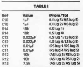
TABLE 1
Value (From/To) uF (lJ lug 5/MS lug 5) 1uF (Jug 2/MS lug 2) 18k (LSlug 1 18k (LSiug 4)
0.022uF (LSlug1/LSlug 2)
0.022uF (LSlug 4/LS lug 5)
0.01 uF (RSIug1/RSlug 2)
0.01uF (RSIug4/RS lug 5)
10k (ASlug 3/RS lug 5)
10k (ASlug 4/RSlug 2)
7.5k (AS lug 2/AS lug 5)
---------
---------
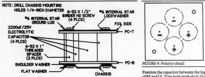
FIGURE 3: Filter assembly. FIGURE 4: Polarity detail.
-----------
package is positioned toward the bottom edge of the board. Then, install the capacitors, starting with the smallest and installing the larger ones last.
Filter Assembly
Study the filter assembly and wiring dia grams (Figs. 3-5) to become familiar with how the completed unit should look. Note the polarity of two of the capacitors is the reverse of the other two.
Mount the hex standoffs on the component side of the board PC-B with #6 screws, then install the four 2,200uF capacitors. Note there is no foil pattern for this board. PC-B is made of 20 to 22 gauge brass cadmium plated steel or tin. Use the drilling guide (Fig. 6) and insulate the assembly from ground using fiber flat washers outside and fiber shoulder washers inside the chassis.
Install the board PC-T over the other end of the four 2,200uF capacitors with the foil side up (Fig. 7a, b). Make sure the large holes in the board line up with the standoffs. Install a #6 screw and ground lug in the corner with six small holes and a #6 screw and lockwasher in the other corner. Solder both ends of the four capacitors and clip off the excess lead lengths. Bend the two 75 ohm resistors' leads to fit the closest pair of holes in each diagonal corner and install them on the foil side as shown in the diagram.
Solder these resistors on the top of the board and cut off the excess leads under the board.
Assembly
This section follows the sequence used in the Dynakit assembly manual. Most of the construction has already been done and will not be repeated. Do not trim the wires on resistor leads unless specified, since 1% resistor leads are already quite short and in some cases must be extended.
Front Panel Assembly
Install a 2k resistor between AS lug 3 (S-2) and RS lug 5. Connect the free end of the red wire from RS lug 1 to MS lug 2 (S). Connect the free end of the green wire from RS lug 4 to MS lug 5 (S). Install a 2k resistor between AS lug 4 (S-2) and RS lug 2.
Trim both leads of a 7.5k resistor to 3; inch and install between AS lug 2 (S-2) and AS lug 5. Place this resistor toward the rear of the switch. Trim both leads of a 0.12uF capacitor to 0.75 inch and install between RS lug2 (S-2) and RS lug 1 (S-2).
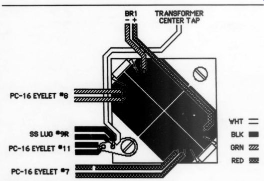
FIGURE 5: Filter wiring.
Position the capacitor between the lugs of RS and LS. Trim both leads of a 0.12uF capacitor to ¥% inch and install between RS lug 5 (S-2) and RS lug 4 (S-2). Position the capacitor between the lugs of LS and MS.
Connect one lead of a 10k resistor to LS lug 1 and connect one lead of another 10k resistor to LS lug 4.
Trim the leads of a 0.039uF capacitor to 3/4 inch and install between LS lug 1 (S-2) and LS lug 2 (S-2). Position the capacitor pointing straight toward the rear of the chassis. Trim the leads of a 0.039uF capacitor to 3/4 inch and in stall between LS lug 4 (S-2) and LS lug 5 (S-2). Position the capacitor pointing toward MS.
Install the volume control in position VC, using two 8mm nuts and an 8mm washer. The additional mounting nut is available from Mouser (#48AN008), or buy any 0.95-inch-diameter control (such as Radio Shack #271-1715) and keep the nut and throw away the control. Put one nut on the threaded bushing and then the washer. Insert the control through the panel and put the other nut on the front. Rotate the control to position the pins 30° clockwise from horizontal toward the balance control. Ad just the rear nut until the volume control shaft protrudes the same distance from the panel as the selector switch and balance control, then tighten the front nut.
The instruction sheet supplied with the Alps control shows both channels labeled 1, 2 and 3. Re-label the lugs to ward the rear panel as 4, 5 and 6. Draw two additional lugs adjacent to lugs 3 and 6 and label them 7 and 8, respectively.
Note that in this circuit, the volume control is fed from the balance control. Connect the free end of the red wire from LS lug 2 to VC lug 7 (S). Install a 2-inch black wire between VC lug 1 and BAL lug 1.
Bend the free end of the 10k resistor from LS lug 1 and one end of a 1-inch black wire into a 1/4-inch hook. Crimp the two hooks together and solder. Cover the joint with sleeving to keep it from touching the control body or the chassis. Connect the other end of the black wire to BAL lug 1 (S-2).
Install a 2-inch red wire between VC lug 3 (S) and BAL lug 2 (S). Connect the free end of the red wire from AS lug 5 to BAL lug 3 (S). Install a 1 1/4-inch black wire between VC lug 4 and BAL lug 6.
Connect the free end of the 10k resistor from LS lug 4 to BAL lug 6 (S-2). Install a 2-inch green wire between VC lug 6 (S) and BAL lug 5 (S). Connect the free end of the green wire from BS lug 2 to BAL lug 4 (S). Connect the free end of the green wire from LS lug 5 to VC lug 8 (S).
Select the red and black twisted pair previously removed from BAL and connect the red wire to VC lug 2 (S). Connect the black wire to VC lug 1 (S-2). Select the green and black twisted pair of wires previously removed from BAL and connect the green wire to VClug5 (S). Connect the black wire to VC lug 4 (S-2).
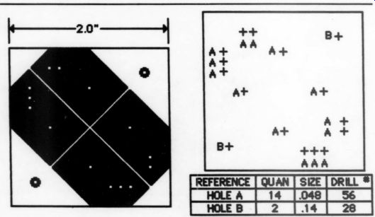
FIGURE 7a: PC-T circuit pattern. FIGURE 7b: PC-T drill template viewed from foil side.
Install the bass and treble controls with 1/4-inch nuts. Prepare a 13-inch green and black twisted pair. Loosen the
1/4-inch nut holding the filter switch at position FS and rotate the switch so that lug 9 is on top and connect the green wire to FS rear lug 9 (S-3). Rotate the switch so that lug 6 is uppermost and connect the black wire to rear lug 6 (S-4).
Rotate the filter switch to engage the locating tab and tighten the nut. Prepare a 15-inch red and black twisted pair.
Connect the red wire to FS front lug 3 (S-3) and connect the black wire to front lug 12 (S-4).
Rear Panel Assembly
Remove the tin shield and center parts of input jacks 1 and 12. Carefully drill (or ream) the phenolic center hole of each jack to 1/4 inch. Install a gold-plated 3/4 inch thread, chassis-mount RCA jack in each hole. Do not use the ground lug sup plied with the jack; you will solder the wires directly to the threaded body.
Drill a 3/4-inch hole in the rear panel centered at the ''C" in the letters CER, then scrape off those letters with a razor blade. Install the DPDT MM/MC switch so that when it is activated, the handle points to either HIGH or LOW.
Connect a 0.01 uF metal film capacitor between the bolted-on ground lug (S) and the threaded body of the bottom phono jack. Prepare a 4-inch length of coax cable and connect the center conductor to the bottom jack center lug (S). Connect the shield to the threaded body of the jack (S-2). Prepare a red and black 4-inch length of twisted pair and connect the black wire to the MM/MC switch
--------------
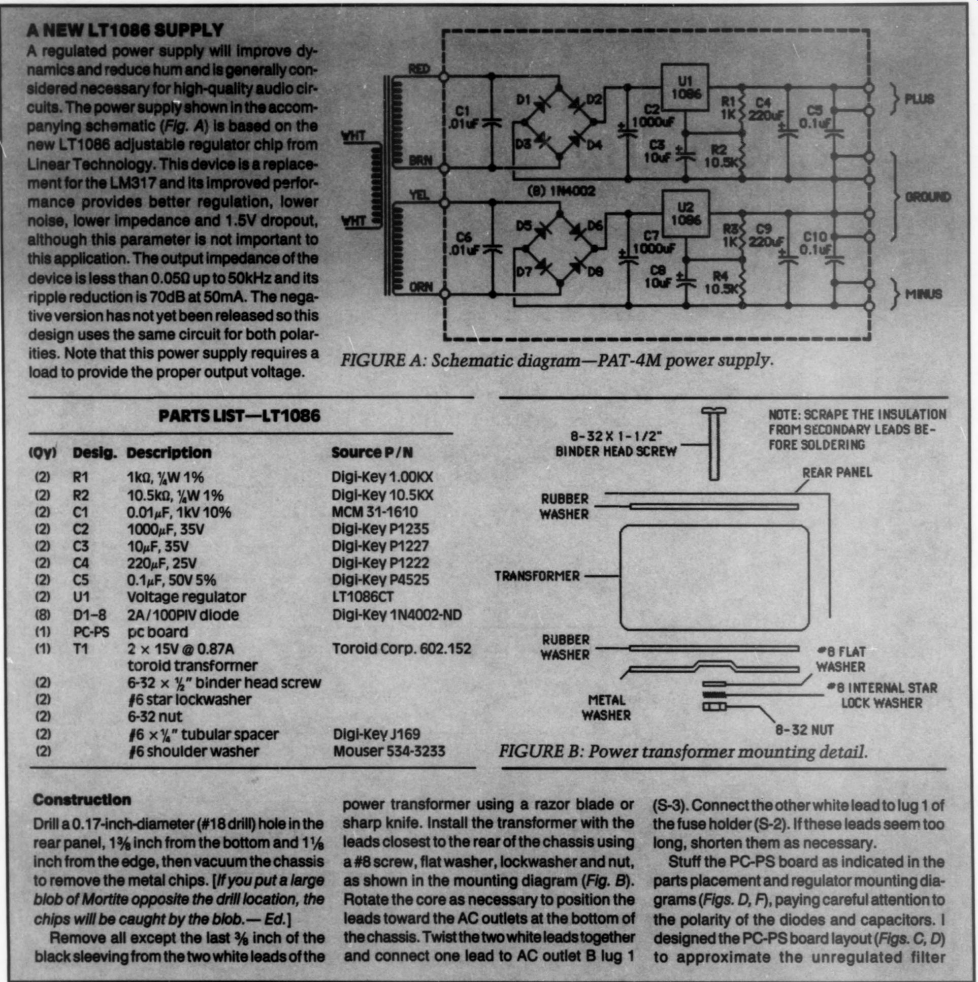
aeign set Us sare circu or ith poler ities.
Note that this power supply requires a load to provide the proper output voltage.
PARTS LIST-LT1086 1 k-Ohm, UW 1% 10.5ke, %W 1%
0.01uF, 1kV 10% 1000 uF, 35V 10 uF, 35V 220uF, 25V
0.1uF, 50V 5%
Voltage regulator 2A/100PIV diode pc board 2x15V@0.87A toroid transformer 6-32 x %" binder head screw
#6 star lockwasher 6-32 nut
#6 x," tubular spacer
#6 shoulder washer 8-32X 1-1/2"
BINDER HEAD SCREW
Source P/N Digi-Key 1.00KX Digi-Key 10.5KX MCM 31-1610 Digi-Key P1235 Digi-Key P1227 Digi-Key P1222 Digi-Key P4525 LT1086CT Digi-Key 1N4002-ND Toroid Corp. 602.152
NOTE: SCRAPE THE INSULATION FROM SECONDARY LEADS BE FORE SOLDERING REAR PANEL
-_"8 FLAT
- WASHER METAL WASHER
Digi-Key J169
Mouser 534-3233 power transformer using a razor blade or
= #8 INTERNAL STAR LOCK WASHER 8-32 NUT
FIGURE B: Power transformer mounting detail.
(S-3). Connect the other white lead to lug 1 of Drill a 0.17-inch-diameter (#18 drill) hole in the rear panel, 13% inch from the bottom and 1% inch from the edge, then vacuum the chassis to remove the metal chips. [If you put a large blob of Mortite opposite the drill location, the chips will be caught by the blob.- Ed.] Remove all except the last 3 inch of the black sleeving from the two white leads of the sharp knife. Install the transformer with the leads closest to the rear of the chassis using rome aye mounting diagram (Fig. B).
Rote coreasnacssayo potions
'the fuse holder (S-2). If these leads seem too long, shorten them as necessary.
Stuff the PC-PS board as indicated in the 'parts placement and regulator mounting dia grams (Figs. D, F), paying careful attention to of the polarity of the diodes and capacitors. I designed the PC-PS board layout (Figs. C, D) and connect one lead to AC outlet 8 lug 1 to approximate the unregulated filter the terminal strip Install 2k resistor
FIGURE E: Drill template.
assembly, so the orientation and length of the connecting wires is the same for both versions. Position the board as it will be mounted in the chassis and observe the orientation of the four AC the rear edge of the eyelets along board. The AC eyelets closest to the outside edge of the chassis are the plus supply; those toward the inside are the minus supply.
Note that if you shorten the power transformer secondary leads, the baked varnish insulation must be scraped off before soldering.
6-32 X 1/2"
SCREW
FIGURE F: Regulator mounting detail.
Twist the yellow and orange power transformer leads together and connect them to the two PC-PS minus supply AC eyelets. Similarly, twist the red and brown power transformer leads together and connect them to the two PC-PS plus supply AC eyelets and solder all four wires. Strip both ends of two 1114-inch black wires, two 7-inch red wires, two 61-inch green wires and two 54-inch black wires.
Connect one end of each of the two green wires to the two PC-PS minus eyelets (S-2).
Connect one end of each of the four black wires to the four PC-PS ground eyelets (S-4).
Connect one end of each of the two red wires to the two PC-PS plus eyelets (S-2).
Install the board in the position previously occupied by C29 using two #6 screws, two shoulder washers, two nuts and two lock washers. Install the shoulder washers between the chassis and the board and the lock washers between the board and the nut. You must insert the screws from the outside of the chassis. Continue with the assembly as described in the MAIN UNIT ASSEMBLY section.
-------------------------
... bottom center lug (S). Connect the red wire to the bottom right lug (S). Prepare a green and black 5 1/4-inch length of twisted pair and connect the black wire to the MM/MC switch top center lug (S). Connect the green wire to the top right lug (S).
Connect a 0.01 uF metal film capacitor between the bolted-on ground lug (S) next to the top phono jack. Prepare a 5 1/4-inch length of coax cable and connect the center conductor to the jack center lug (S). Connect the shield to the threaded body of the jack (S-2). Strip 1/4 inch from the free end of the red wire of the red and black twisted pair from FS, feed it through input socket 22, connect it to in put socket 21 and solder both lugs. Connect the black wire to the ground lug next to input socket 22 (S).
Strip 3/4 inch from the free end of the green wire of the green and black twisted pair from FS, feed it through input socket 11, connect it to input socket 10 and solder both lugs. Connect the black wire to the ground lug next to input socket 11 (S). Dress the wires close to the chassis.
Install a 2k resistor between input socket 9 (S) and terminal 1 of the two-lug terminal strip (S-2). Install a 2k resistor between input socket 20 (S) and terminal 2 of the two-lug terminal strip (S-2).
Note: some of the following steps do not apply if you use the regulated power supply (see “A New LT1086 Supply'').
Connect the diode bridge rectifier "+" lead to lug 1 and connect the '' - lead to lug 5 of the five-lug terminal strip.
Connect the two AC leads to lugs 2 and 4; connect a 0.01uF, 1kV disc ceramic capacitor between lugs 2 and 4 of the five-lug terminal strip.
Connect one lead of a 15-inch green wire to PS lug 2 (S-2), twist it with the other three wires from the power switch toward the rear of the chassis and connect the other lead to AC outlet C lug 2 (S-2). Connect the free end of the black wire from the fuse holder lug 2 to AC outlet B lug 2 (S-3).
Main Unit Assembly
Mount the two new PC-16 circuit boards on the U-brackets with the bracket on the component side (not the foil side). Both boards should face the same way, with the row of numbered contacts at the top (the open part of the U-bracket). Use eight sets of #4 screws, nuts and lockwashers and insert the screws from the board side. Mount the bracket and board assembly in the chassis so the components face the rear and the numbered contacts can be read from the front. Use two sets of #6 screws, nuts and lockwashers and insert the screws from under the chassis.
Remove the #6 screws from the bottom of the filter assembly and install the filter assembly in the chassis with two sets of #6 screws and lockwashers. In stall the lockwashers between the chassis and the bottom board and insert the screws from under the chassis.
Tin the five leads on the power transformer and mount it in the chassis with two sets of #6 screws, nuts and lock washers. Position the transformer so the black leads are closest to the rear of the chassis. Twist the black leads together and connect one lead to AC outlet B lug 1 (S-3) and the other to lug 1 of the fuse holder (S-2). Twist the yellow leads together and connect them to lugs 2 (S-3) and 4 (S-3) of the five-lug terminal strip.
Refer to the filter assembly diagram.
Connect the power transformer white wire to the ground lug of the filter assembly. Connect a 5 1/4-inch green wire between lug 5 (S-2) of the five-lug terminal strip and the filter assembly negative in put (S). Connect a 7-inch red wire between lug 1 of the five-lug terminal strip and the filter assembly positive input.
Strip both ends of two 11 1/4-inch black wires, two 7-inch red wires, two 6 1/4-inch green wires, two 5 1/4-inch black wires, one 6 1/4-inch black and one 8 1/4-inch black wire.
Connect one lead of each of the two green wires to the negative output of the filter assembly (S-2). Connect one lead of each of the four (11 1/4-inch and 5 1/4-inch) black wires to the ground lug (S-5). Connect one lead of each of the two red wires to the positive output of the filter assembly (S-2). Connect the free end of an 11 1/4-inch black wire to SS rear lug 9R and connect the free end of the other 11 3/4 inch black wire to front lug 9R.
Connect one end of the 8 1/4-inch black wire to SS front lug 9R (S-2). Twist it with the red wire between SS front lug 11 and input socket 19 and connect the other end to the center hole of the two lug terminal strip. Connect one end of the 6 1/4-inch black wire to SS rear lug 9R (S-2). Twist it with the green wire between SS rear lug 11 and input socket 8 and connect the other end to the center
TABLE 2
PC-16
Contact 1 bottom (top) phono jack center lug 2 phono jack shield 3 red (green) lead of twisted pair from MM/MC switch 4 black lead of twisted pair from MM/MC switch 5 red (green) wire from SS lug 2F 7 red lead from positive output of filter assembly 8 green lead from negative output of filter assembly 9 red (green) wire of twisted pair from VC 10 black wire of twisted pair from VC 11 black wire from ground lug of filter assembly 13 red (green) wire from BC lug 3 (6) 14 red (green) wire from BC lug 2 (5) 15 red (green) wire from BC lug 1 (4) 16 red (green) wire from TC lug 3 (6) 17 red (green) wire from TC lug 2 (5) 18 red (green) wire from TC lug 1 (4) 19 red (green) wire from FS lug 2 (7) hole of the two-lug terminal strip. Strip both ends of two 2 1/4-inch black wires.
Connect one lead of a 2 1/4-inch black wire to the ground lug next to input socket 17 (S-2) and the other end to the center hole of the two-lug terminal strip. Connect one lead of the other 2 1/4-inch black wire to the ground lug next to input socket 6 (S-2). Connect the other end to the center hole of the two-lug terminal strip (S-4). This is the only chassis connection if you are using the regulated power supply.
Install the front plate with 1/4-inch lugs on the shafts of SS, BAL and FS. Install knobs on all shafts except BAL, BC and TC. You must adjust these controls next.
Control Adjustments
The equal attenuation point of the balance control is not likely to occur at the center of rotation. The following procedure provides accurate channel balance at the apparent center position. For greatest accuracy, do this before the control is wired to the circuit boards. Measure the resistance between lugs 2 and 3 and compare this reading to the resistance between lugs 4 and 5. Rotate the shaft as required to obtain the smallest difference between the two readings and tighten the set screw with the knob pointing to the center line on the front plate.
The tone controls have a reverse log taper with 10% of resistance from the CW end at 50% rotation. The following procedure provides the true electrical center (flat response) position of each tone control. Do this before the controls are wired. For each of the four control elements, carefully measure the total resistance of an element and divide the reading by 11. Adjust the control shaft to produce 1/11 of the total resistance between lugs 1 and 2 and 10/11 between lugs 2 and 3. Tighten the set screw with the knob pointing to the center line on the front plate.
Final Wiring
Retrieve the old bass control. Carefully remove the red wire from lug 1 and connect it to lug 1 of the new bass control (S).
Now remove the red wire from lug 2 and connect it to lug 2 of the new bass control (S). Similarly, remove the red wire from lug 3 and connect it to the new bass control (S). Remove the three green wires from lugs 4, 5 and 6 and connect them to the respective lugs of the new bass control and solder each.
Select the old treble control and repeat the wiring process with the new treble control.
Insert the wires into the numbered holes in board PC-16 according to Table II; solder each one before going on to the next. Insert the wire from the appropriate side of the board, leaving some wire showing on both sides. Complete the wiring on the front board before wiring the rear board (indicated by parentheses-see Table II).
This completes the wiring of the PAT 4M. Turn the unit upside down and shake out any loose material, then visually inspect it for unsoldered joints and general mechanical integrity. If every thing looks okay, plug it in and after a few minutes measure the filter assembly positive and negative outputs, which should read approximately +14.9V.
Measure the output jacks with the multimeter on the 200mV full-scale range. These readings should be + 5mV or lower with the selector switch in any position. The DC readings may drift slightly as a result of air currents, however, they will not be present with the cover installed. Finally, install the cover. Be sure to read the audition notes before connecting the unit to your system, then sit back and enjoy the sound.
Also see: