DURING THE PAST FEW YEARS I have kept my eyes open for a design to replace my reliable Leach Wideband preamplifier (Audio, June 1977). The Borbely preamp (TAA 4/85, 1/86) appeared to be an excellent upgrade. I finally ordered the kit from Old Colony last Spring, taking ad vantage of available discounts.
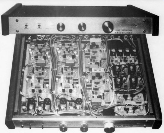
The completed preamplifier is housed in a 17 by 14 by 1.5 inch, 14-gauge steel chassis, fabricated at a local sheet metal shop. A perforated top cover, aluminum front panel and solid African Koa wood side panels complete the chassis. The finish, metallic brown lacquer, oven baked at 200°F for one hour, blends well with the side panels and gold RCA jacks.
In the module layout, from the left side, the first two rows comprise the RIAA-1 and RIAA-2 left and right channel modules, plus associated regulators. The third row comprises the two line amplifiers.
The fourth row is made up of each channel's bipolar pre-regulators, two regulator modules for left and right channel line amplifiers and tape buffers, and left and right channel tape buffers.
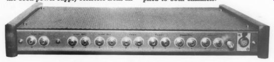
The raw DC supply is housed in a separate chassis, which features separate power transformer, rectifiers and filter capacitors for each channel.
I did not utilize the power supply regulator/distributor scheme which Mr. Borbely outlined in the original article, but adopted a system based on regulators he utilized in "A Moving-Coil Preamp" (TAA 4/86, 1/87).
This system features a separate regulator for the RIAA-1/RIAA-2 modules and the line amplifier/tape buffer modules. Duplicate regulators are used for each channel. The regulators are supplied from a dual bipolar preregulator. The main regulators are those from the moving-coil preamp power supply and include all circuitry surrounding the pass transistors and op amps, that is, all components from C5/C14 to the regulator outputs. I changed the value of R4 and R11 to 3.32k2 to set the regulator outputs to + 22V DC. The LM317/337 preregulator outputs were set to + 27V DC. Therefore, for each channel, one bipolar preregulator feeds two bipolar regulators. I removed the 100 ohm power supply resistors from all modules, except the tape buffers, and then fed the modules with +22V DC from the regulators.
A frequency response curve was generated using an inverse RIAA network and a Neutrik signal generator/plotter, which proved the excellent RIAA accuracy of the preamp.
Module Setup
I tested each module prior to chassis installation, following the setup procedure outlined in the article (TAA 4/86). I also checked all modules with an oscilloscope for output noise and RF oscillations. I monitored current consumption with a Variac during initial module power-up. All modules functioned correctly the first time power was applied, however minor problems occurred with input bias current adjustments on the RIAA-1 and tape buffer modules, which I corrected.
R-1: input stage current was too low as identified by a low-voltage measurement across R4/R14 (2V DC) and consequently output stage current could not be set.
I changed R7 and R8 to 18.2 ohm and the problem was corrected. Voltage drops were within range as specified by the set up procedure and output stage current could now be adjusted. This change applied to both channels.
Tape buffer: Input stage current was too low as identified by a low-voltage measurement across R4/R7 (3.3V) and consequently output stage current was too low.
When R5 and R6 were shorted, voltage drop across R4 and R7 was still too low. I replaced P1 with a 20 ohm trimpot and the voltage across R4 and R7 was then within range, unfortunately the output offset could not be set to zero; it remained at about 15mV DC. To allow offset adjustment, I installed a 4.99 ohm resistor in place of the shorted R5 or R6, depending on polarity of offset when adjusted to minimum. With these changes, the input and output bias currents were correct, and output offset could be adjusted to zero volts DC. This change applied to both channels.
The preamplifier drives a pair of bi amped Snell Type-A loudspeakers, powered by a POOGEd Hafler DH-200 and a home-built, fully regulated, POOGEd DH-200. Sources are a Linn LP-12/Zeta/ Decca Gold and POOGEd Philips CD-104 CD player.
This is a superior sounding preamplifier, characterized by a wide soundstage, excellent depth and detailed top end. My thanks to Mr. Borbely and TAA.
BRIAN SHERK Scarborough, Ontario Canada
Also see:
A Power Supply Regulator For The Adcom GFA-555