Intro; EDITORIAL--The Human Face; Letters; ASK TAA; CLASSIC CIRCUITRY--The Spartan Ensemble; JUST LOOKING
Intro
Why take a chance any longer in your circuit designs on the proper characterization of transistors? Test small signal, reference, rectifier, and zener diodes as well with Contributing Editor Erno Borbely's simple curve tracer adapter. Part I of this two-part article.
This could be a project whose time has come-a build-it-yourself digital level control. What improvements can you expect from replacing the old stand-by potentiometer with an electronic substitute? Read about some of the surprising benefits in William Chater's article .
Andreas Schubert discusses parallel or shunt voltage regulators, un common in electronics though they offer advantages over series or pass regulators for audio applications.
Armed with his figures and formulas, find out how you can set up such a regulator for your preamp.
Simplicity is the name of the game in the circuit developed by Fernando Garcia Viesca to protect your amplifier from your speaker. It is so simple and inexpensive that it can be permanently retrofitted to any amplifier. If you wish to protect your expensive equipment, you'll find this circuit, useful and easy to build.
Editorial
The Human Face
I recently wrote a Speaker Builder editorial remarking on the clear evidence that managers of US companies have become more and more removed from any direct, hands on knowledge of how products are manufactured. The occasion was one conglomerate CEQ's endowment of a chair in manufacturing management at Purdue University with a strong emphasis on familiarity with the worker's eye view of how the product is made.
In response, I had a nice letter from Ken Nelson. It's no secret that Nelson's skill and experience in publishing has contributed considerably to the growth and prosperity of Stereophile, and was Larry Archibald's wise choice for the magazine's advertising sales rep. firm, domestic and international. I quote a part of Ken's letter because he reminds me about a matter often overlooked in the recipe for good audio manufacturing and marketing.
Your editorial concerning manufacturers who ignore 'hands-on' product experience is no doubt true. However, I think you could add a tad about marketing to complete the picture.
"Henry Kloss enjoyed a major asset at KLH and Advent in the presence of guys like Stan Pressman, Fred Goldstein, and others. These were the folks that listened to the sellers and end users who bought the product. They could and did help develop products.
"The ability to put a human face on a brand is as important: it's the extra advantage we all need.
"I can recall the fiasco, when I was first in trade publishing in the 1960s, when American audio manufacturers rushed into transistors and then fell on their collective faces when products failed right out of the box or soon after. It wasn't just failing product but factory policies on returns and service that did the American manufacturers in.
"The Japanese audio producers who were just entering the market made sure their reps would call on stores with inventory in their cars. If there was a problem with equipment, the unit was replaced on the spot, all this with a smile and a 'thank you.'
"Of course, some American brands had such user friendly policies; i.e. Mcintosh.
'So, it's not just product but attitude. Look at the old Harley Davidson. First the Japanese came into the US motorbike market with advanced technology, better products and the market fell to them, ripe and sweet off the American tree.
Harley almost went under, but they fought back with better quality control. They got the product to work right and keep working. They put on a human face and got everybody at the factory to hear what the end user had to say and thought.
Now Harley Davidson is hot. Sales are way up in the US and overseas. Customers are on long waiting lists in Japan. Now the world wants this non-advanced technology motorbike. A product that works, right out of the box." I must agree that the 'human face' has all but disappeared from the audio producers in this country. Part of it is managers and the manager syndrome, all technique and no soul. The product is just stuff. The buyers are just sources of money.
This is not to say there aren't producers out there who care a great deal, but somehow the human face is harder to see. Back in the days when Dynaco was delivering quite wonderful, simple, inexpensive gear, all of us for some reason believed that real people ran the company.
We saw them as practical, hard-headed and clever. I don't remember thinking of Dynaco as competing. They seemed to concentrate so much on plain, well-performing products that they didn't need to worry about marketing tricks or image.
I think we all knew Dynaco was doomed when the Tyco management, who had acquired them, forbid the service people at Dynaco to admit that one of their products performed a lot better with an alternative chip installed. They also nixed offering the chip free to customers for replacement.
We certainly believed that Henry Kloss knew how to manufacture a remarkable amount of performance in small, mass-produced packages. Hermon Hosmer Scott enjoyed enormous respect from audiophiles in his earliest days, and for many years into his remarkable career.
Unfortunately, that kind of statesmanship and human face policy requires a lot more courage these days. To day, that stance also calls for more patience and fortitude because I suspect we, as customers, have become more contentious and demanding, more critical and prone to controversy. We have become cynical about manufacturers, unfortunately all too often with good reason.
I would be glad to hear what readers think of these issues. Are there "human faces” among audio manufacturers which are visible to you, about whom you feel some kind of appreciation and admiration for the kind of job they are doing? Do they listen to you and respond to your needs? Your suggestions? No human enterprise does well without two-way communication. I considered adding a small questionnaire to end this page, but I don't like filling them out and I don't imagine you do either. But if you are moved to write about these issues, I welcome your letters. Better yet, if a company has done well for you, write to them about it-and just send me a copy. One good face deserves another.
-E.T.D.
Ask TAA
By Gary A. Galo Contributing Editor
PREAMP POWER SUPPLY
In Ask TAA, 2/90, I briefly mentioned some excellent three-terminal adjust able voltage regulators from Linear Technology Corp. (LTC). I have used these regulators in power supplies I built for my CD player, and one of my pre amps. The supply design comes from Walt Jung and Rich Markell of LTC. At the time I completed 2/90's column, the supply was being refined, so I didn't include a schematic in that issue.
Walt and I have done quite a bit of experimentation with the supply. Refinements added afterward include separate rectifier bridges for the positive and negative supplies, as well as increasing the output filter capacitor's value to match the input filter. Figure 1 is the schematic of the supply's current version.
A few notes on the supply are necessary. The power transformer should be a hefty toroidal device. Many audio de signers believe any 300mA transformer is adequate for powering preamp circuits. Fine, if you spend most of your time listening to test tones.
Real music's dynamic conditions re quire much more. If you enjoy music with uncompressed dynamics, a wide lateral soundstage, plenty of depth, and precise imaging, a high current, low output impedance supply is a necessity.
No matter how sophisticated your regulator circuit, its performance will be severely limited if you cut corners on the transformer.
I recommend a transformer in the 120VA range, which means 4A for 15 + 15V or 3.3A for 18 + 18V. ILP's 4A013 and 4A014, and Avel-Lindberg's D3021 and D3030 are excellent choices. The dual rectifier approach requires a power transformer with two separate, floating secondary windings. Separate rectifier bridges offer increased current capability for each side of the supply. Only the power transformer now limits interaction between the positive and negative supplies. Features of the LT regulators are: 1) Low dropout voltage, allowing transformers with 15V secondaries to be used in + 15V DC supplies, as long as AC line voltage is 105V or higher; and 2) a 1% output voltage tolerance.
PARTS LIST
R1,3 R2, 4 1k, 1%, ¼ W 10.5k, 1%, 2W C1,3,8 10 4,700 uF/35V Panasonic TSW C2,9 100.F/25V Panasonic C4-7, C11-14 0.01uF, 100V D1-4, D11-14 1N5401 (or 6A, 100 PIV bridge rectifiers) D5-10 1N4002 (100V PIV) U1 LT1085CT (LT1086CT U2 LT1033CT (LT337CD Heatsink, 5W, Aavid 57418 TI-118/18 + 18V, 120VA-Avel-Lindberg D3030
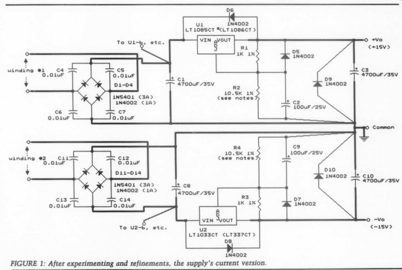
FIGURE 1: After experimenting and refinements, the supply's current version.
Walt would prefer electrostatic shielding between the transformer's primary and secondary windings, reducing high frequency power line noise level transferred to the secondary windings. Find ing a toroidal transformer which has a shield will be extremely difficult, how ever. If you have a power line noise problem, you'll probably have to deal with it ahead of the AC input to your supply.
The discrete rectifier diodes in the schematic may be cumbersome to in stall. I use a pair of encapsulated bridge rectifiers, such as the 6A, 100PIV Digi Key units (#PB61-ND). These contain a hole for chassis mounting with 4-40 hardware. You can also solder the four leads to a PC board. If you chassis mount the rectifier bridges, the shunt capacitors can be easily soldered to the rectifier's leads. The best choice for shunt caps are Panasonic V-Series stacked films. The value isn't critical, anything from 0.01 uF-0.056uF, with a 100V rating, is fine. The 0.01 uF, 100V caps are Digi-Key #P4713.
The 4,700uF, 35V filter caps can be Panasonic TSW series, Digi-Key #P6514.
C2 and C9 can be a Panasonic HF series electrolytic, although low ESR is not critical in this location. Use Digi-Key # P6721. The regulators will need some heatsinking. Aavid's HS-111, 5W clip on cooler is fine, available from Digi Key with the same part number.
For maximum heat transfer, don't just clip them onto the regulators. Use some white thermal compound, and fasten with 4-40 hardware. Diodes D5-D10 aren't necessary for operation of the regulators, but they protect the regulators and the output filter capacitors, in the event of a polarity reversal. I don't consider them optional. Use Digi-Key #1N4002.
A word on regulator choices. Both 1.5A and 3A regulators can be used. Walt recommends optimizing your regulator choices according to the circuitry's cur rent demands. Note the 'CT' suffixes indicate a TO-220 package. No high performance audio regulator should use anything smaller.
Many regulators are available in TO 92 and TO-99 cases, but these are typically low-current devices with unacceptably high-output impedance. The LT 1086CT and LT337CT devices, with ratings of 1.5A, will be fine for most preamplifier and electronic crossover applications. If higher current levels are required, use the LT1085CT and LT 1033CT, each rated at 3A.
If you are pulling enough current from your supply to warrant 3A regulators, the 5W heatsinks mentioned above may be inadequate. In this case, I recommend Aavid type 5812B, available from Allied as part #619-6076. Users should pay attention to the voltage drop across the regulators, i.e. the unregulated DC in put minus the regulated DC output. If this drop is excessive, the regulators will current limit to avoid overheating.
The 15V transformers described above produce in excess of 16V AC on each winding under light load conditions, yielding around 22.5V of raw DC at the outputs of the regulators (rectified DC = AC x 1.414). The voltage drop of approximately 7.5V is fine.
Regulator output voltages (Vy) are adjustable via R1 and R2 in the positive regulator, and their counterparts, R3 and R4 on the negative side. Here's the formula for determining the output voltage:
Vi (the regulator reference voltage) is 1.25V for the LT regulators. R2 will be 8.25k, 10.5k and 12.9k for 12, 15 and 18V, respectively. The Adjust Pin Current (Lg) for most three-terminal regulators is around 50 uA. Exact values LT specifies are 55uA for the LT1086CT and 65uA for the LT337CT. Note R1 and R3 are an order of magnitude higher than the application notes many datasheets show. This allows using higher value capacitors for C2 and C9, and improves ripple rejection.
These regulators require 10mA of cur rent drain before they begin to regulate.
The circuitry will normally provide this, but I prefer to add a resistor across the supply' $ output to ensure a constant, minimum current drain. This also facilitates testing the regulator before the circuitry is connected. If the output is 15V, the bleeder resistor should be {.5k.
The regulator output impedances are actually reduced as heat increases. For best audio performance, a minimum load of 50mA is necessary for the 1.5A regulators. If your circuitry can't provide this (quite unlikely), a lower value shunt resistance can be used to provide necessary idle current. Use R = E / I to deter mine the resistor value, and P = E2 /R to ensure the resistor's correct power rating.
Wiring between the regulator outputs and the load should be as short as possible. I recommend using multiple strands of Neglex hookup wire. Supply by-passing close to the circuitry is important.
Panasonic 470uF, 35V HF series electrolytics, shunted by 1uF stacked film caps is ideal (Digi-Key #P6726 and #P4357, respectively). If regulator voltages reach optimum values more rapidly than you wish, the time can be increased by using larger values for C2 and C9.
Proper component selection is a must to realize this regulator's full potential.
Audio performance will be seriously compromised if you substitute generic LM317 and LM377 regulators. Built as specified, this regulator offers outstanding audio performance. It would take a sophisticated discrete regulator to beat this IC-based design's performance. Try it in your next preamplifier. I don't think you'll be disappointed.
By the time you read this, Linear Technology will have introduced an IC op amp. Preliminary data on the LT1122 shows a 75V/uS slew rate and a 14MHz unity gain bandwidth, yielding an input dynamic range (Vy) of 0.853V. DC off set is low, comparable to the LT1056 devices I discussed in TAA 2/90. Common mode rejection is an outstanding 100dB. I have used pre-production samples of the LT1122-CNS8 in the preamplifier line stage in Fig. 1 TAA 2/90. So far, the LT1122 impresses me as the best sounding IC op amp I've heard for line level applications.
Compared to the LT1056, this new chip has a smoother, more natural high end, with greater inner detail and articulation. Combined with a high performance power supply, such as the one described above, this line level stage pro vides performance equaled by only a handful of expensive commercial pre amps. Even though that schematic indicates + 18V rails, + 15V will perform just as well. Remember, dynamics have little to do with actual rail voltages. It is the power supply's output impedance, and the amplification circuitry which determine dynamics.
Specification sheets on LT's regulators and op amps are available free by calling (800) 637-5545. You might also ask for a copy of the 1990 Applications Handbook, as well as the name of your nearest LTC distributor. Marshall Electronics is an LTC distributor with several locations nationwide. You can ask for the location nearest you when you call.
A kit of parts and a circuit card for the low-dropout Preamp Power Supply will be available soon from Old Colony Sound Lab, PO BOX 243, Peter borough, NH 03458-0243, (603) 924 6371 / 924-6526 / FAX (603) 924 9467. Ask for kit no. KG-5.
----------
ON HOME RECORDING
This issue's questions pertain to home recording. First, reader Harold Barstow of Missoula, MT writes: “What is Dolby's new spectral noise reduction sys tem, and will I be able to use it with my home recording equipment?” A second letter, from Eugene L. Welker of Cornish, NH asks: “I am searching for an affordable two-track mastering recorder for my home studio. What can you see down the road in digital recording for the home recording engineer? I've listened to the Sony PCM-501/Beta VCR combination, but the sound left me cold.
Will modifications be offered for CD ROM, R-DAT, or PCM/Beta digital recorders? Perhaps I would simply be better off finding a way to increase the speed of my old Pioneer RT-1020L to 15ips.” Mr. Barstow and Mr. Welker have asked two related questions regarding recording equipment for the amateur.
Both analog and digital questions need to be addressed. I'll begin with the ana corders are few and far between. The last high quality two-track mastering recorders within the reach of serious amateurs were the Technics RS-1500 series, which had extremely high quality. I own one, and we use four at The Crane School of Music, so I have extensive experience with them.
Featuring a closed loop dual capstan idler system, these recorders offered out standing mechanical performance. The RS-1500 could be purchased mail order for less than $1,100, despite a list price of $1,800. A second version, the RS 1520, was also available, featuring balanced inputs and outputs operating at +4dBm.
Panasonic's professional division marketed a version of this recorder known as the 10A02. In an amazing marketing blunder, the 10A02 was priced too high, and recording engineers soon realized they could buy the consumer version from discount mail order houses for hundreds of dollars less. With no difference in actual performance, they lack accessible bias adjustments. Thus, the 10A02 was discontinued, and Panasonic's Technics division later decided digital audio would render the RS-1500 series obsolete. So, these machines are now history.
Changing the speed on your now classic Pioneer RT-1020L, as on any recorder, is not simply a matter of in creasing the tape speed. The bias and equalization circuits must be modified to accommodate the new speeds, often requiring major modifications to the tape recorder. Your best bet, these days, is to consider two-track models from Teac, Tascam (Teac's pro series), the ReVox PR-99, and the Otari MX-5050 (in order of increasing price).
No Noise, Good Noise
Hardly anyone would consider using an analog recorder without some form of noise reduction, unless you can afford the luxury of recording at 30ips. Noise reduction must be viewed as a necessary evil. A tape noise reduction system
---------------------
which does not impart any imprint on the sound does not exist. Every noise reduction system adds a certain amount of coloration, in my opinion, regardless of how perfectly they measure on the bench. Despite what the pure scientists say, all noise reduction systems emphatically do not sound the same! A survey of professional and consumer noise reduction systems is in order. First, all tape noise reduction systems in wide spread use today are dynamic and complementary. They are dynamic because the amount of signal processing they impart is dependent upon both the energy content and music's signal level at any given moment. They are complementary because they impart one form of signal processing during the record process, and then perform an equal but exactly opposite process during playback. The original signal should be left unaltered by the complementary processes.
Enter the Dolby
First, the various Dolby noise reduction systems. Before the Spectral Recording system, there were three Dolby system versions (3% if you count HX). The first professional version was introduced in 1966. Dolby B is the oldest of the consumer types. During the record process, the Dolby B circuits boost all low-level information above 400Hz. The amount of high frequency boost depends on the signal level, with low-level information above 4kHz receiving a maximum boost of 10dB.
Bear in mind the high-frequency boost takes place before the signal is fed to the tape recorder. The residual hiss inherent in magnetic tape recording is largely from the tape itself. During playback, the decoding circuitry reduces all high frequency information boosted in play back by precisely the same amount. In other words, a 10kHz signal boosted by 10dB during the record process is reduced by 10dB during playback. At the same time, the tape hiss is also reduced by 10dB, but the music returns to its original level. Thus the music remains unaltered, and the noise is reduced by a factor of two.
Dolby C is similar in principle to Dolby B, with two major differences: the high frequency boost begins at 100Hz rather than 400Hz and the maximum boost above 1kHz is 20dB, instead of B's 10dB lift above 4kHz. Dolby C can therefore reduce high-frequency tape hiss by as much as 20dB, reducing noise audibility by a factor of four. The C-type system also uses a technique known as spectral skewing, which reduces the system's sensitivity to extreme high-frequency signals.
The Dolby HX system is compatible with either Dolby B or Dolby C. As we know, low distortion tape recording is impossible without bias, the 100kHz or higher signal applied to the tape along with the audio signal. Bias overcomes the tape's magnetic inertia. However, when the recorded signal contains high frequency energy at high recording levels, a certain amount of self-bias takes place.
The HX system monitors the high frequency energy content of what's being recorded, and adjusts the bias level accordingly. This prevents premature tape saturation, increases headroom, and lowers distortion in the loudest passages.
Unlike Dolby B and C, which do not affect the low frequencies, Dolby A processes the entire audible spectrum. In the record process, Dolby A divides the spectrum into four parts: below 80Hz, 80Hz to 3kHz, 3kHz to 9kHz, and above 9kHz.
The audio signal passes through four filters, similar, in principle, to an electronic crossover. The four are then fed to four separate compressors which boost all low-level information. The lower the signal level, the greater the boost, with the maximum boost 10dB. After processing, the four signals are re-combined and fed to the tape recorder's line input.
During playback, the tape recorder's line output signal is fed back into the Dolby A circuitry. The same filters used in the record process again divide the playback signal, then four expanders re turn all of the information boosted in record to its original level. The four are re-combined and fed to the Dolby A unit's output.
Dolby A was intended for 15ips or higher wide bandwidth recording. The Dolby A units also have balanced XLR inputs and outputs which normally operate at the professional studio level standard of +4dBm. Dolby's B and C systems were intended for slow speed, narrow band recording, including cassettes, and slow speed reel-to-reel. Connecting a Dolby A to a home cassette or reel-to-reel recorder has two problems: first, the home recorder's input and out put levels are too low to allow interfacing with the professional Dolby A units.
Second, even if you adjust a Dolby A's input and output levels to match (they're adjustable over a fairly wide range), high-frequency mistracking will occur. In order for dynamic, complementary noise reduction units to track properly in playback, all the information processed during record must be return ed to the noise reduction units during playback. If Dolby A units are used with recorders having a high frequency roll off, they will mistrack in playback.
All three Dolby noise reduction systems are level sensitive, meaning record and playback levels must be matched.
When external Dolby units are used with a tape recorder, a Dolby test tone is recorded on the tape at 0-VU. When the tape is played back, a level control on the Dolby unit, or the tape recorder, is adjusted until the Dolby unit's meter reads “0. ” All Dolby As are external, and very expensive. A stereo pair will cost well over $2,000. When home reel to-reel recording was popular, several external Dolby B processors (and even one or two C-type units) were available. To day, nearly all cassette decks contain internal Dolby B and C processors, pre venting level matching. If your cassette recorder is properly aligned for the tape you are using, it is also unnecessary.
Spectral Purity The Dolby Spectral Recording (SR) sys tem was designed to improve sound re production purity by applying the principle of least treatment. In other words, the audio signal's processing amount is minimized by concentrating the processing on only those portions of the audible spectrum where it is needed.
Dolby Labs publishes the eight-page pamphlet Dolby Spectral Recording- What It Is and What It Does, as well as a reprint of Ray Dolby's lengthy AES paper The Spectral Recording Process.
Both are available from Dolby Labs, 100 Potrero Ave., San Francisco, CA 94103 4813, (415) 558-0200.
Dolby's Spectral system consists of 10 fixed-band and 10 sliding-band filters.
Those with fixed bandwidth are capable of varying their gain, while those with fixed gain are parametric, in a sense, since they can vary the frequency ranges they cover. Dolby SR units can create an infinite number of filters for the signal before it is recorded. During the play back process, filters are dynamically created which are the exact opposite.
The SR system filters continually adjust to maintain the highest possible gain at all frequencies as the energy content (i.e. the frequency spectrum) changes.
SR is a professional system, intended for fast speed, wide bandwidth tape recorders. In a November 1989 press release, Dolby Labs announced an adaptation of their Spectral process for slow speed cassette recording, known as Dolby S-type. According to the release, "When incorporated in a high quality machine using today's best tape formulations, Dolby S-type provides analog cassette performance subjectively equivalent to digital media under home listening conditions." Only time will tell whether the system can live up to the claim. If outboard S-type units ever become available they could be extremely useful to the home reel-to-reel recordist.
Competition From dbx Dolby's leading competitor in the professional and home recording markets has been dbx. Like Dolby, dbx systems are dynamic and complementary. Un like Dolby B and C, dbx units operate over the entire audible spectrum. During record, all low-level information is boosted, the maximum being 30dB.
During playback, all boosted information is expanded downward, again by as much as 30dB.
This reduces tape hiss by 30dB as well.
dbx uses true RMS level detection circuitry, allowing the compressing amplifier (record) and expanding amplifier (playback) to accurately determine the input signal level. The expansion amplifier gain changes are, therefore, accurately mirrored in the compressor processing.
dbx also applies a fixed treble pre emphasis in record, prior to the level detection and compression. During play back, a complementary de-emphasis is applied, after the level detection and expansion. Pre-emphasis and de-emphasis reduces asperity noise and modulation distortion by 12dB. There are two dbx systems, Type I and Type II. The differences lie, in part, in how pre-emphasis and de-emphasis is accomplished.
dbx I noise reduction carries pre-emphasis and the RMS level detection sen sitivity up to 20kHz, while dbx II noise reduction rolls off the pre-emphasis above 10kHz, and the RMS level detec tors are only sensitive up to 10kHz. You can probably guess the reasons for the two systems. dbx I was developed, like Dolby A and SR, for high speed, wide ire quency response, and dbx II for slow speed recorders with reduced high frequency response.
If a dbx I is used on a cassette recorder or slow speed reel-to-reel, information loss above 10kHz by the tape and the recorder causes mistracking in playback.
Mistracking sounds like the low-level dynamics are being artificially pumped, with the background noise level rising and falling with changes in dynamics.
Noise reduction mistracking is very offensive and must be avoided.
dbx noise reduction systems are not level sensitive, and do not require test tones and level matching. They are extremely sensitive to tape recorder equalization, however, and your tape recorders' record and playback electronics must be properly aligned before using either system. dbx I is even more sensitive to recorder alignment errors than dbx II.
Drum Rolls, Please
Which systems do I prefer? I have extensive reel-to-reel recording experience with Dolby A and dbx I noise reduction.
I use Dolby type A at most live concerts, re cording at 15ips. dbx adds a slight harsh ness to high frequencies, particularly noticeable on high strings and massed choral sopranos. Dolby A is smoother in the high end, resulting in a slight clarity loss and veiling the music. I do use dbx I for two types of music.
We have an outstanding percussion ensemble at Crane. The extraordinarily wide dynamic range of percussion music (everything from a triangle's playing pianissimo to 20 players beating the daylights out of every instrument on stage) is well served by dbx I's 20dB improvement over Dolby A in signal-to noise ratio. The harshness dbx imparts to strings and choral sopranos is not a problem for percussion, nor for contemporary music groups, whose dynamic range is often nearly as wide. Instrumental scoring, also is not bothered by dbx's harsh top end.
If recording 7.5ips on reel-to-reel, (until Dolby's S-type is available in out board units) your best choice is dbx II.
I do some dbx I recording at 7.5ips, but I keep close tabs on tape recorder alignment to prevent mistracking. Below 15ips, dbx I is too risky for the average home recordist. dbx II is used in many cassette decks, but I don't recommend it under any circumstances. At 1 7/8 ips, even DBX II is prone to alignment errors.
Your dbx-encoded cassette may play back without problems on the unit you used to make the recording, but mis tracking is highly likely when playing the tape on another dbx-equipped cassette deck. Nakamichi, in my opinion makes the finest cassette decks in the world, but doesn't include dbx noise reduction. I believe your best bet for cassettes is Dolby B, C, or the S-type system, when it's available.
DAT's the Future
Getting back to Mr. Welker's question, I believe DAT is the wave of the future for high performance home recording. I have been recording digitally at Crane since late 1984. The recorder we purchased was a Nakamichi DMP-100 (their version of the Sony PCM-F1), along with a Sony SL-2000 portable Beta for storage. I never liked the PCM/Beta combination's sound either. Compared to analog, the digital recordings have a harsh high end, and the hall ambience is noticeably truncated, making the recordings sound dry. Soundstage width is narrow and depth perspective is on the short side-all of this using the same microphone feed.
People who told me the PCM-F1 recorder was perfect, and that my ears needed re-adjustment frustrate me. One engineer told me the wow and flutter in all analog recorders possibly added pseudo-ambience to my analog recordings, and that the PCM-F1 was more ac curate. I didn't buy it.
I made several comparisons, on-location during live recordings, of the direct headphone feed from my mixing con sole, and the DMP-100 recorder's head phone jack. Bear in mind when you listen to the DMP-100”s headphone jack, you are hearing the digitally-processed signal. Every person who heard the com parison said the digital recorder's output had less hall ambience and more clarity than the direct feed from the mixing console.
All that has changed. Today's best digital recorders are free of the problems which plagued their “perfect” predecessors. I've made about 25 concert recordings on a recently purchased Panasonic SV-3500 professional DAT recorder. It is superior in every respect to the PCM/ Beta combination. The high end is much smoother (though not perfect), soundstage is wide and incredibly deep, and hall ambience retrieval is equal or superior to my analog recorders.
Improving the Op Amps Can the SV-3500 be improved? Absolutely. The Japanese manufacturers have a fetish for the sonically-dated 5532 op amp, a decent dual op amp circa 1980, but its sonic performance is mediocre by today's standards. Yet, the Japanese (and others) stick the 5532s into many products. Nakamichi, who should know better, even uses them in their $11,000 DAT recorder. Several CD players claiming high-end performance also use them.
The SV-3500 uses many 5532s in the analog circuitry. After my warranty expires I'm replacing them with Analog Devices' AD-712, the best sounding dual op amp I have used, a change which should improve sound in the high frequencies.
SV-3500's positive attributes are, in large part, due to A/D and D/A converters which have good low-level linearity. We now know the PCM-F1 had serious low-level linearity problems, contributing to the lack of hall ambience. Costing around $2,500, the SV 3500 is out of the reach of many home recordists. Low-cost consumer DAT recorders, however, are on the horizon.
DAT”s only disadvantage is lack of editing capability. Professional digital editors for DAT recorders are available, but, again, the prices are very high.
If You're Buying...
I recommend getting to know a dealer specializing in professional and semi-pro recording gear, one who can supply you with current model numbers, prices, and product literature. One such dealer is Boynton Studio, Inc., Melody Pines Farm, Morris, NY 13808, (607) 263 5695.
Boynton is an authorized dealer for all manufacturers listed above, including Tascam, ReVox, Otari, Dolby, dbx and Panasonic. If you are interested in the Teac home reel-to-reel recorders, con tact International Electronics World, 6330 Frankford Ave., Baltimore, MD 21206, (800) 638-3920 or (301) 488-9600.
If you move and do not send us your new ad dress in advance, your current-issue is sent to yo ur old address and may arrive after the postal Service's six-month time limit on for warding instructions has expired. If this hap pens, the Postal Service sends us a notice saying, in effect, they have forgotten where you now live, along with a bill he 30¢ to pay for this iniamation. Meanwhile, they have trashed your magazine.
Since we have already paid for your destroyed copy, paid postage to attempt to deliver it to you and put a holding code in your computer record sac - o- we have no idea where you are, and er since we routinely act on the assumption that Murphy is over active within most offices of the Postal Ser vice, we send a first-class letter to your old ad dress to determine whether you have, in fact, moved. We do this because from time to time some clerk mistakenly supposes a subscriber has moved and he or she has not. Then we write a - letter to the Postmaster suggesting the clerk is a vandal of sorts and how about paying for the magazine? So far, not one has sent any postage or even a repentant let ter. SH. usually range from form to frown Popieencil lease inform us early when you move.
Peel off your label, put it on a postcard, write in your new address and send it to us. We can not afford to send you a duplicate, unfortunately. If your copy becomes a Postal Ser vice casualty, the replacement copy will cost $5.
LETTERS
CD MOD FIX--AGAIN DUE TO OUR oversight, an inappropriate letter by reader Ira Wilner was published in TAA 3/90, p. 55. The letter was the early one of a pair concerning POOGE techniques in general, and questions about the Jung/Childress CD modification articles in TAA 1, 2/88. The letter published was sent to the authors and they replied to Mr. Wilner, clearing up his questions. Mr. Wilner then sent a second letter to them, reporting a new problem. A portion of this second letter, for which Jung's reply is appropriate, follows:
"Over a year ago I purchased a POOGE-4 kit from Old Colony but only recently got around to installing it....
Using it with Spica TC-60s and Stax Lambda Professional headphones...I listened to both my POOGE'd player and one with just the AD-712 upgrade. The sonic detail seemed better on the POOGE'd machine but the overall impact, especially...low-frequency material, sound stage and depth seemed about the same or a smidgeon less. So I was not convinced it was worth the extra cost and complexity. I brought the machine to the public radio station so my “golden eared” colleague could appraise it too.
"Driving the medium/low impedance bridging load of a McCurdy broadcast console, (6k) it had a decidedly diminished low-end response when compared with any other Philips machine. The transient definition seemed good but the overall low end was unacceptable .... I determined to find what was wrong.
[After a long search I discovered that] apparently the input of the auxiliary out put amplifier was loading down the out put of the MA board. The CDB-650 schematic shows that the auxiliary amplifier, audio filter board, is driven directly from the output of the main amplifier.
"Its input is a low-pass filter. The first pole consists of a 91 0-ohm resistor loaded by a 6nF capacitor. Since the output of the MA board is directly connected to this capacitive load through only 910 ohm of isolation, it is heavily loaded at high frequencies. The original audio op amps had lower source impedances due to active auxiliary amplifier. When I removed the 10 0-ohm resistor protecting the video buffer output on the MA board, it lowered the MA board's source impedance enough to mostly mitigate the loading effect of the auxiliary amplifier's input...."
"I chose to remove the 10 0-ohm video buffer output resistors and adjust the third pole filter capacitor value to trim out the remaining response error caused in part by the loading from the filter board and component tolerance in the main LPF. I also chose to substantially increase the output coupling capacitance because I gained low-frequency extension.” Walter Jung's reply, printed on page 55 of 3/90 addresses the problem Mr. Wilner's research uncovered. We regret any confusion which our error may have caused. -Ed.
Walt Jung adds:
The letter exchange between Ira Wilner and Walt Jung/Hampton Childress published in the “Letters” column of TAA 3/90 may have caused some confusion to POOGE-4 fans either having these modifications or considering them. Our response in that issue, page 55, was written to ad dress the sole technical point Mr. Wilner raised which is based on actual sub stance, that is the loading of the 'additionally filtered' board (in the 650 only).
We addressed this specific issue as we did with a response intended to stand by itself, because the letter from Mr. Wilner we had been given to understand was not for publication.
We would like to also note here that we do definitely take exception to any inferences that the output coupling ca pacitor/load resistor of the POOGE-4 design is inadequate, when used as originally described. Readers should note that the original output coupling time constant was 220uF, 4700 ohm, or 1 second.
The replacement POOGE-4 values are 10uF 100k, which also yields 1 second.
Only in cases where the external (preamp) load resistance is appreciably less will higher capacitance be necessary. A loading input impedance of 50k will not be critical in this regard, as the net loading of 100k in parallel with 50k is still a time constant of one-third second, corresponding to a low frequency cutoff of 0.5Hz. Net load impedances of below 10k were really not the goal of the design, but they may justify a high quality electrolytic, such as a Panasonic “H F” unit (just as suggested as an alter native within the original POOGE-4 article [1/88, p. 10]).
WALT JUNG AND HAMPTON CHILDRESS
PO Box 36141 Towson, MD 21286-6141
CORRECTION
MY CABLE TESTER described in Audio Aids (AA 2/90) contained a couple of errors which crept into the text during editing which might confuse those constructing the device.
1. Page 59, column 3, lines 6-8 reading 'Once assembled, connect the batteries and switches S; and S, to either the GROUND or POS position." It should read, “Once assembled, connect the batteries and switch S; and S, to either the GROUND or POS position.”
2. Page 59, column 3, the sentence starting on line 15 below “Parts List' and ending on page 60 should read 'If the cable is good, the two LEDs will light up brightly in both switch direc tions, even when the cable is wiggled vigorously along its entire length (most problems seem to be associated with the plugs themselves. ” The text describes two green and two red LEDs, while in fact there is only one of each color.
S. WAYNE Cox
SHORTLY AFTER MY Audio Aid (TAA, 3/88) on building an antenna switch box appeared, a reader commented on the design's unsuitability for FM, suggesting better results by purchasing a Radio Shack switch box. Experience with my design has been very satisfactory in performance and reliability. The reader's comments, however, prompted me to perform rudimentary design tests. This design came about because of the poor performance and short life from a Radio Shack antenna switch box.
The reader said that, because the change from 75 ohm coax cable to bare wire inside the chassis is an abrupt impedance step, it causes reflections which, in turn, can cause ghosts in TV and multipath in FM. Actually, the box's internal wiring is 16-gauge stranded wire which is insulated, rather than bare.
There may well be an abrupt impedance change, but I think the operative word is “can” change, because performance has been very good. We are talking about 2-3” per internal wire inside a closed aluminum box, with coax bulk head connectors transferring the signal from coax to box. Measured signal strengths from signal sources are no different with the box in the circuit, than with it by-passed by physically removing it. I used the signal strength meter on the tuner and a VOM to check and compare.
The reader also pointed out isolation between the two inputs is inadequate, so one antenna signal will leak to the other. Disconnecting one signal source and then the other, while checking signal strength in both switch positions, I identified low-level internal crosstalk.
I removed this with a minor modification. I wrapped the box's internal wires with a single layer of aluminum foil.
This was simple and effective. I believe the aluminum box is effective in shielding internal wiring from external influences. The foil wraps appear to have eliminated internal crosstalk.
I bought one of the newer Radio Shack switch boxes which the reader recommended (Catalog Number 15-1249).
After comparing its performance to my design, they appear equal in performance, in the sound, measured signal strength through them, and isolation be tween signal sources. Three years of use have proven the reliability of my switch box.
JAMES T. FRANE Orinda, CA 94563
YIELDING SHIELDING
I WOULD LIKE TO respond to Ron Sawyer's comments in Audio Aids (TAA 2/90. For shielding unsymmetrical audio cables, it is better to reverse the screen attachment point. This is contradictory to the information supplied by Mr. Sawyer (Fig. 1).
CABLE - BELDEN 8451 (RCA PHONO PLUG) CONNECT AT THIS END ONLY
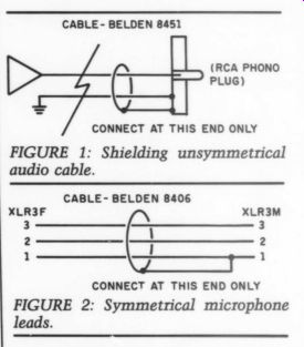
FIGURE 1: Shielding unsymmetrical audio cable.
FIGURE 2: Symmetrical microphone leads.
In the application of symmetrical microphone leads, the cable should be connected as illustrated in Fig. 2. This has been the standard of the old WESTREX wiring scheme for many years, and is still in use in several broadcast houses.
This wiring scheme's logic, as explained to me years ago, is that the screen should not carry any ground cur rents. It should only act as a drain. This explains the need for a two-core screened cable for unsymmetrical cables, and a three-core screened cable for symmetrical cables.
STEVE ALHART; Boonton, NJ 07005
Ron Sawyer replies:
Mr. Alhart's suggestion that the shield return connection be made at the phono plug end of the cable is probably based on a rule-of-thumb that goes something like this: '"When connecting a shielded cable between two pieces of equipment, the shield return connection should be made on the equipment where the signal level is higher." This rule is valid as stated, for the following reason: The shield will not be 100% effective, and a given amount of noise leaked into the input of the final power amplifier will be less audible than the same amount of noise leaked into the input of a preamplifier stage.
With a WESTREX type of system employing three-conductor connectors, we are free to ground the shield at either, or both ends. Making do with a two conductor connector, as I proposed in my Audio Aid, imposes some limitations on the shield ground connection.
I have drawn Fig. 1 to represent the "front end” of a home audio system.
The signal generator (A) is a low-output moving-coil type phono cartridge. Any shielding (B) applied to the cartridge or connecting wires is grounded directly to the turntable motorboard C), which is, in turn, connected to the pre-preamp chassis (F) by a ground wire (D). The output of the cartridge is taken to the in put of a gain-of-10 “head-amp” (A1) by means of a coaxial cable (E).
A source of noise (G), which may be 60Hz hum or some form of radio-frequency-interference (RFI), is coupled in to the signal conductor via stray capacitance (C1). The noise currents travel in the loop. That portion of the noise appearing in the signal conductor between points and ( is mixed in with the output from the cartridge and amplified by Al. A similar noise loop associated with stray capacitance (C2) is seen at the input of the RIAA equalizer amp (A2).
Figure 2 illustrates the situation when ...
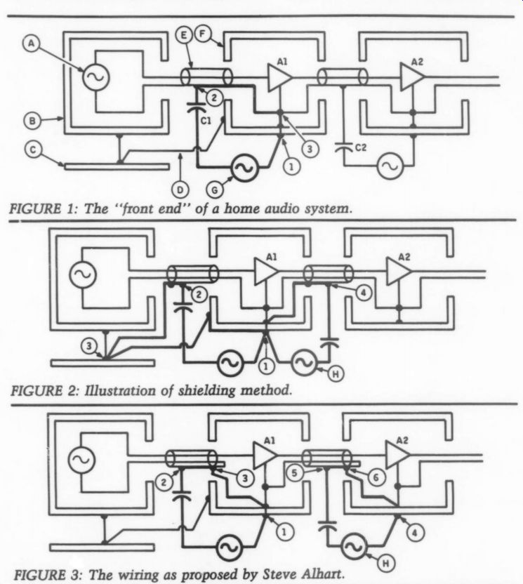
FIGURE 3: The wiring as proposed by Steve Alhart.
... the shielding method proposed in my Audio Aid is employed. The cable be tween turntable and head-amp is permanently affixed to the turntable, and the outer shield is returned to ground at the turntable motorboard. The noise current path is now confined to the shield conductor loop 1-2-3-1 . This loop is isolated from the wires carrying the audio signal. We have thus constructed an effective shield. A similar cable hookup between Al and A2 results in a shield loop 1-4-1 and again the signal conductors are effectively isolated from the noise.
Figure 3 illustrates the wiring pro posed by Mr. Alhart. Note point 6 on the cable connecting Al and A2. This represents the point on the outer conductor of the male phono plug where the negative signal wire and the shield are tied together. At this point, isolation be tween signal and shield noise is lost; both signal currents and noise currents from noise source (H) travel in the conductor between points 6 and 4 , and are amplified by A2.
This is the same problem we found in Fig. 1, which makes this approach less desirable, in my view, than the technique illustrated in Fig. 2, and my Audio Aid. It was offered as a method of im proving cable shielding while working within the constraints of the industry standard "RCA” connector and cable system.
I believe it can be safely applied to the output of any turntable, preamplifier, CD player, or tape recorder. The perfectionist, with less concern for compatibility or resale values, may wish to replace his RCA type connectors with true three-pin connectors of the XLR or DIN variety.
CORRECTIONS
IN OUR 4/89 issue, there is an error in the parts list for 'A Power Supply Regulator for the Adcom GFA-555." Q1, 2, 9 should be 25C2240, and Q3, 7, 8 should be 2SA970. They are shown switched on page 37 of 4/89 issue. The schematic and stuffing guide are OK-only the parts list is in error. This switch will cause the 1k resistors to burn out but should not damage the transistors-just switch them back to the way they should be and it should work OK.
KiT RYAN Annapolis, MD 21403
SOLVE THIS PUZZLE
BILL CHATER'S REMARKS on the audible differences between “good” and 'not so good” preamps which defy measurements (TAA 2/90) once again give me that King of Siam feeling-a great puzzlement. The effect of crosstalk on imaging Bill mentioned in his tests, and the auditioning panel's report, is highly controversial.
If the preamp is auditioned via loud speakers, and in a listening room, these criteria are notoriously unreliable for subjective comparisons. Moving your head a foot drastically changes the image, even to the limits of balance and filter controls. I recommend electro static headphones, the equivalent of an audio magnifying glass, for close subjective comparisons.
I am currently testing a preamp, and the opportunity arose to compare cross talk effect at -45dB and -60dB by shunting an additional resistor in the balance circuit. This was easily detectable by listening to the “quiet” channel with the main channel disconnected from the headphones. With both channels working, the difference was inaudible on any kind of source material, from transient click signals to chamber music, master tapes, or CDs.
Increasing crosstalk to -20dB, it was just possible to detect sound stage narrowing on some material, but this be came unreliable upon retuning to the loudspeakers in my listening room.
There was no effect on “depth,” as this aspect of the audio illusion depends largely on the direct/reverberant ratio of sound the microphones pick up. You have only to concentrate on “depth” in mono to realize how little stereo adds.
Away from the workbench, and out into the world of imperfect recordings and even worse transducers, beset by domestic opposition from fridges, freezers, fans, and the dog next door, one wonders if a Walkman would be a better bet.
ALAN WATLING; Colchester, England CO4 3JD
William Chater replies:
Mr. Watling has me wrong. I think. I didn't say the differences between pre amps defied measurements. Quite the other way. I claimed to see something in the measurements which might (but might not) be reflected in the way the unit sounded. The listening panel pursued this in their own way, eventually believing there was an improvement.
This experience seems to be one of those controversial issues: if a piece of equipment sounds right, but by measurement seems to have some quirk, then is it more desirable to have good measurements but less than desirable sound! I am reminded of a friend who taught me woodworking. He claimed a piece of wood was cut right if it looked right, even if it measured wrong. And if it measured right but looked wrong, it was wrong.
I understand how aptly this applies to audio equipment designers.
RKV CAR AMP REDUX
ALTHOUGH I DIDN'T build Randolph Vikan's car amp (TAA 4/88, “RKV Car Amp', p. 7) I enjoyed the article and readers' letters. It was refreshing to see an objective view of the automotive stereo scene.
I would like to request a schematic and parts list for a negative voltage power supply (again automotive usage) to power op amp active filter circuits, equalizers, crossovers, etc. Since noise, size, heat, and complexity are such problems, I felt it far wiser to ask advice. I suppose noise is the chief problem, al though complexity and sufficient amperage to supply several filters is also of concern.
If you could help, I would be grateful.
Since you are an automotive expert, a negative opamp power supply is probably old hat to you. Certainly many Audio Amateur readers might be interested in doodling with custom auto motive parametric equalizers or active Crossovers.
EDWARD ENDICOTT; San Francisco, CA 94122
Randy Vikan replies:
Thank you for your kind words about my article. Obviously, my power sup ply PC board can be used as a negative voltage automotive supply, since it has both negative and positive rails. By adding a LM337 minus regulator at the out put of my -33V DC rail any negative voltage between -30V DC to -1.25V DC can be obtained.
This only adds to the supply's complexity, something which you seem to ...
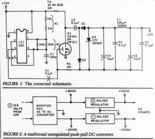
FIGURE 1: The corrected schematic.
FIGURE 2: A traditional unregulated push-pull DC converter.
... wish to avoid. The simplest dedicated negative supply I'm familiar with is the charge pump circuit (TAA 2/89, p. 51).
The corrected schematic is Fig. 1.
The 555 is set up as a 100kHz astable multivibrator, whose output controls the MOSFET power switch. When the MOSFET device is off, capacitor C3 is charged to the positive supply. When the power switches on, C3 delivers a negative voltage through the series diode D1 to the output. The zener diode D3 serves as a shunt regulator. An LC pi network (C4-7 and L1) is added to the output to filter switching noise. This circuit's main advantage is that a trans former is not needed. Its disadvantage is its limited current capacity.
If you need more current capacity, a simplified version of my supply can be used to feed current to a high quality bipolar regulator, such as the Sulzer circuit, (TAA 1/83, p. 18) or Borbely's MC preamp power supply, (TAA, 1/87, p. 37) or Didden's wideband power supply, (TAA 1/87, p. 22).
Since the add-on regulator will per form the regulation function, the regulator circuitry on my DC-to-DC converter can be deleted. The supply tiering and protection networks will also be unnecessary. Refer to the parts list for RKYV car amp power supply, (TAA 4/88, p.- 9).
Delete resistors R2, 14-16, 19-21, and 23. Delete diodes D6-9. Delete capacitors C9, 12, 15 and 16. Delete devices IC2, Opto1, Opto2, Q5 and Q6. Delete T1's tertiary turns. Change T1's secondary turns from 11 to 9.
Adjust secondary turns to fit your requirements using the formula:
These changes convert my supply into a traditional unregulated push-pull DC converter. Since the supply will only be called on to deliver current to line level op amps, and not a high-powered out put stage, the switching MOSFETs' and rectifier diodes' sizes can also be reduced. Remove R1, 8, Q1 and 4. Change D2-5 to MURB820 or equivalent (Fig. 2).
I hope all these possible changes don't confuse anyone. Automotive audio circuitry can be powered in a number of ways, all perfectly satisfactory. I'm sure other people have different ideas. I've built a number of projects from TAA articles, but I've never copied one exactly as written. I've always modified them in some way to fit my needs. I hope I have given you some ideas to tweak my project to fit your needs.
AN ITEM OF CONCERN
WITH FOND MEMORIES, I read Mr. Poehland's article about the SWTP Tigersaurus amplifier (TAA, 1/90). It was a good amp, after I fixed up the problems I had caused in assembly. I currently use a Tiger .01 for subwoofing, and with good results.
One item of concern I would like to pass on to readers: Mr. Poehland suggests using acetone for cleaning PC boards. That might be OK if there are no plastic components. Some plastics, however, will disintegrate faster than butter melts on a hot skillet when ex posed to acetone.
Another solution used in the industry, also compatible with plastics used in electronics is tri-chlorethane. It is avail. inlarge quantaties thru chemical supply houses, or in hobby-quantities at hardware stores. It will probably be in the department with acetone, denatured alcohols, etc. While the container may have some brand name, look at the con tents for tri-chlorethane.
PAUL BECKER, Spokane, WA 99205
POOGE-ing A HEATH AR1500
READER GERALD BURT provided a letter in TAA 3/89 (p. 60) querying the relative merits of POOGE-ing a Heath AR1500.
My own experiences with a similar vintage Heath product may be helpful.
About three years ago (after a William son 40-40 proved audibly superior) I modified my AA1506 basic power amp.
After capacitor changes made little sonic difference, I modified the output stage to a complementary configuration (all of the Heath amps and receivers of this vintage are quasi-complementary). This change provided marked sonic improvement and I believe the amp is fully up to modern standards.
The conversion to full complementary outputs was tricky because the out put transistor sockets on most Heath amps are soldered to the board, and the driver configuration is not symmetrical.
To make the mod easier, I replaced both drivers and outputs with Darlington out puts (NPN 2N6284 and PNP 2N6287).
The reduced parts count makes it possible to modify the signal paths using jumpers on the existing board. You should remove the socket for the PNP output and solder jumpers to the pins used.
I have had several Heath audio products over the years (AR29 and AR1214 as well as the AA1506) and always appreciated the quality of controls and components used. I would encourage Gerald Burt to keep the AR1500 and improve it. In the amp section the outputs should be the most significant improvement.
GLENN WALLBERG, Baltimore, MD 21211
VARIABLE FREQUENCY
I READ ROBERT BODMER'S article on a variable frequency power source for AC synchronous motors (TAA 4/88) with interest. As Bodmer points out, the concept has been incorporated in several commercial audio products. My familiarity with industrial variable frequency drives has made me aware of a point of caution which I would like to share with the readers.
Industrial variable frequency drives use one of several methods of synthesizing a crude sine wave and take advantage of the inherent motor inductance to help filter out harmonics. Such system designs are optimized for maximum efficiency, with spectral purity only important to the extent that the output waveform not cause excessive stress on winding insulation or heat due to eddy current losses in the iron core. The latter problem is one of the reasons it is costly to make audio power output trans formers with good high frequency characteristics.
To compensate for lower reactance of motors at lower than 60Hz design frequency, industrial drives reduce motor voltage with reduced speed (frequency).
In this way, the motor operates at constant torque and variable power output.
However, when operating the motor at higher than 60Hz design frequency, the voltage is held constant, even though motor reactance increases with in creased speed (frequency). In this case the motor operates at constant power output, while the torque decreases.
Ideally, we would just merrily continue to increase the voltage to the motor as the frequency and reactance in creases, without any loss of torque. But at some point reality beckons and insists that we not raise the voltage beyond what the windings were insulated for and that we not try to extract more power from the motor than for which it can safely dissipate the heat generated from its various internal losses.
Readers should thus resist any temptation to increase voltage to the motor significantly beyond its rated 110V, even though this may cause problems due to marginal or inadequate torque at 45 rpm. While a more powerful amplifier may indeed be able to force the motor to produce abundant torque at higher speeds, there is some risk that such operation may damage the motor. Also, should there be damage due to such operation, the manufacturer would be within his rights to void your warranty.
My recommendation for 45 rpm operation is to bear the inconvenience of a pulley change for those turntables so equipped and use the variable frequency power source only for precise speed control. For those with single-speed turn tables who must operate at higher than 60Hz, follow Mr. Bodmer's startup ad vice, and keep a vigilant eye on the motor voltage. You also should find this device usable on any standard induction motor-driven turntable (within power limitations, of course). While induction motors will not yield the crystal-locked speed accuracy obtainable with synchronous motors, their speed is predominantly determined by the line frequency as well, and thus, they are easily controlled in the same way.
RAYMOND KILMANAS, Trenton, MI 48183
Robert Bodmer replies:
I appreciate your remarks and your points are well taken. I do take exception to your comments about operating motors above their nameplate speed.
The motor in the Linn turntable rotates at 300 rpm in the 33.333 rpm speed and at 405 rpm in the 45 rpm speed. I don't consider this a serious overspeed as many motors of similar size turn considerably faster. The overvoltage is a result of ripple in the three-pole filter.
My power supply puts out 140V in the 45 rpm position and 110V at 33.3 rpm.
I have had no problem with the voltage.
Note the output is very clean with regard to line transients which can exceed 1,000V on the normal power line.
Of course, the voltage can be turned down; starting at 60Hz and switching to 81Hz should give reliable starts.
I encourage you to experiment. I have a collection of small motors to experiment with in tape decks, turntables, and just for fun. I have broken some, but never burned one with variable frequency or minor overvoltage. Needless to say, if you are nervous about the experiment, you shouldn't proceed.
WORD TO THE WISE
SINCE PHILIPS/MAGNAVOX discontinued the CDB-582, many audiophiles (myself included) have started using the new Philips CD-50 as the base for their various modifications, such as POOGE, among others. In my opinion, the CD-50 is an extremely nice unit to work on, for the following reasons:
1. The transport doesn't need to be removed to get at the board.
2. The board doesn't need to be re moved from the player to get at the underside.
3. As Bart Simpson would say, 'It looks WAY cooler, man!'
However, the reason I'm writing this letter is to warn all prospective CD-50 modifiers that Philips has swapped the two amplifier sections of the NE-5532/LM-833s, as referenced to the CDB-582 and CDB-650. In other words, while the earlier units had the output of the DAC feeding the first section of the op amp (pins 1, 2 and 3), with the second half (pins 5, 6 and 7) acted as the output buffer, the CD-50 has the two sections reversed. This means that if you are building the POOGE op amp modules detailed in “Direct Mods For The Magnavox CDB-650,” by Kenneth Beers in TAA 1/89, you need to switch the positions of the NE-530 and the LH-0002 (and their respective resistor networks) on the eight-pin DIP header, paying close attention to the proper in puts and outputs, and their pins on the header. Failure to do so will result in the LH-0002 working as the filter section, and the NE-530 working as the output buffer-not exactly the way God and Walt intended. It goes without saying that the various wires on the header going from pin-to-pin need to be changed as well, so make sure you pay attention to what you're doing while you make up the modules for the CD-50. A message to Kenneth Beers: How about a new build-it article for the CD-50 style modules, with new drawings? I'd do it, but I can draw about as well as I can dance.
Good luck to anyone working on these players, and I hope my “discovery” helps you avoid building up the modules only to have to redo them.
COREY GREENBERG, Austin, TX 78759
Just Looking
Analog Devices, Inc. has developed a dual 18-bit digital-to-analog converter (DAC) designed specifically for high-performance, multi-channel digital audio applications, such as electronic musical instruments, CD players, digital mixing/editing systems, and multimedia workstations. Measured according to EIA] standards, the AD1864 guarantees minimum 110dB channel separation and maximum 0.0025% (0dB) total harmonic distortion + noise (THD +N). Signal-to- noise ratio is typically 108dB.
The AD1864 operates from +5 to + 12V supplies, typically dissipates less than 25mW of power, and easily inter faces to popular digital filters. The IC is packaged in a 24-pin DIP, and requires no external components to achieve its rated performance.
This complete monolithic converter can improve performance and reduce external circuitry. Compared to similar devices, the AD1864 dissipates just one half the power, while its minimum channel separation is 14dB greater. The IC can be applied 10 designs requiring two tight ly matched DACs, and eliminates the circuitry required to de-multiplex a single converter design. In such applications, the AD1864 is a less expensive and space saving solution.
Fabricated on a high-density BiMOS process, the AD1864's deign integrates CMOS logic elements, both MOS and bipolar linear elements, and laser-trim med thin-film resistor networks. Fast CMOS logic elements comprise the digital input port, on-board digital registors, and the internal decoding circuitry.
Each independently controlled channel of the DAC is equipped with a short circuit protected amplifier, which pro vides a +3V (peak) output signal. The AD1864 may also be operated in current mode, providing a + mA (peak) output signal. In current mode, an internal feed back resistor is provided for optional use with external amplifiers.
Contact Analog Devices, Inc., 181 Ballardvale St., Wilmington, MA 01887, (617) 937-1428.
Olsson Engineering has announced the Automated Active Filter Design Kit. The kit consists of a circuit board and an active filter design program, which has been optimized for the variable circuit configuration. The circuit board implements six general purpose second-order filter stages, and can support all common circuit configurations (low-pass, high pass, band-pass, band-stop, and all-pass).
The kit provides the user with fast turnaround time for custom filter con figurations. Most common filter types are supplied in the filter parameter library. The circuit board measures 2" x 6" and supports 0.25W resistors and capacitors of variable size. Each second order stage can be cascaded or implemented separately for desired filter complexity.
Applications are for general purpose filtering to 200kHz, and for anti-aliasing filters, and high performance filters. The kit is ideal for the R/D lab and short production runs.
Product highlights include: low cost, short lead time, low noise ground plane construction, uses industry standard quad op amps with bandwidth adjusted. The price is $99, with additional circuit boards available for $49.
Contact Olsson Engineering, 561 Pine St., Edmonds, WA 98020, or call (206) 778-9480, FAX (206) 771-3994.
----------------
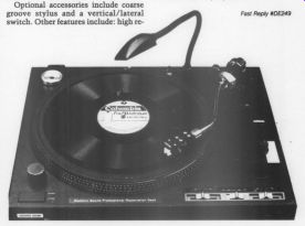
Esoteric Sound has introduced a fully manual turntable featuring not three, but six speeds. The multi-speed phonograph disc player gives accurate reproduction of modern LP discs, 78s, and vintage records. The V2 Professional Restoration Deck is modified to six speeds, 33, 45, 71.29, 76.59, 78.26, and 80rpm. Speeds are switch selectable.
Optional accessories include coarse groove stylus and a vertical/lateral switch. Other features include: high re liability direct drive motor, standard cartridge headshell design, adjustable tracking and anti-skating force, pitch control, solenoid brake, and operable from 120V AC or 240V AC at 50-60Hz. Including dustcover, the price is $375.
For further information, contact Esoteric Sound, 4813 Wallbank Ave., Downers Grove, IL, 60515.
---------------
The Analog IC Data Book, Volume 10 has been released by Precision Monolithics, Inc., offering 1,800 pages of in formation for analog designers. The book covers PMI's line of linear and con version ICs in CMOS, Bipolar and Bi CMOS technologies. The op amp section contains definitions, selection principles and AC and DC considerations.
The selection guide, based on 12 parameters, simplifies op amp product selection according to speed, noise, precision or micropower requirements. To receive a free copy, call (408) 562-7470 or (800) 843-1515, FAX: (408) 727-1550. Precision Monolithics, 1500 Space Park Dr., Santa Clara, CA 95052.
------------------
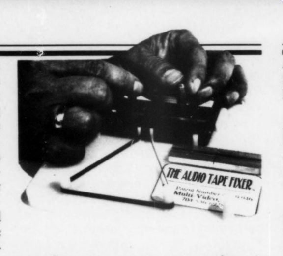
Don't you just hate it when you pull an audio tape out of the player and it looks like a fork full of spaghetti? Or you put a tape in and it sounds like it's playing backwards? There is a solution. The Audio Tape Fixer, from Multi-Video, Inc., holds the tape still, leaving your hands free to advance the tape in either direction by turning the spindles manually or with a cordless screwdriver.
Audio tape twists can be located and corrected by looping the tape around the spools on the front of the Fixer, advancing the tape to the first twist, correcting it by hand and repeating the process.
The unit will hold two cassettes at once, making it possible to transfer a tape from a damaged cassette to a new one. An aluminum splicing block is attached to the work station for ease in repairing broken tape and in transferring tape from one cassette to another. A sheet of pre-cut splices is included in the $29.95 price.
For more information or to place an order, contact Multi-Video, Inc., PO Box 35444, Charlotte, NC 28235, or call 800 289-0111.
--------------------
Interest in analog sound processing has prompted PAIA Electronics to again offer its Hyperflange and Chorus kit in its line of sound processing kits.
Designed by Craig Anderton, the kit is useful in the studio, and for live processing. A hyper triangular control oscillator allows linear time sweeps, and exponential time sweeps the human ear prefers, both over a range of 71:1.
The unit is designed to mount in a single 13.5" standard rack space, and requires a +12-15V, 200mA power supply.
The Hyperflange and Chorus kit includes printed circuit board, all compo nents, controls, and hardware, and an il lustrated step-by-step assembly and user's manual for $139.95, plus $2 ship ping. An optional black anodized front panel with printed control designations is sold separately at $15.95, plus $2 ship ping. Both are available from PAIA Elec tronics, 3200 Teakwood Lane, Edmond, OK 73013, (405) 340-6300.
---------------------
AudioSource has unveiled the SS-Three Surround Sound Processor featuring Dolby Pro Logic.
Working closely with Dolby Labs, AudioSource incorporated the new Pro Logic chip for the SS Three to achieve a more defined positioning of sound, providing a more realistic effect over a wider area of the listening space.
The SS Three features a built-in 30W rear channel amplifier with a line out for the center and subwoofer channels, plus an additional line out for surround, for those consumers who choose to use a higher-powered amplifier.
Other features include: a high-powered toroidal power transformer, a switchable subwoofer crossover, variable subwoofer output level control to match any amplifier configuration, and special effects modes including Matrix, Hall, and Dolby Surround.
Also included is a switchable digital time delay, auto sequential test tone, as well as auto balance and auto calibration for left and right input signals to assure proper signal tracking with pinpoint ac curacy.
Front panel controls are duplicated on the full function, infrared remote control, including power/off, surround function selector, test tone, time delay, rear, center, and master volume.
The AudioSource SS Three is priced at $399. SS One and SS Two models currently retail for $199.95 and $249.95 respectively.
For information contact AudioSource at 1327 North Carolan Ave., Burlingame, CA 94010, or call (415) 348 8114.
AudioSource has released its isomat portable compact disc isolation system.
Joining AudioSource's line of audio accessories, including the LLC-One Laser Lens Cleaner, the isomat is designed to enhance performance of CD players.
The biggest problem with CD players, especially portables, is vibration. Originating from loudspeakers and other noise sources, vibrations are transmitted through shelves, desks, countertops, walls, etc. Most affected by vibration is a CD player's optical pickup assembly, servo system, and power supply.
The isomat pad is made of a material called poron cellular urethane, known for its energy absorption, and damping capabilities. For rigidity and additional damping, the pad is supported by a plat form made of acrylonitrile butadine styrene (ABS).
The isomat system rests on three conical-shaped feet, much like the 'pointed feet’ isolators audiophiles use for CD, turntable, and speaker stands. This de sign affords stability, while limiting con tact between the support surface and the isomat system.
The isomat pad measures 5" x 7", the entire system 8" x 5.5 ". Suggested retail price is $29.95. For more information, contact: AudioSource, 1327 Carolan Ave., Burlingame, CA 94010, or call (415) 348-8114, FAX (415) 348-8083.
++++++++++++++++
Also see: