I HAVE ALWAYS been irritated when I must get out of my best listening chair to adjust my stereo system's volume or balance. I am sure you, too, have often needed to adjust the controls several times before finally getting them right. And the better the equipment, the more sensitive the balance adjustment becomes. Placing the control amp near your seat isn't practical-making re mote control (RC) the only solution.
Sadly, the high-end equipment we so value does not come with RC, and the stuff that is available with RC doesn't live up to the expectations and quality requirements of serious audiophiles.
That leaves one choice: roll your own.
I have experimented with voltage controlled amplifiers, light-dependent resistors, FET attenuators, and switched attenuators. The VDR circuit was an ingenious closed-loop design with an ideal log control curve. I was quite proud of it, but it had too much noise for serious applications. The best I came up with at the time was a digitally switched attenuator with a 60dB range in 1dB increments.' It was driven by a couple of IC counters and was controlled by a single screened cable. This unit served me well for ten years, but it added two op amps and several IC switches in the signal path. In the following years, I discovered it was extremely important to limit the amount of active circuitry, and solder and switch contacts, in the signal path.2 :
--------------
ABOUT THE AUTHOR: J.M. Didden is a career-officer in the Royal Netherlands Air Force, currently working in Quality Assurance with defense contractors. Prior assignments were with Air-Defense units and a stint as a programmer for Command & Control systems. He built his own audio system, from CD-D/A converters to speakers. Several of his designs have been published in Audio Amateur. The author's motto: 'Murphy's Law’ is just an excuse for sloppiness.
-------------
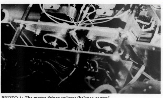
PHOTO 1: The motor-driven volume/balance control.
------------
As an example, consider the following. Normally, each end of the signal interconnect cables in your system is connected to RCA plug/socket pairs. I soldered one end of each signal interconnect cable in my system directly to the board it was leaving, deleting eight solder joints and four plug connections for each channel.
I modified one channel, then com pared both with mono music. The difference was not always audible, but with strong, extended mid-bass sound, the system showed a definite improvement. Depending on the quality and state of plug connections, differences might be more pronounced. The best plug is still no plug. Although my digital attenuator was certainly of high quality, it degraded the signal more (in con trolled environments, audibly more) than a good quality audio pot. So I built myself a couple of remote-controlled volume/balance controls with motor driven Alps pots.
Step Right Up
The concept I used in the digital attenuator had proven itself. It let me adjust the volume without changing the balance setting, and adjust the balance without changing the overall level. This is difficult to achieve with conventional volume/balance pots. The only way to do it is by using a single volume control per channel. It also eliminates two more solder joints and a wiper contact from the signal path.
When working with the balance, the preferred method is to adjust each control simultaneously in opposite directions. This can get tricky with manual control, but is easy with motor-driven pots and some logic chips. I used step per motors with 200 steps per revolution, about 167 steps for full pot rotation-how's that for a stepped attenuator? It gives incredibly fine balance control.
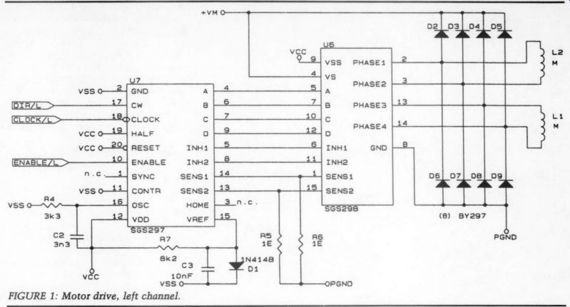
FIGURE 1: Motor drive, left channel.
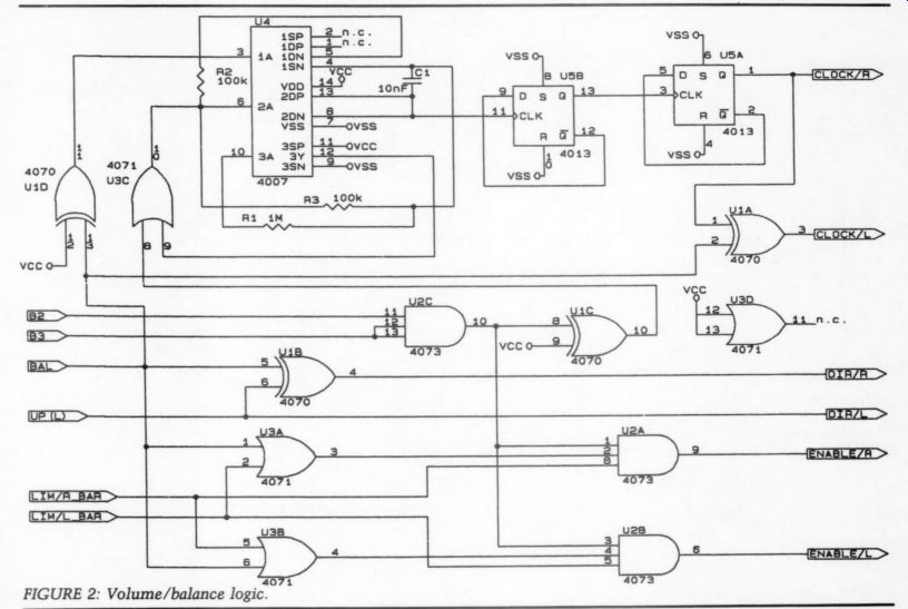
FIGURE 2.
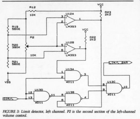
FIGURE 3: Limit detector, left channel. P2 is the second section of the left-channel
volume control.
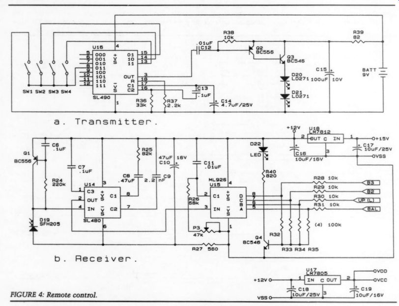
FIGURE 4
In volume-control mode, both motors drive the left and right channel pots simultaneously in the same direction. Because they step in sync, the tracking is dependent only on the pot's tracking. In balance mode, each motor is stepped in turn-one clockwise, the other counterclockwise. Also, in this mode, the step rate is reduced to allow precise control. The resolution depends on the position of the wiper, but is at least a fraction of a decibel. If you listen to music with very good localization, this balance control lets you position the sources almost to the inch.
Figure 1 shows the motor circuitry for one channel. It uses two special ICs from SGS.[3] These contain the necessary logic and drive circuitry. Note the three input signals: “Enable ” activates the circuit and powers the motor, “Clock” is the step rate input, and “Dir ” determines the direction of rotation.
Balancing Act
The volume/balance control logic is shown in Fig. 2. The circuit generates the three control signals for the motor circuits. It is much simpler than it looks. U4 generates the step clock, which is divided by U5A and U5B to get a 50% duty cycle. The rate is reduced if the BAL line is a logic 1 (through U1D, which serves as an inverter).
I got this variable-rate clock generator from Melen and Garland. Signals B2 and B3 must both be logic 1 for the circuit to respond to the BAL and UP/L commands. These are used in the remote control (discussed later).
The BAL line determines whether U1B transmits the UP/L signal directly to DIR/R (BAL = logic 0) or inverts it (BAL = logic 1). If BAL is logic 1, DIR/R and DIR/L are of opposite polarity.
That's the balance mode: the motors turn in opposite directions. UP/L deter mines which one turns which way; it controls whether the balance shifts to the left or to the right. (As its label implies, the balance shifts to the left if it is 1.) U1A adds a refinement. Again, if BAL = 1, U1A inverts the CLOCK/R signal. The two clock signals are of opposite polarity and the effect is that the motors are stepped alternately, adding even finer control. When BAL = 0, CLOCK/L is identical to CLOCK/R and DIR/R is identical to DIR/L. This is the volume control mode, and UP/L determines the direction (an increase in volume if UP/L = 1). Simple.
If you were wondering about the LIM signals, you must provide for the motors to stop at the end of the pot's mechanical travel (Fig. 3). The pots are actually dual (stereo) pots; one section is used to control the audio level, the other provides position feedback to the limiting circuit. P2 in Fig. 3 is the feed back section.
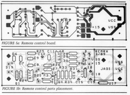
FIGURE 5b: Remote control parts placement.
The dual comparator U10 compares the wiper voltage to the limit voltage at the R13/R14 and R14/R15 junctions.
If either limit is exceeded, a logic 0 is generated to the U11 circuit. Here it is combined with the direction signal to generate the limit signal LIM/R for Fig. 2. (The BAR means that the logic is inverted: if LIM/R is 1, limiting does not occur in the right channel.) Why is the direction signal necessary? Suppose you halt because you have reached the lower limit. You could never recover; you are limiting and the appropriate ENABLE line to Fig. 1 is blocked. But you would like to back out by increasing the level. A reversed DIR/R signal combined with the 1 signal from the other comparator, which is not limited (U10A, in this case), makes it possible. A similar argument applies to limiting at maximum level.
There's more
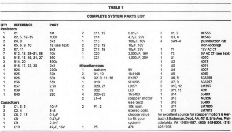
TABLE 1 -- COMPLETE SYSTEM-- PARTS LIST, Miscellaneous; An excellent source for stepper motors is Herbach & Rademan, Dept. AA, 401 E. Erie Ave, Philadelphia, PA 19134-1187, (800) 848-8001, (215) 4261708.
Now consider the following. In balance mode, if one pot limits, the other will still respond, giving you maximum balance range; you can turn one channel fully down and the other fully up.
In volume mode, if one channel limits, both stop, so the balance setting is preserved. (Look at the circuitry around U3A and U3B in Fig. 2.)
Doing It from a Distance
The circuitry described above can function as a stand-alone, high-quality volume/balance control. Adding switches to the control inputs lets you use this system with your own equipment.
I wished to use the circuitry in a re mote control setup. I opted for IR RC because of the availability of ICs and application information for these circuits.
The setup I used is a slightly modified application note from Plessy Semiconductors of Great Britain. The schematic diagram is given in Fig. 4. The transmitter section is powered by a standard 9V battery.
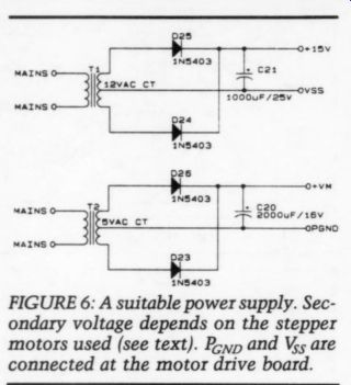
FIGURE 6: A suitable power supply. Secondary voltage depends on the stepper
motors used (see text). P_GND, and V_SS are connected at the motor drive board.
The SL490 can respond to a total of 16 switches for 16 commands, but I used only four (balance to right and left and volume up and down). D20 and D21 are the transmitting IR diodes. The Puls position-modulated signal is received by D19 and the SL480 and decoded by the ML926.
For correct operation, the internal oscillator of the ML926 must be synchronized to the transmitter's oscillator. This is done with P3. The procedure is simple: while pushing one of the transmit-buttons, P3 is slowly turned until LED D22 lights.
The connections of the four transmit switches were not chosen arbitrarily.
Note that the ML926 has a 4-bit output bus for decoding the 16 possibilities (labeled A, B, C, D). By connecting the switches as indicated, I was able to avoid decoding the output. Whenever one of the switches is pressed, B2 and B3 both are 1. That leaves four combinations of the UP/L and BAL outputs, as described above.
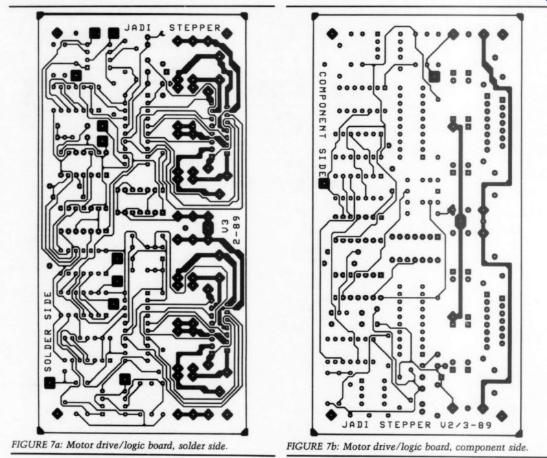
FIGURE 7a: Motor drive/logic board, solder side.
FIGURE 7b: Motor drive/logic board, component side.
You could use the other switch combinations for further commands--implementing remote switching of source, tape/monitor, and so on, for example.
I decided to save that for a future project. The remote control receiver is on a separate board (Fig. 5). The transmitter is so simple, no board layout is given.
The best is to use perfboard and build it into one of those small hand-held cases available for such a purpose.
Power It Up
The circuitry requires several supply voltages. The logic circuitry needs 5V, the RC receiver needs 12V, and the step per motors need voltages between 5 and 24V at currents between 100mA and 1A.
See the next section on motor selection.
The RC transmitter has a 9V battery.
The RC receiver board contains the volt age regulators for the 12 and 5V sup plies. That means you need only a 15V raw supply capable of approximately 400mA, plus the motor supply, which can be unregulated. A suitable power supply system is shown in Fig. 6. This can be assembled on a small piece of perfboard. Note that the V_SS and P_gnd lines are connected on the motor drive board.
Construction/Parts Selection
Give careful thought to the mechanical construction of this system. Stepper motors generate vibrations when operated.
Although the motors are switched to standby when idle (this is most of the time), their operation can be audible. If you use the mechanical assembly as shown in Fig. 8, you won't hear them step unless you are within 2 or 3 feet of the enclosure. The construction also gives a measure of shielding between the motor and logic circuits and the volume pots. Vibration can be further lowered by appropriate choice of supply voltage and current limit resistors (R5, 6 in Fig. 1); more on this later.
------------------
CAD Support
For the board layouts and other drawings, I used several CAD programs on an AT clone and an Epson LQ1050 printer. Although these programs are not in the amateur's price range, readers might be interested in them or have access to them at school or on the job.
Artwork V 1.4 R4, Wintek Corp. 1801 South St., Lafayette, IN 47904 2993. About $800, used for all board layouts.
Or CAD/SDTII, Or CAD Systems Corp., 1049 S.W. Baseline St., Suite 500, Hillsboro, OR 97123. About $600, used for all schematic drawings.
DruckerPlot, Epson, Germany.
About $75, used to convert the plotter outputs (HPGL-format) from smArtwork and OrCAD for output on the matrix printer. The parts layouts are made by first printing the board copper plane in a gray scale and later superimposing the silkscreen layer in full black. smArtwork produces both layers. DruckerPlot is available in the US from Insight Development Corporation. Contact your Epson dealer.
A similar product is available from NEC for its line of printers (PinPlot).
A generic plot converter called FPLOT is available from FPLOT Corp., Suite 605, 24-16 Steinway St., Astoria, NY 11103 for about $65. [The current revision of Or CAD contains all necessary printer and plotter drivers needed without further programs.
-Ed.
------------------
The step rate (speed) of the motors is controlled by the circuitry around U4 in Fig. 2. You can change it by altering the value of C1. The larger C1 is, the slower the motors step. The ratio of volume control speed to balance control speed is set by the ratio of R2 to R3. The lower R2 is, the larger the ratio. Mount the RC receiver detector D19 behind a hole in the front panel. You can cover the hole by a piece of transparent red foil for a pleasing appearance. Use screened cable for both leads of the diode.
Most of the parts used are standard and readily available. The only possible exceptions are the IR transmitting and receiving diodes (D19, 20, 21) and the ICs used in the RC system, the motor control's SGS297 and 298, and the step per motor itself.
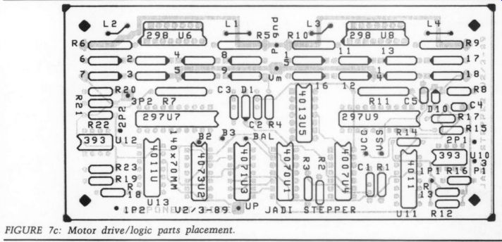
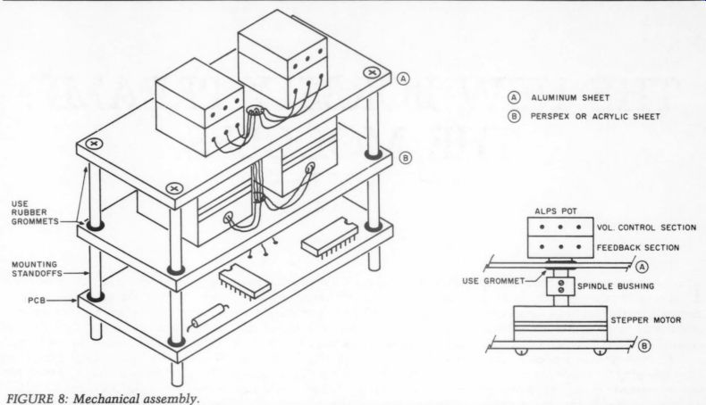
FIGURE 7c: Motor drive/logic parts placement. FIGURE 8: Mechanical assembly.
You can find many types of motors on the surplus market. For them to be useful for this project, you need motors with four leads (two windings) called bipolar motors. Motors with two split windings (unipolar, five or six leads) cannot be used without modifications to the circuit.
Step sizes vary widely from 30° (12 steps per revolution) to 0.9° (400 steps per revolution) or less. Your best bets are stepper motors used in floppy disk drives; they offer 100-400 steps per revolution at a power consumption of less than 1A at 5-12V.
I found a couple of Tandon motors sized 1.5 ” by 1.5 ”. They were specified for 12V/800mA, but I run them at 8V.
That makes them quieter and they take only about 0.5A.
The mechanical force needed to turn the pots is relatively low. Therefore, experiment with the supply voltage. Try to find the voltage where the pots are still turned reliably. You can test it by trying to stop the motor by grabbing the spindle. It's easy to get a 'feel' for the force sufficient to turn a pot.
The current limit resistors are another area for fine-tuning (Fig. 1). The reference voltage generated across D1 is com pared with the voltage across R5 and R6, which carry the motor current. The motor is inductive; when switched on, the current increases like a sawtooth current. When the voltage across R5(6) reaches the reference voltage across D1, the motor current is reset and turned on again. This produces a sawtooth current with the average value of the current drawn from the supply, but, of course, the peak current is more (maybe up to twice as much).
After you have found the supply volt age for reliable operation, see if raising or lowering the value of R5 and R6 reduces motor sound level. You can ad just them between one-half and two times the value for the motor's nominal current. The reference voltage across D1 is about 0.7V.
You may think this empirical information makes it too complex. This is not true, however; you can run the motors on the supply for which they are specified without any problems. This will give you what I consider the ultimate volume/balance control in terms of quality, ease of use, and resolution.
This is true even without remote control. My problem is I am a perfectionist.
Wringing just a little bit more performance out of a part or unit gives me great pleasure.
REFERENCES
1. Didden, ].M., 'Programmable Audio Attenuator,’ Wireless World, May, June 1980.
2. Didden, ].M., 'Audio Components Design: A Systems Approach,’ TAA 2/88, p. 27.
3. SGS Semiconductor Corp., US Head quarters, Phoenix, AZ, (602) 876-6100. Ask for data book Power Linear Actuators.
4. Melen, Roger and Harry Garland, Understanding CMOS Integrated Circuits, 1975, Howard Sams Co., ISBN 0-672-21129-7.
++++++++++++++++
Also see: