DEPTS.
- Intro
- EDITORIAL
- Kit Review
- Ask TAA
- AUDIO AIDS
- JUST LOOKING
- LETTERS
Intro
You can't completely eliminate noise in equipment, but L.B. Dalzell explains how you can reduce what the power line is adding to get a purer sound.
Mendel Kleiner describes an amplifier for electrostatic headphones, aid for experimenters wishing to extend the voltage range to reach ELS levels.
Most high-end equipment lacks remote control. For the design and construction of a remote volume/ balance control system you can use with your equipment, turn to J.M. Didden's article.
After receiving many letters from eager readers, Erno Borbely pro vides us with the layouts for his preamp modules.
William Sommerwerck reviews the Heath ET-1000 Circuit Design Trainer, a combined breadboard and power supply.
------------------
This publication is available in microform, from University Microfilms International. Please send information about these titles:
Name Company/ Institution Address City State
Call toll-free 800-521-3044.
Or mail inquiry to:
University Microfilms International. 300 North Zeeb Road, Ann Arbor, MI 48106.
Editorial
Biting the Byte Question
Every serious audiophile who has any technical inclinations at all, which I must assume includes the majority of this magazine's readers, has contemplated the “shall I get a computer? ”' question. Not simple. Most of us probably view the idea for the first time with a curious mixture of excitement and foreboding.
Learning a new discipline always seems daunting to most of us. Fortunately we seldom see the full scope of what the discipline entails, else we would probably not venture into some new areas at all. The news about computers is a mixed message at best. 'User friendly' is somehow no more convincing to the newcomer contemplating the strange world of bytes, bits, hexadecimal, and other arcane terms than the used car dealer who refers to himself in newspaper and TV ads as 'Honest Harry. ” On the other hand, the braggadocio component in testimonials from those who use such machines every day is not very com forting either. Although the terms 'unreal' and “incredible ” have somehow become accolades in our lifetimes, we know in the pits of our emotional stomachs that the original meanings of those words really do apply to computers.
The world of computers has, however, exploded into almost every human activity during the last decade, surprising nearly everybody, including the developers. And no end to the evolution of computing machines is in sight. They continue to improve and to decrease in price.
My favorite example of the latter is our purchase of our first “fixed” or “hard ” disk for mass storage of computer data in 1981. The unit weighed 70 pounds, drew several amps at turn on, and cost almost $7,000. It could store 64 million bytes, or 8-bit words, on its multiple platters and was very noisy indeed.
Our most recent acquisition stores 200 million bytes, costs $700, weighs nearly two pounds, and can hardly be detected when it is running.
Computers, like most industrial products, plummet in price if the quantity rises. Today, a small IBM clone computer can be put together for half the cost of an IBM Selectric typewriter.
The personal computer population of the US is well above the 20 million mark as of January of this year. All of that raises the question of whether you ought to have one.
What can they do? For most people they are first of all a wonderfully efficient way of capturing text in a form that stores in a tiny, cheap space, is easily retrievable, editable, and reproducible. Second, computers store names, addresses, and phone numbers not only easily, but make the information easily accessible in sorted order for keeping track of friends, business associates, or groups of all kinds.
The third use, in what are known as spreadsheets, is the end less world of computation. The spreadsheet is a two dimensional calculator of genuinely awesome power. It has, for the most part, displaced the calculator since it can clone any calculator function. Even simple computers can be equipped with highly sophisticated calculators which emulate very expensive devices.
But there is far more computers are capable of doing: They capture schematic diagrams, do complex drawings in two or three dimensions, dial your telephone, access other computers and databases on them. They can be used to simulate electronic designs, test them, and present results before building the device.
The list is probably literally endless. But for audio amateurs, the computer becomes important as the centerpiece in gathering performance data of existing equipment, providing signals for the tests, and displaying data in oscilloscope-like graphics.
Test results can be graphed on screen or output to printing or plotting devices.
Ok, ok, so you're convinced. But where and how do you be gin? Obviously it is probably easy to make a costly mistake without adequate information. Certainly this is true. And the subject is vast, rife with conflicting opinion, with gurus a dime a dozen-most of them with multi publications to their credit, whether creditable, credible, or not.
I confess to having read quite a lot of the periodical and book offerings at first because our company's business cannot survive without good computers and good software. But a technical appetite carries me, as I suspect it does many of you, beyond the pragmatic considerations. It isn't that computers are fun, exactly, but they are complex and quirky enough to lure one into pursuit of optimum performance and capability. And for some they are a hazard of addiction to games of amazing sophistication: virulently habit forming in some cases.
But this is not the place to offer a full access path for your decision. I am very happy, however, to offer three places to begin if you are reasonably convinced that a computer is in your future.
Three veterans of the computer wars have pooled their knowledge and resources to produce what I consider one of the best books I have seen for the technically literate beginner who wishes to understand the most pervasive of the computer choices: IBM's PCs and their clones. Corey Sandler, Tom Badgett, and Wade Stallings have written a brief, concise over view of the prime issues of the PC under the title PCs From Scratch (Bantam Computer Books, 239 pp., $19.95). The book not only serves as an excellent overview of the issues, but shows you how to put a PC together for yourself. (Having assembled a few, I can attest to their accuracy and helpfulness.) John Woram, an author familiar to many audiophiles, has written a useful companion volume to PCs From Scratch with the title: The PC Configuration Handbook (also from Bantam Computer Books, 728 pp., $28.95). This is a fine reference volume for keeping the hardware maintained, or upgrading it after you have acquired or built your machine. Also well worth considering, perhaps later, is Upgrading and Repairing PCs by Scott Mueller (QUE, Inc., 728 pp., $27.95).
After all the hype has been discounted and the purple prose swept aside, the computer is a distinct, major advance for anyone with technical interests. The computer for some becomes a mere appliance. For others it becomes an intriguing artifact worth major investments of time and learning. But I commend the ma chine, and the journey, to you as an audio amateur. It can implement many tasks in your pursuit of good sound with a speed, accuracy, and efficiency impossible otherwise.
-E.T.D.
Kit Reports
CIRCUIT DESIGN TRAINER
Reviewed by William Sommerwerck Heath ET-1000, Heath Co., Benton Harbor, MI 49022, (616) 982-3200, FAX (616) 982-5137, (800) 444-3284 to re quest a catalog. Kit $219.95; assembled $299.95; spare breadboard $29.95.
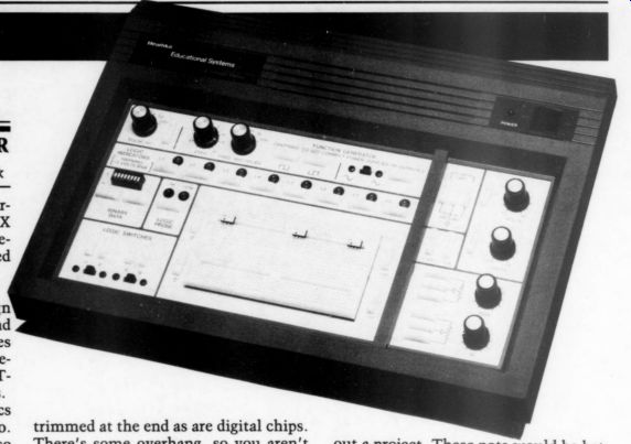
THE HEATH ET-1000 Circuit Design Trainer is a combined breadboard and power supply. Several of its features make it especially attractive to digital de signers, but they do not limit the ET 1000's usefulness to analog designers.
The term “breadboard ” in electronics goes back to the earliest days of radio.
Commercial radios were inaccessible so experimenters often constructed receivers on wooden breadboards. Some technical historians say people were so poor they couldn't afford a metal chassis. I doubt it. Vacuum tubes and other electronic components were so expensive anyone who could afford them could also afford a metal chassis. I suspect bread boards were popular because most people lacked the tools (and the skills) to work with sheet-metal. Breadboards were in expensive, nonconductive, and you could easily attach components to them with wooden screws.
I don't know whether professional engineers designed prototypes on wooden breadboards. However, the large working area and easy access to components certainly made breadboards attractive for prototypes. For whatever reason, the term has stuck and building an electronic prototype is called “breadboarding ”--regardless of the surface used.
A modern electronic breadboard has nothing in common with the traditional kind.! It's a block of perforated plastic.
Rows of springy metal strips sit behind the holes. When you stick a wire in a hole, the strip grips it. Each spring strip extends across four or five holes, so it's easy to connect several components without having to solder them. The hole layout and spacing have evolved to accommodate integrated circuits. Holes are generally on 0.1 ” centers to match the spacing of most DIPs and SIPs. The board is divided into two rows of spring clips and the IC straddles the gap.
The removable breadboard on the ET-1000 has two independent sections, each of which has 48 five-hole strips on either side of its gap. That means you could insert up to twelve 16-pin digital ICs (48 x 2/8 = 12). Analog chips aren't trimmed at the end as are digital chips.
There's some overhang, so you aren't able to insert as many.* One of a Kind? The ET-1000 is not unique. ACE and several other firms have long manufactured breadboarding systems consisting of compact metal boxes with one or more power supplies inside and their own breadboards on top. These products rep resent fairly good value if you don't need function generators, logic probes, volt meters, and other paraphernalia.
Many designers do need them, however, and prefer to have them conveniently at hand. This explains the appearance of several 'prototyping stations,' of which the ET-1000 is one. For example, the current Jameco catalog shows the PB-503 and JE-450, aimed at analog and digital designers.
The feature that sets the ET-1000 apart from other prototyping stations-and the one I think will sway most users in its direction-is its five power supplies, all regulated and short-circuit protected:
+5V, 1,000mA: This is the basic digital supply. It also powers the ET-1000's logic displays and switches (described later).
+12V, -12V (500mA each): This balanced pair has many uses; CMOS circuits and op amps are obvious ones.
These supplies are isolated; they do not track.
+20V, -20V (500mA each): These are independently variable, from 1.2-20V.
The maximum current available varies with the voltage, from 150mA at 1.2V to 500mA at 20V.
I do have one serious quibble with the power supplies. The pots for the variable voltage supplies are at the upper-right corner, where they aren't likely to be bumped. But “unlikely ” is not “impossible. ” However remote, there's always the chance you might hit one and blow out a project. These pots would be better if they had a lock on them.
Assembled? No Hay Problemo!
Assembly was simple, and everything worked perfectly the first time. There were no tight mechanical spots, though it does take a bit of jiggling to organize the twisted power cables neatly inside.
Heath rates the ET-1000 at level-2 complexity, but the kit really has nothing to intimidate a beginner (except intimidation itself). I ambled through assembly in about 20 hours, but a more efficient worker could probably knock off the ET-1000 in ten hours or so.
You must, however, replace some of the screws. Heath supplies eight #4 by 3/8 ” self-tapping screws (diagram key F2) that attach four heatsinks to the power supply board. They are made of some incredibly soft metal that shears after only a few turns into the aluminum.
Take one to a hardware store and find steel screws of about the same size.
You'll also find assembly easier if, before mounting the heatsinks, you tap them with the steel screws.
The ET-1000 is a nice-looking unit (something that can't be said about every Heath product). The cabinet is cocoa brown with crisp edges and an appealing wedge shape. The ventilation holes are part of the design and enhance its appearance. The tilted panel makes the board, connectors, and knobs easier to see and reach.
The power transformer is large and adds stabilizing mass. That, and the large rubber feet, reduce the chance the ET-1000 will go skidding off a bench top.
Despite the weight (8.41bs), it's easy to grab the ET-1000 by the front edge and carry it, even though the cabinet lacks a handle.
Useful Utilities
The ET-1000 is more than power supplies and a breadboard. It has a number of utility circuits to simplify designing and testing. Most of these are for digital de sign, though the function/pulse generator can be used for analog, too. The function generator (using the ubiquitous Exar XR2206 chip) offers five switched frequency ranges, from 1Hz-10kHz. A separate pot varies each range through a 10:1 ratio.
The function generator offers three waveforms. Two are square wave out puts, of opposite polarity. A third output terminal delivers sine or triangle waves, switch selected.
If that isn't enough, there's a fourth:
pulse output. The pulse width can be set at 2,000, 200, 20, 2, or 0.24S. The pulse width is constant, regardless of frequency (unless, of course, the pulse is wider than a half-cycle of the selected frequency).
Below the function generator section is a row of eight green LEDs. One turns on when a TTL logic high is applied to the connector strip below it. These LEDs can be used to monitor specific circuit points or to display byte-width data.
Complementing these LEDs is an eight position DIP switch with an eight-output connector block. You can set any of the eight outputs TTL high or low with the corresponding switch.
To the right of this circuit is a “logic probe ” with red and green LEDs. Normally, neither is lit. Applying a TTL logic low to the input below lights the green LED; a logic high lights the red LED. The last digital utility is two banks of high/ low logic outputs. A spring-loaded switch below each pair toggles the high to low, and vice versa. These are useful when you wish to toggle a signal or trigger a circuit.
The right-hand side of the board contains the + 12V outputs and the plus and minus variable outputs, along with the latter's adjustments. If you wish to set up your own power supply, Heath thoughtfully brings out the dual 15V transformer taps on the front panel. Finally, the unit has 1k and 100k linear potentiometers.
Half a Loaf
The breadboard isn't especially large- only 960 points. (You can bet Intel won't be using the ET-1000 to prototype the 586i.) However, the breadboard pops off.
Heath supplies a pry tool, but I had no trouble grabbing the board at the edges and lifting it. With a second breadboard (Heath kindly honored my request for another), you can swap circuits quickly and you can always buy a bigger breadboard and place it in front.
The breadboard is itself a kit. Not only do you screw the positioning pins to the bottom of the board, but you actually insert the contact strips in the board: a great way to get some intellectual stimulation while watching Wheel of Fortune.
A breadboard is useless without jumpers, and Heath is parsimonious. They supply long lengths of solid wire, which you're supposed to cut to length (easy) and strip (irritating). Like Liebnitz (who objected to the manual labor of mathematical calculations), I have better things to do with my time, ” so I bought ready-cut jumpers from an electronics supply store. Unfortunately, a bag of 600 jumpers (of varying length) costs $25.
(That's not a misprint.) I don't under stand how a piece of machine-cut wire can cost four cents. You'd think Heath would have enough scraps they could recycle via the ET-1000.
Measurements and Specs
I used a Fluke 87 multimeter? to check the supply voltages. Unloaded, the + 5V supply measured 4.84V. The + 12V and -12V supplies measured 12.28 and -12.17V. The positive variable supply ranged from 1.29-23.04V. The negative variable type ranged from -1.30 to -23.19V. All the voltages drifted upward about 1% as the unit warmed up.
The fixed supplies were within 5% of their nominal value, a reasonable tolerance. The +5V supply was more than 3% low, which although within spec, seems to be a common problem with 7805 regulators. You rarely see them higher than 5V.
Heath says the supplies will tolerate an indefinite overload. That sounded like a fun thing to test. I shorted out all five supplies, one at a time, for at least one minute. They all survived, unscathed, with no fuses blown or parts popped.
In addition, I checked the function generator. The 1-Hz range was limited to 0.73-7.96Hz, suggesting the capacitor for that range was too large. The low end of the other ranges could not reach quite as low as specified (though the lowest frequency was never more than 3% high).
The high ends went a bit higher than spec, making things more even.
-------------------------

Description: breadboarding system with five power supplies, function generator, digital probe, and logic switches/indicators Power supplies:
+5V DC at 1000mA, regulated
+12V DC at 500mA, regulated
+12V DC at 500mA, regulated
+1.2 to +20V, variable regulated, 150-500mA
-1.2 to -20V, variable regulated, 150-500mA
Load regulation:
5V supply: better than +2% 12V supplies: better than + 1% variable supplies: better than +2% (V,,, = 5V, [,,, = 10mA)
Function generator:
sine, square, and triangle waveforms, 1-100kHz ranges: 1-10Hz, 10-100Hz, 100-1kHz, 1k-10kHz, 10k-100kHz pulse widths: 2mS, 2004S, 20uS, 2uS, 200nS
Logic switches: two; momentary-contact, spring-loaded; complementary +5 and +0.2 outputs
Binary data and test: eight miniature switches in a DIP; complementary +5 and + 0.2 outputs eight green LEDs with separate terminals logic probe with red (high) and green (low) LEDs; threshold 1V 1k and 100k linear potentiometers
General: power requirements: 105-130V or 210-260V RMS, 50/60Hz, 95W minimum dimensions: 15.5 “ x 10.5 ” x 4.5 “ (40.0cm by 27.0cm by 12.0cm) net weight: 8.41bs. (3.8 kg)
-------------------------
The pulse widths were as specified, with my Philips PM 3217 scope showing the errors leaning toward too wide a pulse (rather than too narrow). The sine and triangle outputs worked as advertised. The sine looked a bit more flat topped than it should, though. Also, both waveforms had an extremely narrow spike at both the positive and negative peak of the waveform, about 14S wide.
I don't know what caused it. It was not affected by either the generator frequency or the pulse-width setting.
To Buy or Not to Buy?
You can buy an assembled prototyping station for about what this Heath kit costs. On the other hand, the Heath ET-1000 uses parts of known quality and has a sturdy case. (Oriental manufacturers just don't seem to understand what good plastic is.) The ET-1000 is a bit pricey (but only a bit). I'd rather buy a product from an American firm likely to be around for awhile. Most of the parts are off-the-shelf items, and the fact the ET-1000 is a kit makes it easy to maintain (or even modify). My only real quibble is Heath's failure to provide a good selection of pre stripped jumpers. Taking all this into account, the ET-1000 represents value for the money, and I have no hesitation recommending it.
REFERENCES
1. Well, they're both flat and rectangular actually. The modern ones vaguely resemble matzos, sort of an unleavened breadboard. I have a Jewish co-worker who hates matzos: “The bread of affliction, ” he says. I love them, especially with cream cheese.
2. Atone time, these products were called “solderless breadboards. ”'
3. John Curl told me about early bread boarding devices of the late 1960s and early 1970s, which used free-standing spring clips or banks of metal fingers. They were over sized, clumsy to use, and expensive.
4. I once nearly ruined a project at Bendix because of this “subtle ” difference.
5. You can buy whatever accessories and test equipment you need, but the whole point of a prototyping station is combining a bread board with power supplies. The more power supplies, the merrier.
6. Heath uses the same heatsinks and soft screws in other products. You are warned.
7. Assembling a kit could be considered entertaining or educational, but cutting and stripping wire is mindlessly tedious.
8. Multimeter' is an understatement.
You cannot believe the number of features this baby has, including min/max, 24-hour averaging, hold, pulse width, frequency, capacitance, true-RMS readings, and continuity. About the only useful feature missing is a decibel scale.
Ask TAA
By Gary A. Galo, Contributing Editor
YOUR POWER LINE: JUST 60Hz?
AUDIO AMATEURS are known for paying a great deal of attention to details when designing and building equipment. Your last preamp project may have included an ultra low noise RIAA phono section, flat to within 0.1dB; a high slew rate, low-impedance, buffered line stage; actively buffered tape outputs; silver con tact switches; polypropylene capacitors; metal film resistors; oxygen-free internal wiring; and a tightly regulated, low impedance power supply. You probably finished the project confident all bases were covered and no performance limitations were left that might get between you and the music. Right? Unfortunately, probably not.
No matter how carefully you design and build equipment, you usually fail to address one item critical to the performance of the audio system: the AC power line. Ideally, the alternating cur rent available at power outlets should be a clean 60Hz sine wave, with no harmonic content. In practice, this is rarely the case. First, the power company probably doesn't supply a distortion-free waveform to your outlets. But this is only a small part of the problem. Between the generators and outlets, all kinds of garbage gets dumped on the power lines.
Some of this interference is introduced in your home. Among the worst offenders are fluorescent lights and the switching power supplies most personal computers use. Both generate high-frequency electrical interference, called RFI (radio frequency interference), along with line hash at frequencies below the RF region.
Electric motors and appliances generate another type of noise as well, EMI (electromagnetic interference). Neighbors' appliances and equipment generate more RFI and EMI. These types of interference can also be dumped on power lines by industrial machinery and can be picked up inductively from radio transmitters.
The Fluorescent Light Problem For many years, I noticed inconsistencies in my audio system's performance. One night it will sound spectacular-clean, smooth, detailed, and dynamic. The next day, it might sound edgy on top and grundgy in the midrange. For years, I was at a loss to explain these differences. I chased many rainbows, replacing cables, cleaning connections, and other such tasks. Some time ago, I eliminated one problem -fluorescent lights. I had two fluorescent fixtures in my house, one in my listening room and the other in my (adjacent) kitchen.
Although neither produced an audible mechanical buzz, both had a noticeable degrading effect on my system. If the lights were off, the highs sounded smooth. When they were on, the high end became wiry and edgy. The listening procedure was simple. Play a recording with the lights off, turn the lights on, and play the recording again. The only system controls I touched were the STOP and PLAY buttons on my CD player. The results were readily audible, despite the fact I had not changed the volume level, frequency response, polarity, or some other easily measurable parameter usually passed off as the “Mother of All Audible Differences ” (MAAD?).
The fluorescent light problem was confirmed by Lorelei Murdie, Concert Halls Manager at The Crane School of Music. One night she dropped by to hear a loudspeaker I was reviewing (the Audio Concepts Sapphire IIs). After an hour or so of serious listening to the speakers, I decided to try the fluorescent light test.
I performed it exactly the way I described above. Without any prior warning, preparation, or discussion, I played a recording, turned the lights on, played it again, and asked if she heard any differences.
She described exactly the same sonic problems I had observed when the lights were on.
After this experience, I replaced the fluorescent lights with incandescent fixtures. Also, I made changes in the pre amp, electronic crossover, and CD player power supplies, putting larger value capacitors across each diode in the rectifier bridges and across the secondary transformer windings. But, these still did not solve my problem. Although my system improved by a small amount, the in consistencies and 'bad days' remained.
For some time, I had thought about trying a power-line filter, but I simply never got around to it.
Filtering and Spike Protection
Finally, I phoned Victor Campos, Director of Product Development at Adcom, and inquired about their ACE-515 “AC Enhancer. ” Victor was happy to oblige, although he was rather skeptical. Victor had designed the ACE-515 for areas where RFI and EMI are rampant problems, such as in urban environments. He didn't believe I could have a serious power-line problem, since I'm about as far north as anyone can get in the state of New York, two hours from the nearest major city. I had no idea whether or not the ACE-515 would help, but I thought it worth a try. With typical Victor Cam pos efficiency, a sample arrived in a few days. Before commenting on the ACE-515's effectiveness, I'll describe it in more detail.
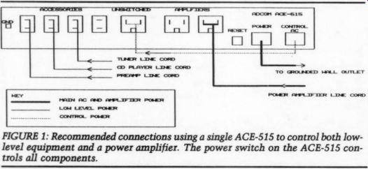
FIG. 1
The ACE-515 is a power-line filter that reduces RFI, EMI, and hash above 10kHz, with attenuation of 40dB at 150kHz. Ad com's unique L/C filter circuit is equally effective against transverse and common-mode noise. This is another way of saying the filter is equally effective in eliminating in-phase and out-of-phase noise components appearing across the hot and neutral sides of the AC line. The ACE-515 filters noise appearing between hot and neutral and hot to ground, as well as neutral to ground.
Adcom uses a proprietary double inductor called a ‘common-mode coil' as part of the filter. This coil is actually two coils wound on the same iron core, one for the hot side of the AC line and the other for the neutral side. The coils are wound in such a way their magnetic fields cancel at 60Hz, preventing the core from saturating at the line frequency.
The coils are wound with 13-gauge (AWG) wire, so they will not limit the current demands of power amplifiers. Of course, you must stay within the 10A (continuous) limit of the ACE-515's amplifier outlets.
The ACE-515 also provides fast-acting spike protection. (Adcom's claim is it re acts in less than ten billionths of a second.) Like the filtering, the spike protection is three-way, working from hot to neutral, hot to ground, and neutral to ground. For the ACE-515 to function properly as a filter and spike protector, you must use a properly grounded power outlet. This is important not only for the ACE-515, it is also essential if optimum performance from Adcom's new GFA 585 and GFA-565 power amplifiers is to be realized. These amplifiers are designed so the loudspeaker common and signal ground float relative to the chassis. The chassis is connected to the ground pin on the power cord, which must be grounded if these amplifiers are to perform with lowest possible distortion.
Many power outlets rely on the screws that hold them in the electrical box for the ground connection. (If your house has plastic electrical boxes, these comments do not apply.) The power-line ground wire is often connected to the metal electrical box, but not directly to the green ground screw on the outlet. This is fine for operating light bulbs, but it simply won't do for audio equipment requiring a real ground connection.
Have a licensed electrician check your power outlets and perform any necessary wiring. He can install a short 12AWG wire between the outlet box and the ground screw on the outlet. The electrician can also check to ensure the screw connecting the power-line ground wire to the outlet box is tight. Because of the safety and legal problems involved, Audio Amateur can't suggest you make changes to your house wiring yourselves.
Controlling Turn-On/Turn-Off
In addition to the power-line filtering and spike protection, the ACE-515 offers a unique method for controlling turn-on and turn-off of your audio components.
Two banks of switched outlets are con trolled by a pair of 10A internal relays.
Two grounded outlets are provided for power amplifiers and are rated for a total of 1.2kW, or 10A. Note that the 10A rating is continuous. These relays will carry peak currents in the hundreds of amperes, sufficient to handle the instantaneous current drawn by nearly any amplifier when power is first applied.
Adcom says the maximum power is 1.5kW, but the specs clearly state the maximum current for these outlets is 10A, the rating of the relay. Ohm's law prevails:
P =I x E = 10 x 120 = 1.2kW, still plenty for nearly any power amplifier. Four ungrounded outlets (labeled “accessories ”) are provided for low-level electronics, including a preamp, CD player, tuner, and other devices. A third, unswitched, grounded outlet is also provided. The maximum combined current capability of the four ungrounded outlets plus the unswitched outlet is 2.5A, or 300W.
The ACE-515 has two power cords.
One is a heavy, 14AWG grounded cord, which supplies power, via the relays, to the equipment. It is plugged directly into a grounded wall outlet. The other is an 18AWG ungrounded cord, which operates the relay control circuitry.
You can use the ACE-515 in several ways to control your components. I recommend using the ACE-515 power switch as the on-off switch for your en tire system (Fig. 1). In this case, the control cord is plugged into the unswitched outlet on the ACE-515. Your low-level electronics, including your preamp, CD player, and tuner, are plugged into the accessories outlets. Your power amplifier should be plugged into one of the grounded amplifier outlets. If it doesn't use a grounded power cord, don't worry about the ground.
When the ACE-515 is turned on, the low-level outlets are powered up immediately, but the power amp outlets are delayed by ten seconds. This allows enough time for all of your low-level electronics to stabilize before power is applied to your amplifiers, eliminating potentially damaging turn-on thumps.
When the ACE-515 is turned off, the power amp outlets are shut down immediately, but the low-level outlets re main powered for 30 seconds. This allows the amplifier time to discharge fully before the low-level electronics are shut down. A pair of LEDs on the front panel illuminate when power is applied to the outlets. [Many hardware stores sell a small outlet tester for $5 or so, which quickly tests whether the outlet is properly and safely wired. -Ed.
Since the actual power switching is done by the ACE-515's high-current relays, its power switch is not required to pass the high levels of current demanded by your power amp. The ACE 515 eliminates the need for manually switching your components individually and provides safe turn-on and turn-off sequencing for your entire system. All equipment plugged into the switched outlets of the ACE-515 must be left on.
You can connect the ACE-515 so the preamp power switch controls the sys tem switching.
In this case, the preamp power cord is connected to the unswitched outlet on the ACE-515, and the ACE-515 control cord is plugged into a switched power outlet on the preamp. This configuration has one disadvantage-the preamp is not affected by the turn-off sequencing. If your preamp has a built-in muting relay, this is of no consequence. If it doesn't, avoid this method and connect the ACE-515 as shown in Fig. 1. If your preamp doesn't have a power switch and you wish it left on all the time, plug it into the ACE-515's unswitched outlet and plug the control cord into any convenient wall outlet.
Testing the Equipment
When the ACE-515 arrived, I wasn't sure what to expect in terms of sonic improvement. I admit I was a bit skeptical regarding the unit's ability to help my situation. The worst problem with my system, on bad days, was a grundgy mid range, bordering on distortion with certain recordings. I wasn't convinced RFI filtering above 10kHz would have much effect on my dirty midrange. But, I had to try it to find out.
Before connecting the ACE-515 to my system, I hauled it over to Lorelei's. She and her husband live 15 miles south of Potsdam, out in the country (where they get that clean, all-natural country power, right?). She had mentioned in consistencies in the sound of her sys tem. She has a pair of Vandersteen 2Ci loudspeakers, one of Adcom's superb new GFA-585 power amplifiers, an Ad com GFP-565 preamp, and a POOGE-4 Plus modified Magnavox CDB-650 CD player. I told her not to get her hopes up, that I had no idea what effect the ACE-515 would have and that it might not do anything where she lived.
Her system had plenty of warm-up time before we started. We began by trying the ACE-515 on the preamp and CD player, leaving the power amp unfiltered. Our procedure involved playing a recording without the ACE-515, connecting the filter, and playing the recording again. We did not change any of the MAAD parameters. Our initial reaction was one of astonishment. The ACE-515 improved virtually every aspect of her system's performance.
The most immediately noticeable difference was a cleaner-sounding system.
It was as if a layer of dirt had been cleaned away in the midrange and treble. The sound was warmer and significantly more detailed. The soundstage expanded in width and depth, with greater precision of location. The bass extension was improved, and the bass had more clarity and impact (from a filter that doesn't have any effect below 10kHz).
The Vandersteen 2Ci's only bad point, considering their size and price, is a harshness in the upper midrange/lower treble region. This problem has been reduced by improvements Lorelei has made in her electronics. Changing power amps (she used to have an older Adcom GFA-545 amplifier) helped the situation considerably, but it didn't eliminate the problem. The ACE-515 made a substantial improvement here, also. In fact, Lorelei believed the ACE-515 had made as great an improvement in her system as changing power amps. I couldn't argue with her view.
When we removed the ACE-515, all the improvements disappeared, so we had no reservations about reconnecting the filter and adding the power amplifier.
The effect it had on the power amp was not nearly as dramatic. The most notice able improvement was in inner detail, with the other aspects of performance improved much more subtly. After one evening's listening, Lorelei decided to buy her own ACE-515 and has been delighted ever since (except during a re cent ice storm, when their power was out for three days).
I was now very excited at the possibility of trying the ACE-515 on my own sys tem. At home, I observed the same improvements, and to the same degree, that Thad heard on Lorelei's system. Over the past few months, my system has been much more consistent than before. The midrange grundge I've spoken about was normally at its worst in music where the instrumental scoring is very tight-the parts are very close together.
FIGURE 2: Recommended connections for three ACE-515s in a bi-amplified setup. A switched power outlet strip controls the entire system.
Tightly scored music for strings was a particular problem. One CD that hardly ever sounded right on my system was the Mercury Living Presence re-issue of Respighi's The Birds, a marvelous performance by Antal Dorati and the London Symphony Orchestra. Since I installed the ACE-515, this recording has never sounded less than acceptable, and most of the time it is very good indeed.
Multiple ACE-515s
After using a single ACE-515 in my sys tem, I decided to explore the possibilities of using multiple units. Several reasons for doing this are obvious. First, many audiophiles prefer long interconnects and short loudspeaker cables, which requires putting the power amp close to the speakers. In my own case, my system is usually multi-amplified. I prefer not having my power amps pulling current through the same ACE-515 coils feeding my pre amp, player, and electronic crossover. In either case, having separate ACE-515s dedicated to your power amplifier(s) isolates your low-level electronics from the current demands of your amps. The control capabilities of the ACE-515 allow you to switch power to your amplifiers remotely.
Figure 2 shows a connection scheme for operating a bi-amplified system using three ACE-515s, one for the low-level electronics, and one for each stereo power amplifier. In this configuration, the three control cords are fed to a switched power outlet strip. The outlet strip becomes the power switch for your entire system. Radio Shack makes a six outlet strip, #61-2619, which is ideal.
The price tag of $21.95 may seem high, considering True Value hardware stores often have six-outlet strips on sale for $9.99. But, Radio Shack's outlet strips are extremely well-built and housed in heavy aluminum cases, compared to the cheap plastic used in the $9.99 hardware store power strips.
Since the relay control circuitry draws only 250mA, you can safely add extension cords to the control power cords.
This allows you to put the power amps near the loudspeakers, while still con trolling turn-on and turn-off from a location near the rest of your equipment. I recommend 16AWG polarized extension cords for this purpose. The main power cords on the ACE-515s used for the power amps should be plugged into nearby grounded outlets. The power amps can then be connected to the grounded amplifier outlets on the ACE-515s. To avoid limitations on the current available to your power amps, never use extension cords on the amplifiers or the main ACE 515 power cords.
The ACE-515 used for the low-level electronics should be placed close by, eliminating the need for extension cords for any of these components. Again, plug the main power cord into a grounded wall outlet, preferably without using an ex tension cord. Even though none of your low-level components normally have grounded power cords, the ACE-515 still requires a grounded outlet for proper filtering and spike protection.
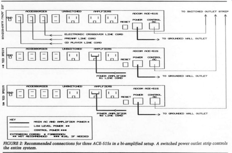
The connection scheme shown in Fig. 2 can be adapted for a variety of situations. You could use the two power amp filters for separate mono power amps (usually called “monoblocks ”; I don't know why-nobody calls stereo amps 'stereoblocks'). A tri-amplified system could employ four ACE-515s, which al lows a separate unit for each stereo power amplifier. If a fourth filter stretches the audio budget a bit too far, stick with three. Use one power amp filter on the woofer amp and the other for the mid range and tweeter amplifiers.
Some readers may have low-level equipment that takes longer than ten seconds to stabilize. ] have bypassed the out put muting circuitry on my highly modified CDB-650 compact disc player (the muting scheme raised the output impedance of the player). It takes about 15 seconds for the output DC offset to stabilize.
You can easily modify the timing circuitry that controls the power amp turn on delay. I increased the turn-on delay to nearly 30 seconds.
Two resistors in the left front corner of the PC board (as you face the front panel) must be changed to increase the delay. These resistors, R13 and R14, are connected in series; their factory values are 470k and 1M, ½ W. The ACE-515 ser vice manual suggests 1.8 and 2.7M for a 30-second delay. The exact values aren't critical, as long as the total resistance is close to 4.5M. Iused 3.3 and 1M because they were convenient. This gives a total resistance of 4.3M and a turn-on delay of 28 seconds. Adcom will sell you a service manual for $12, post paid. Since the low-level turn-off delay is factory set at 30 seconds, there's no need to change it.
Many power-line filters cost much more than Adcom's. The highly respected Tice Powerblock begins filtering much lower in the frequency spectrum than the Adcom, but it costs $1,250. Al though I don't have first-hand experience with the Tice device, people whose opinions I respect have spoken very favorably about it. In particular, Robert Harley's review in Stereophile is not only a rave, it is extremely informative reading for anyone interested in power-line filtering.2 The ACE-515 and the Tice Power block shouldn't be considered mutually exclusive. The Powerblock is intended to be left on all the time and offers no control capability. An ACE-515 or two could easily be plugged into a Powerblock, providing even more filtering and retaining the excellent system control offered by the Adcom product.

Words of Caution
Victor Campos tells me that some users have mentioned the ACE-515s make a buzzing noise when their power amps are turned on, concluding that their amplifiers have exceeded the current capabilities of the Adcom filter. This normally isn't the case. Buzzing can be caused by polarity reversal of the AC line. If your power outlets are wired so the hot and neutral lines are reversed, the ACE-515 may buzz, depending on what equipment is connected into it.
It is essential that all of your power outlets be polarized correctly. If you run extension cords for the control power, they must be polarized. Don't ever at tempt to reverse polarity by removing the ground pin on the main power cord or by filing down the wide neutral pin on the control cord so it can be turned around.
Doing either of these things to any electrical device is stupid and dangerous.
The control power supply on the ACE 515 has been idiot-proofed by the use of optical coupling to the control circuitry.
Defeating the unit's polarization won't make the ACE-515 unsafe, but the effect on other equipment plugged into the ACE-515 may create a hazardous situation. If you are uncertain about your house wiring, have a licensed electrician check it for you. In a properly wired building, the voltage between the wide, neutral pin and the ground pin should be less than 1V AC. If your house wiring is old and doesn't have polarized outlets, your electrician should change them.
It is also important to avoid ground loops, which can be caused by associated equipment having paths to ground different from the ACE-515. Cable TV and other antenna lines can be a particular problem. Always use a balun transformer to connect 75 ohm antenna lines to the 300 ohm input on your FM tuner. Never connect a cable TV or other antenna shield to the chassis of your tuner. In other words, don't use the 75 ohm input.
Most audiophiles and audio amateurs have ignored the effects of power-line noise. Victor's initial reaction to my glowing comments on his device were:
You must have a very dirty power line. After my experiences with the ACE-515, I conclude that most of us have dirty power lines-it's just a matter of degree.
I can't imagine anyone spending hundreds, or thousands, of dollars on high performance electronics or parts to build their own, without investing in power line filtering. If you don't, chances are you're not hearing why you invested all that time, effort, and expense in the rest of your equipment.
Victor Campos has another winner here. The Adcom filter will benefit many
more audiophiles than the city dwellers he had in mind when he designed it. The ACE-515 is an outstanding product that will improve the performance of nearly every high-resolution audio system. At $180, it is one of the most cost-effective improvements you can make to your system.
Adcom ACE-515 AC Enhancer. Adcom, 11 Elkins Rd., East Brunswick, NJ 08816, (201) 390-1130. Price: $180. Service manual: $12 postpaid.
REFERENCES
1. Galo, Gary, “Audio Concepts Sapphire II, ” SB 6/90, p. 56.
2. Harley, Robert, 'Tice Powerblock & Titan AC Conditioning System, ” Stereophile, April 1990.
AUDIO AIDS
ADAPTER FOR TESTING CABLE CAPACITANCE CABLE
CAPACITANCE IS NOT a subject discussed often, and manufacturers' specifications are seldom listed, but it is an important topic. Although many cables have a moderate amount of capacitance, around 100pF/meter, some have 300pF/ meter or more. The champion, as far as I am aware, is MIT's Shotgun CVT at 1,500pF/ meter. One meter of this cable exceeds the standard IHF capacitive loading of 1,000pF, which was designed several years ago as a worst-case load for testing purposes.
What does all of this mean? If, for ex ample, you built the Curcio Daniel pre amp or have an old Dyna FM-3 (both of which have an output impedance of about 5k), a 600pF load (cables plus power amp) will cause a 3dB rolloff at 50kHz. Assuming amp capacitance is negligible (not always true, especially if the amp incorporates an input high-frequency rolloff to protect it from TIM distortion), this 600pF load corresponds to 4-5 meters of Monster Cable, for ex ample, but only a foot and a half of the MIT Shotgun.
Perhaps you have decided to build a passive preamp for cleaner sound. Since you have a tube phono amp, you don't wish to load it down too far, so you plan to use a 100k-ohm volume control. The maximum output impedance of the volume control is R/4 at - 6dB or about 25k for our example, so a mere 150pF load would cause a 3dB rolloff at 50kHz. In this case, choice of cable could be critical and may result in marked differences in sound because of an inappropriate choice.
Most passive preamps use a volume control of around 10k to reduce the out put impedance and interconnect problems, at the expense of possible loading problems at the input end. Regardless of whether you use measurements or prefer to use the golden-ear approach to audio, you should avoid such obviously incompatible components.
Since capacitance specifications are not generally available and are rarely published in test reports (an exception is Martin Colloms' article in the June 1990 issue of Hi-Fi News & Record Review), you must measure them yourself. Some newer digital multimeters incorporate capacitance measurement functions.
Decent digital capacitance meters are quite inexpensive and useful to the amateur for matching capacitors for best channel-to-channel balance, as well as for selecting capacitors for frequency-de pendent networks, such as RIAA equalization. However, their alligator clip leads do not attach very securely to phono plugs, and lead movement in attaching the clips can cause variation of 10-20pF in the measurement. Although the latter is not a big problem, the lack of secure attachment can be annoying.
I solved this problem by building a simple adapter using a pair of banana plugs, about 5 ” of zip cord, and an in-line phono jack (Photo 1)-all parts available from Radio Shack. The phono jack accepts the cables securely and using the zip cord maintains the hot and ground leads in a fixed relationship to each other. This prevents variations in capacitance measurement due to relative movement of the two leads, and the banana jacks plug directly into the meter. Adapter capacitance is on the order of 10pF, which is easily nulled out at the meter.
This adapter is also useful with a multimeter for checking cables for short circuits between hot and ground leads. You can use it to adapt any test instrument with binding post inputs or outputs to use regular audio cables.
JAMES LIN Galveston, TX 77551
SHORTLY AFTER MY ARTICLE on building an antenna switchbox appeared in “Audio Aids ” (TAA 3/88, p. 46), Bill Ruck commented on the unsuitability of the design for FM and suggested a switchbox from Radio Shack would produce better results. (Interestingly, my design resulted due to the poor performance and short life I had experienced with using an earlier model of Radio Shack's antenna switchbox.) As the performance and reliability of my design have been very satisfactory, his comments prompted me to perform some tests, resulting in a small but effective modification.
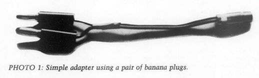
PHOTO 1: Simple adapter using a pair of banana plugs.
Mr. Ruck stated the change from 75 ohm coaxial cable to bare wire inside a chassis is an abrupt step change in impedance, which causes reflections. These, in turn, can cause ghosts in TV and multipath in FM. Actually, I used insulated (but not shielded) 16-gauge stranded copper wire for the internal wiring. This internal wiring may change the impedance, but performance has been very good.
These wires are 2-3 ” long, and are completely enclosed in an aluminum box, which provides some shielding of the wires from outside influences. Bulk head coax connectors conduct the signal between the coax cables and the internal wiring to and from the switch. When I measured the signal strength through the box and by bypassing it with a direct connection, I did not detect or measure any difference. I used a volt-ohmmeter and the signal strength meter on my tuner to measure and compare the signal strengths.
Mr. Ruck indicated inadequate isolation existed between inputs, so one antenna signal will lead to the other. By disconnecting one signal source at a time, while checking the signal strength, I identified a low level of internal cross talk. With that discovery, I made a minor modification.
I was able to remove the crosstalk completely by wrapping each of the internal wires in aluminum foil to shield them from one another. I purchased Radio Shack antenna switchbox number 15 1249 and compared its construction and performance to my design with the foil wrap added to the internal wiring. Both switchboxes appear to be equal in performance in terms of sound, measured signal strength, and isolation between signal sources.
The Radio Shack box has a central in put F connector and two pushbutton switches that are mechanically inter locked so only one at a time can connect the center input to either of two output F connectors. All parts are housed in an open-sided zinc casting, with a copper cover plate over the switch mechanism and a steel cover plate over the entire open side of the casting. The switch mechanism consists of a bare brass strip formed in the shape of a shallow U that is pushed into position so it spans be tween the central connector and the output connector. This appears to cause an impedance mismatch similar to that created by my design. The whole assembly is housed in a plastic box.
The past three years have shown my switchbox to be reliable. The current design of the Radio Shack box appears to have the same potential. It is certainly an improvement over the previous model. My assessment is that performance is equal between the two designs.
It then becomes a question of building one or buying an off-the-shelf model.
JAMES T. FRANE
Orinda, CA 94563
SHARING IDEAS
I ENJOY READING TAA. Your periodical re minds me of the French L'Audiophile.
I wish to share two ideas with you. The first is how to eliminate entirely the ad verse effects of loudspeaker cables. You don't need special cables-OFHC or any other type. Any simple wires will do, but use four conductors instead of two.
Any specialist in the field of test and measurement knows the four-terminal or four-wire resistance measuring principle. This is a tricky method for eliminating the resistance of the measuring cables when you are measuring low resistances--100 or below (Fig. 1). A calibrated known current generator forces a given current across the resistance to be measured, and a voltmeter measures the voltage drop across only the resistance, not involving the measuring cables. The voltmeter is connected to the unknown resistance through two separate cables and you can ignore the cur rent flowing through these cables. Similarly, the other two cables carrying the measuring current can be at any reason able impedance.
I use this method for interconnecting my amplifier and loudspeakers. The two original cables connect the amplifier output to my speakers, and the two extra cables bring back feedback signal from the loudspeaker terminals to the amplifier. This is not “motional ” feed back, but normal negative feedback.
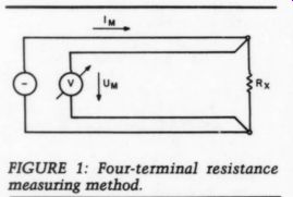
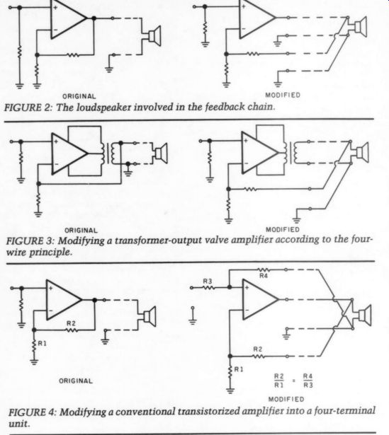
FIGURE 1: Four-terminal resistance measuring method.
FIGURE 2: The loudspeaker involved in the feedback chain.
FIGURE 3: Modifying a transformer-output valve amplifier according to the four wire principle.
FIGURE 4: Modifying a conventional transistorized amplifier into a four-terminal unit.
I separate the negative feedback components from the output of the amplifier and drive them with the signal from the other end of the loudspeaker cable.
The amplifier monitors and corrects the signals not at its own output, but at the loudspeaker terminals. In other words, the loudspeaker cable becomes a negative feedback chain. The original and the modified versions are shown in Fig. 2.
It is simple to implement this method in tube amplifiers as shown in Fig. 3, but a conventional transistor amplifier can also be modified according to Fig. 4. The effect of this modification is superb: the soundstages gain depth and width, the bass is tight, and the individual instruments are perfectly localized. This modification is worth a try since it costs al most nothing and you can gain a lot.
The second idea is a tube preamplifier I have been using for a couple of years.
Simple, but better than any other I have found, it is based on a series of articles in L'Audiophile. The SRPP (shunt regulated push-pull) Anzai (its inventor) is, in essence, the circuit proposed by Mr. Paul in his letter (TAA 2/85, p. 53). I have experimented quite a bit with this arrangement.
This is the most linear gain stage that can be built using tubes. Figure 5 shows the original version. Its transfer characteristic is symmetrical at its operating point because the current flowing through both resistors R drives the individual halves of tubes in the opposite sense (hence the name SRPP). The greater the drive voltage, the greater its distortion. It has a very natural, “soft-distortion ” characteristic, dominating the second harmonic product. No feedback is needed using this stage because its distortion is below 0.1% at V,,, = 1Vg,c using 12AX7.
Resistors R stabilize the current. The only disadvantage of this format is its relatively high output impedance. This shortcoming, however, can be eliminated with the modified version (Fig. 6) whose output impedance is reduced by a factor of ten or more depending on the circumstances.
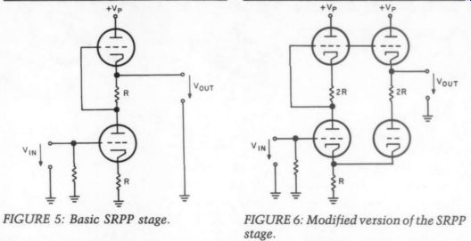
FIGURE 6: Modified version of the SRPP stage.
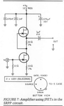
FIGURE 7: Amplifier using JFETs in the SRPP circuit.
The gain and output impedance are determined by the tube itself: R, V, have only a minor effect. Using 12AX7, V, = 330V and R = 1.2 k-ohm, the gain is 34dB, Zout = 31.5 k-ohm with the basic SRPP stage. With 6DJ8, these values are R = 820 ohm, gain = 24dB, Z,,, = 1.36 k-ohm.
I use a passive RIAA equalizing net work between a 12AX7 and 6DjJ8 stage, followed by a 6DJ8 line amplifier. The most important thing is a well-stabilized, rock-solid power supply because the SRPP stage is quite sensitive to power supply disturbances; its PSRR (power supply rejection ratio) is very low.
The SRPP principle is so good I've built a FET preamplifier for a moving coil cartridge using this schematic. Figure 7 is its circuit diagram. The devices are very special SILICONIX U231s: their I_ps is about 100mA. In this circuit, they run with 47-50mA and with very low noise.
Again, the well- stabilized power supply or even a car battery is advised for optimum results.
Also, the wiring is very important. The U231s should be thermally coupled be cause the operating point is sensitive to the thermal difference between the de vices. They should be electrically isolated because the gate is connected to the case. These devices were originally developed as an input stage in RF equipment in grounded-gate connection.
In my hi-fi system, this simple circuit out-performed the ORTOFON T-30 transformer, all of the transistor head amps to which I compared it, and even a similar SRPP tube head amp using 6DJ8, V, = 12V and R = 47 ohm. The difference is not significant between the tube and the FET version, but the latter is more detailed, more open, and quieter.
The final judgment is a matter of taste.
The FETs should be selected to equal I_DSS at V_DS = 6V and gate tied to source; the difference between them should be less than 2-3%.
SASZAR LASZLO
Budapest, Hungary
LETTERS
BALANCED AMP DEVICES
I wish to THANK Erno Borbely for an excellent discussion on balanced input and output circuits ( “Balanced Audio Amplifiers, ” TAA 1/91, p. 14), which was thorough and informative.
Readers should be aware that two new devices are now available from Analog Devices (PO Box 58020, Santa Clara, CA 95052-8020, (408) 727-9222, FAX (408) 727-550) that provide a simple, low-cost, and high-performance solution to differential line driving and receiving of audio signals (Fig. 1). The SSM-2142 Balanced Line Driver uses a cross-coupled topology, similar to Fig. 11 in Mr. Borbely's article, that provides a floating balanced output from single-ended sources. By using thin-film resistors and laser trimming, the SSM-2142 will handle difficult loads such as a 600 ohm termination at the other end of 500 feet of cable.
SHIELDED TWISTED-PAIR CABLE
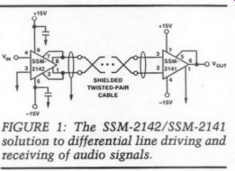
FIGURE 1: The SSM-2142/SSM-2141 solution to differential line driving and receiving of audio signals.
The SSM-2141 Differential Line Receiver provides a single-ended output from differential inputs, similar to Fig. 14 in the above referenced article. Also using thin-film resistors and laser trimming, typical CMRR is 100dB at 60Hz and 70dB at 20kHz.
Both devices are housed in 8-pin mini dip packages with no external components required, and are available from multiple distribution locations including Newark, Allied, Hallmark, Anthem, _ and Bell. In single quantities, the SSM 2142 is priced at $4.43 and the SSM 2141 at $2.93. The SSM-2016, also mentioned in the article, sells for $6.98. Finally, the SSM Audio Products Audio Handbook, containing 25 datasheets and 19 application notes, is available free from any Analog Devices sales office.
However, be sure to ask for the final SSM-2142 data sheet, as the handbook has only a one-page advanced information sheet.
If there is any confusion, Solid State Micro Technology for Music (SSM) was acquired by Precision Monolithics (PMI) in 1988, which was in turn acquired by Analog Devices in 1990. Whew! The SSM line, now combined with audio converters, makes Analog Devices a strong contender in high-performance audio integrated circuits.
DAN PARKS SSM
Audio Products
SONIC THUMBPRINT
I THINK I CAN add to Johannes Didden's letter about Jim Bongiorno's amp ('On Capacitors and Bridges,' TAA 2/88, p. 53.) In Mr. Bongiorno's original article (4/84, p. 7) he says electrolytics are imperfect devices but a designer has no realistic alternatives for filtering high current power supplies.
Mr. Didden contends that the amplifier's power supply rejection ratio (PSRR) would neutralize distortion that these imperfections cause. I would agree that the amp's PSRR certainly would reduce the audibility of the power supply's ripple but my experience has been that the overall sonic thumbprint of electrolytics remains.
In a split supply, single-ended amp, each half of the circuit works between the load and the power supply capacitors.
If a step is put through this stage, each cap will have to supply most of the instantaneously required current. These capacitors are completely outside of the amplifier's feedback loop (Fig. 1).
FEEDBACK
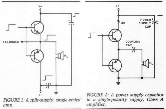
FIGURE 1: A split-supply, single-ended amp. FIGURE 2: A power supply capacitor in a single-polarity supply, Class A amplifier.
One might think that a Class A amp would negate this effect. Indeed some one monitoring the power drawn through the line connection would find that the ideal Class A amp draws the same power whether idling or driving a load. However as Mr. Boak points out in his 1/80 article (p. 6) concerning the Pass A40--The reason for regulation is that Pass has chosen a bipolar push-pull design.
With three current paths and a full load current much greater than the idle current, the amp looks like a Class B load (plus a constant) to the power supply. Interestingly, the power supply capacitor in a single polarity supply Class A amplifier does not have this drawback.
As a step into this stage, the N-channel transistor conducts more and the P channel transistor conducts less and as long as neither is driven to cutoff, the power supply only “sees ” the idle power.
The music power is subtracted from the idle power. The power supply capacitor does not have to deliver a step of current.
However, now the coupling cap must transmit the step (Fig. 2). In some cases you can parallel large polypropylene caps for this job. I've built two sonically successful guitar amps using three 80uF polypropylene caps here. They are nearer than any electrolytic I've tried. 240nF doesn't sound like enough capacitance, but it works fine in this application. I use a 16 ohm musical instrument loudspeaker whose impedance rises at lower frequencies. Also a guitar's lowest fundamental is only about 82Hz.
This technique is expensive and not practical for most hi-fi applications.
What kind of output circuit would be a constant load for the power supply caps and not have a coupling cap? I asked St. Pooge and he answered: 'A Class A bridge circuit with the like polarity transistors connected to a common power supply cap ” (Fig. 3).
As the left side N-channel transistor is turning on, the right side N-channel transistor is turning off. Since this is a Class A circuit and these two transistors are connected at the collector, the sup ply capacitor doesn't have to deliver a step of current. This minimizes the un musical nature of electrolytics. This same operation, of course, occurs in opposite phase with the P-channel pair.
Needless to say, the coupling capacitor problem has disappeared.
If any of you wish to build this kind of circuit, be sure to choose your operating conditions carefully. Because each side of the load is driven with signals of opposite phase, the effective load resistance is halved (see “Bridging Baffles, ” TAA 1/81, p. 50, Walt Jung's reply).
If St. Pooge is right, then people who are bridging stereo amps with separate supplies for each channel (like a Pass A40) should get improvement at lower power levels simply by connecting the like polarity power supply capacitors of each channel.
RICK BERGMAN
Medford, OR 97504
Johannes Didden replies:
Your comments are to the point and I can only agree to them. But let's not forget why we have trouble with those filter caps: their imperfect behavior causes an AC component to appear on the DC sup ply voltages. This component is dependent on frequency, output power, amp topology and, last but not least, the quality of the supply and its caps as a whole.
This AC component may insert distortion products into the output signal, especially through the pre-stages. These are particularly vulnerable because here we often find voltage-and current sources referenced to the supply lines. Some times even signals are coupled from one stage to the other using the supply as a “common. ” Trying to minimize the supply anomalies by using a bridge configuration is one possible avenue; I would agree that using a separate supply for the pre-stage offers better results for less effort and less cost.
Bridge configurations have their own disadvantages and are much costlier.
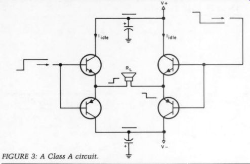
FIGURE 3: A Class A circuit.
I guess my original comment was triggered because I got the impression a bridge circuit was presented as a cure-all, which it definitely is not.
CD GROUP DELAY
I READ YOUR guest editorial, “Catch Penny CD, ” in TAA 3/89 with interest. I believe that Keith Armstrong does not go quite far enough in stating how the group delay correction should be achieved in the recording chain. He is certainly correct in stating the essential operations that should be performed immediately one after the other:
1. An anti-aliasing filter that attenuates all frequencies beyond the folding frequency a very large amount does not affect the amplitude of frequency components of the signal very much and has a known phase response.
2. A high quality A/D converter.
3. A phase correction filter that establishes a linear phase versus frequency relationship corresponding to a constant time delay versus frequency.
What he does not say is this must be a digital filter, because we wish to do as little analog processing ahead of the A/D converter as possible, and once converted, the signal should never be reconverted to analog until the user's CD player. Also, only a digital filter can per form perfect correction since the amplitude and phase response can be set in dependently. An analog filter can only do this approximately, approaching perfection as the number of circuit elements approaches infinity.
This would have been an extremely expensive standard in 1980; it would have been practical for only a small fraction of the recording industry. But this is no longer the case. The best way to do this filtering is with frequency do main convolution. The signal is transformed with an FFT (fast Fourier trans form) integrated circuit; the resulting signal is multiplied by a set of filter coefficients stored in a ROM (read only memory), and then retransformed with another FFT circuit. This circuit could be mass-produced for somewhat more than the cost of a good A/D converter.
In 1980 it would have cost about $50,000 and would have occupied a significant part of a rack. Now the FFT chip has come of age. Soon a chip will be introduced that can keep up with a 10MHz rate, which makes audio seem trivial.
However, it is not really trivial; audio needs the full 16 bits and not all FFT chips can handle this at the input. Also, there are other technical problems; for example, the output must look like that of the A/D converter, so the filter can be put just after it without making any changes in the rest of the system.
Ideally, the analog filter, the A/D converter, and the digital correction filter should be sold as a unit. In this way the manufacturer can establish the correct filter coefficients. Also, the design of an analog filter would be easier if it were followed by a digital correction filter.
For example, the amplitude of the spectrum can be corrected also, just by taking it into account in the digital filter coefficients. This costs no more in the digital filter, but could make the analog filter simpler since small ripples in the amplitude of the frequency response could be corrected.
One expects a lot of inertia in any industry, but improvements in digital processing have left much of the recording industry way behind. This is easily corrected, and anybody in a position with any influence should see that it is done.
MICHAEL P. SULZER
Arecibo, PR 00613
Keith Armstrong replies:
You make some interesting and important points. However, your proposal of a frequency domain convolution method for the phase-correcting filter, although elegant, may never find wide application in audio analog-to-digital (A/D) conversion because it requires massive processing power.
I recently led a project that employs a parallel processor of 16 T800s (floating point transputers each capable of 10 Mips) to do frequency domain convolution on 16-bit data at 4kHz sample rate.
They could only just manage this in real time. To cope with audio would require more than ten times as many-a rack of circuit boards costing over $20,000 at to day's prices just for the chips.
Custom-made processors would be much cheaper and are being designed for radar signal processing. These use fewer bits than audio, which requires 32-bit processing to avoid roundoff and truncation errors within the filter itself.
Whether anyone will design such a chip for the relatively small and price-sensitive audio industry remains to be seen.
Very real progress is, however, being made in A/D converters that will over come our current problems with the phase distortion in their anti-aliasing filters.
Several companies are bringing over sampling techniques (already common in audio D/A converters) to A/D converters. Very high sampling rates (over 1MHz) will require only RFI filters in the analog domain, and the decimation filters which follow in the digital do main to produce the 16 bits and 44.1 or 48kHz can be designed to be linear phase. Here we are in the hands of the semiconductor industry, and companies such as Crystal Semiconductor and Analog Devices spring to mind as pioneers in this field.
By the time the semiconductor industry has produced these marvelous A/D converters, and equipment manufacturers have designed them into gear that studios can afford to purchase, recordists will be able to swap from analog to digital and back to analog again as often as they like and quality will not be impaired by the converters.
On a parallel track, though, engineers are designing all-digital audio gear. The art of all-digital processing (as opposed to the science) may take a while to be come established, but when it does we shall be able to go digital from the mike amp to the power amp (or even the speaker itself) and our ears will be in heaven.
ADAPTED REGULATOR
I WISH TO ENCOURAGE readers evaluating candidate voltage regulator circuits to pick Mr. Ryan's original design, or an other proven design, in light of the following observations.
Although my adapted regulator driver boards and Motorola power Darlingtons ( “Letters, ” TAA 2/90, p. 65) are stable when driving their own dummy loads, they show a 75mV p-p high-frequency oscillation while driving a functioning power amplifier. Also, the closed-loop output impedance of this adaptation is too high to put real punch in the low frequencies. The regulator does indeed regulate and reduce most forms of distortion, resulting in superb imaging, but cannot otherwise be considered a successful adaptation, due to the faults presented above.
---------------
------------------
Overcoming these problems is the crux of good regulator design. I face the classic question of gain versus stability and am learning and testing stabilization techniques from practical and topological standpoints as time allows. To date, increased gain has improved regulation, but I have not solved the oscillation question. Surely many readers have “already been there. ” In conclusion, this experiment has proven to me beyond any doubt the necessity of regulated supplies for quality sound from stereo amplifiers. I continue my tests on this adaptation as a challenging learning experience. Meanwhile, there doubtless are readers with better qualifications than mine who can per haps field proven corrections or can offer their own successful high-power regulator circuits as has Mr. Ryan, whom I thank for stimulating my own interest.
Readers?
DARCY E. STAGGS
Orange, CA 92669
SSR PROBLEMS
I BUILT STEPHEN NITIKMAN'S “Sequenced Power On/Off Switch” from the 2/88 issue of Audio Amateur (p. 34). I use all four outputs to turn the preamp and three power amplifiers on and off in sequence and the circuit works perfectly.
However, as this was my first exposure to the use of solid-state relays (SSRs), I was surprised by one of their apparent characteristics. When they turn off, they are not completely off. I used the Crydom brand relays mentioned in the article, but instead of using the 2A and 10A (TD1210) versions as Mr. Nitikman did, I substituted the higher current 25A version (TD1225) because it was only slightly more expensive and I assumed more rugged. I use the relays to switch a Hafler DH-110 preamp, an Adcom 555, and two Hafler 500s.
I say SSRs do not switch completely “'off ” because when testing the finished circuit, I noted the Hafler DH-110 pre amp “power on ” LED did not go out when the relay was off. This was true regardless of which relay the preamp was connected to. Also, with no load on any of the relay outputs, I measured 120V at each output when it was off. I had an other interesting observation when I plugged an analog clock radio into an out let: the radio switched off when the relay did, but the clock continued to run. How ever, if the clock was unplugged and then plugged back in, it did not start running again.
I assumed that there must be a small amount of “leakage ” from an SSR when it is turned off, which may be load de pendent. I also assume this presents no problem to the power supplies of the devices connected to the relays and in fact may help keep power supply capacitors “formed. ”“' Does this phenomenon exist only be cause I selected oversized relays? Should some type of load resistor be connected to the output? Does a shock hazard exist? I am also curious to know how much isolation these devices provide, if any, from RFI, voltage transients, and AC line noise.
I wish to emphasize I am satisfied with the operation of the sequencing circuit.
The convenience of a single-turn on/off switch, thump-less zero-voltage switching, and reduced wear and tear on the pre amp and amplifier power switches make this a highly recommended project.
ANDY PARKER
Lancaster, PA 17601
Stephen Nitikman replies:
Thank you for building my sequenced power on/off switch. I always appreciate hearing from readers who find my projects useful. I will limit my discussion of SSRs to the problem you encountered with their use.
Silicon controlled rectifiers (SCRs) and triacs belong to the thyristor family of semiconductors and these are the work horses contained in AC SSRs, which switch power to the load. Various texts on device theory state that large SCRs and triacs will exhibit higher leakage cur rent (current passed when the device is in the “off” condition) than their smaller counterparts, and the same can probably be expected of their use in SSRs when comparing current ratings. Understand that for all practical purposes, a thyristor in the off state is an open circuit and device leakage should be negligible.
Since SSRs show some small leakage current, a modern FET input meter will probably see the full AC line voltage across the controlled outlet under no load conditions, whether or not the SSR has been triggered. This is normal.
Since all the 25A units you tested showed identical behavior under light loading, it is probably safe to assume this model SSR is not defective, but exhibits too much leakage for applications involving light loads. The internal snubber net work to the SSR may also be causing the problem you discuss. Leakage current in an SSR that causes any noticeable effect in the load should be considered undesirable. The 10A SSR in my prototype sequencer will not pass enough current in the off state to operate a clock, timer, or any other low-current household item under test.
If the SSR leakage encountered is resistive, you can connect a load resistor across the preamplifier outlet in hopes of negating the effects of unwanted leak age current. Remember that the resistor will be dissipating power in the form of heat and should be conservatively rated.
Start with a 5 k-ohm, 5W resistor (approximately 3W dissipated at 120V). Keep in mind that no load resistor should be required when using SSRs. I appreciate the expense incurred by this SSR, but you are better off selecting a smaller one for control of your DH-110 preamplifier.
It is doubtful that this problem constitutes a shock hazard. SSRs show no significant immunity to external AC line noise. The noise-reducing mechanisms inside SSRs (zero voltage switching and the snubber networks) are used to minimize switching-induced disturbances caused by thyristor switching within the SSR.
It is unfortunate that your first contact with SSRs gave you problems. If your expenses allow, try using a lower current model in place of the one set aside for preamplifier control duty. For all practical purposes, SSRs behave like standard power control relays; however, they offer a level of input range, sensitivity, output control, longevity, and compactness unmatched by their electromechanical counterparts. DC SSRs using FET switches are now available, but at very high cost. I hope this information will help you.
RESONANCE SOLUTION
DAVID PONTA COMPLAINS of resonance problems with his CDs ( 'Letters,' TAA 3/90, p. 58), which are particularly noticeable on classical piano recordings.
Since he can locate the phenomenon as mainly centered in the 500Hz area, I am certain it is one I am only too familiar with: resonance in the pressed steel case.
I am indebted to a 1987 article by J.P. Moncrieff in his IAR Hotline 46/47 ( PO Box 4271, Berkeley, CA 94704) for my approach to the problem. Also, a simple solution is one recommended by Gerald Burt (TAA 3/89, p. 60): place one or more large, heavy books on top of the player.
Alternately, you can use bricks resting on a layer of thin felt. Amore radical approach is to remove the metal sleeve.
This, though, allows sound waves-and particularly the sharp transient of piano recordings-to excite the transport and electronics directly; it also lets in dust.
I have tried acrylic, polycarbonate, and perforated cardboard lids. Each passed its own characteristic sound to the speakers, but found the last the most natural. An elegant solution that also adds mass is to have a stonemason cut you a piece of slate an inch wider than the case but an inch shallower. This rests on the sides of the box, while the space at the back ventilates the regulators.
Experiment with felt or bituminous pads between the slate and the case for the best damping. Bituminous pads on other outer surfaces of the case bring further improvements at the cost of elegance. Try the front of the loading drawer first.
All electronics are likely to be excited by piano transients. My Counterpoint SA12 amplifier had a top plate that rang at around 600Hz. Slate has finally fixed that. Heatsinks almost always ring if you run your fingernail across the fins, and they often color the output. The old Robertson 4010 had sheet metal heat sinks that gave a baritone rather than a trebel ring, and everyone said how warm it sounded. Making heatsinks with a fourth side linking the fins helps, and Philips now uses these in their CD players. I sometimes wonder if the current enthusiasm for tube amplifiers is due to the fact that they have no heatsinks and the metalwork is effectively damped by the heavy transformers.
DAVID FOXON
Marston, Oxford OX3 ORZ England
SCA-80Q MODS
IT WAS A PLEASURE to read Victor Staggs' ideas for bringing Dynaco's venerable SCA-80Q up to date ('Audio Aids,’ TAA 3/90, p. 47). In addition to his fixes, I recommend two other changes that slightly improve the amp's performance and make it a more useful device for today's audio systems.
The first change improves the accuracy of the phono equalization. The stock circuit's output is 0.5 dB low between 500Hz and 2.1kHz and 0.25 dB high above 2.1kHz. I recommend changing both RIAA EQ resistors to XW, 1% metal film types. R29 changes from 4.7k to 4.8k; R30 changes from 56k to 56.2k.
These values shift the RIAA zero from 308uS to a near perfect 318.2uS and the high-frequency pole from 70.5uS to 73uS. This change flattens the midrange dip, which makes the slight rise at the top less noticeable.
The second change revises the wiring of the special and phono inputs. In a stock SCA-80Q, signals from these in puts pass through the selector switch (SS) three times. SS lugs 6 and 7 route the selected signal through SS lug 5 to the phono preamp's input. SS lugs 3 and 4 select one of two feedback equalization networks. The standard wiring con figures phono and special as RIAA in puts; optional connections (and added components on the PC-17 boards) allow the special input to provide NAB tape head or non-RIAA phono equalization.
The output of the phono preamp is connected to SS lug 2, which feeds the switch outputs at lugs 1, 11, and 12 when the switch is in the phono or special position.
If you wish for your SCA-80Q to have two RIAA phono inputs, you can remove one set of contacts from the signal path by detaching C14 from SS lugs 3 and 4 and connecting it directly to PC-17 eye let 5. Use insulating sleeving on the lead to prevent a short to power or ground.
It is also possible to rewire the special input as a high-level input. I have in stalled a similar change in my PAT-5 preamp, with excellent results. Be careful when you rewire the selector switch, as this part is no longer available.
Begin by revising the grounding of the special input. Unsolder C13 from short lug 1-2, carefully bend up the ground shell tabs on jack 2, and remove the ground shell from the phenolic strip. If the short lugs on jacks 1 and 2 are soldered together, you may have to heat them to get the jack shell out. Turn the jack shell 180°, re-insert it in the phenolic strip, and bend the tabs back down.
The short lug from jack 2 should now be between jacks 2 and 3. Run a short wire between this lug and short lug 3-4 and solder it at both ends. Reattach C13 to short lug 1-2. Repeat the above steps for the right channel (jack 8).
Next, revise the selector switch wiring, one channel at a time. All connectors to this switch are made to both the front and back contacts of each lug.
Detach C14 from SS lugs 3 and 4.
Slip a piece of insulating sleeving on the free lead and connect it to PC-17 eyelet
Remove any wire stubs connecting SS lug 3 to SS lug 4.
Remove the wire from SS lug 5 to PC-17 eyelet 1.
Detach the wire from SS lug 7 and connect it to PC-17 eyelet 1. This routes the phono signal directly to the phono preamp.
Detach the wire from SS lug 2 and connect it to SS lug 4.
Detach the wire from SS lug 6 and connect it to SS lug 3.
Strip 0.25 “ of insulation from the end of a wire. Insert the stripped end through the front and back contacts of SS lug 2.
Solder the wire to both contacts and cut off the excess. This step ensures a positive connection between the front and back contacts.
Repeat the above steps for the second channel.
The revised wiring uses SS lugs 3 and 4 to select between the phono preamp's output and the high-level special input.
These signals pass through two sets of selector switch contacts on their way to the tape output and line stage. Notice that the phono signal is amplified and equalized before it is switched. In my experience, this arrangement minimizes switching transients and causes less switch-related signal degradation than the standard low-level switching.
DONALD P. BILGER
Livonia, MI 48154
Victor Staggs replies:
Your changes to the Dyna SCA-80Q seem to be in the spirit of adapting the product to the user's needs, to which Dynaco products are uniquely suited. I could only guess at the sonic changes due to amplifying the phono input before applying it to the selector switch. I have noticed such a large effect when changing to Teflon-insulated hookup wire that I often wonder whether sonic effects thought to be caused by switching arrangements are really due to the quality and length of the wiring.
Some audiophiles change to metal film resistors to remove a claimed smearing
due to the carbon resistors. Whether this is audible through electrolytic capacitors I cannot say for certain, but at least the resistor values will match more closely between channels.
If you have measured your phono preamp gain through an accurate inverse RIAA network, where the preamp is presented with a source impedance typical of a phono cartridge (resistance, series inductance, and shunt capacitance), then your RIAA time constant changes make sense. Otherwise, their effect will be smaller than changes due simply to substituting a different cartridge, for in stance. Calculating time constants only from the circuit values in the RIAA loop will not quite predict circuit performance because of the nonzero output impedance of the RIAA stage and its non-infinite input impedance.
A major improvement to the sound of the SCA-80 could be made by using active regulation for the line stage or the phono stage. These could by LM317T circuits that include a soft-start transistor (2N2907A) as per the National Semiconductor diagram, to avoid a punishing turn-on thump. I have added regulation to the PAT-4 without the soft-start feature, and the sonic benefits are great. The turn-on thump is also great. This is a good project for the careful experimenter.
REMEMBER SOUND GUARD
AFTER I READ “CD Lens Cleaning ” in Ask TAA (3/90, p. 49), I was concerned about the comment 'Never be the first kid on your block...(remember Sound Guard). On the recommendation of a fellow engineer at work, I had ordered several bottles of the last Sound Guard available.
Now I am worried. Have I destroyed my valuable LPs on which I used Sound Guard?
EARL BIXBY
Farmington, NY 14425
Contributing Editor Gary Galo replies:
It is unclear whether you used “Last ” brand record preservative or “Sound Guard.” I heartily recommend Last, but not Sound Guard.
Sound Guard left a film in the grooves, which softened inner details and, in time, actually made LPs noisier. Your records certainly aren't ruined, but I believe you are better off without Sound Guard.
FUSES AND MOVs MR. MASTEL'S Power Pro circuit (TAA 3/90, p. 26) is an effective method of combating surge and conducted noise problems on incoming power lines. I wish to suggest a change that will aid in the safety of the unit, however. Add 1A fuses in series with the metal oxide varistors (MOVs) and an LED. The latter is an indicator light that will go out if either fuse opens. The 1M resistor will limit current through the LED to a safe level (Fig. 1).
FIGURE 1: Adding fuses and a LED to the Power Pro.
Why? The MOV is a semiconductor device whose resistance decreases with increasing voltage. This action is what clamps spikes. By this definition, it is theoretically possible to apply enough voltage to drop the resistance of the MOV to 0 ohm, shorting the AC lines. In reality, this never happens. As the voltage is increased, the resistance of the MOV drops, the current through the MOV increases generating heat, and a thermal runaway condition is obtained burning up the MOV. This is true only if the energy of the spike on the power line is greater than the MOV's energy dissipation rating.
By placing a fuse in series with the MOV, you can stop the runaway condition before a catastrophic failure takes place. Mount the LED on the panel of the cabinet where you can see it. If the LED goes out, replace the open fuse and the MOV in series with it. The MOV has been stressed and can no longer be trusted to perform correctly.
UL Standard 588 states that a MOV will be within 10% of its clamping volt age and energy dissipation rating (joules) using the standard 8 x 20uS applied pulse. Unfortunately, a passing thunder storm will inject orders of magnitude more energy into the power lines than UL can ever dream of.
I have seen numerous surge protection products that looked like a bomb went off inside them when the MOVs be come overloaded. Install the fuses. With out protection, the MOV is a fire hazard and not a useful tool for protecting valuable equipment. By adding the fuses, the unit's safety is increased.
MICHAEL J. GERGEN
Mound, MN 55364
Vern L. Mastel replies:
You are absolutely correct. The Power Pro should have fused MOVs. The irony of your letter is that I was aware of the potential for failure of a MOV when I designed the circuit. The simple step of including the fuses never occurred to me.
I guess sometimes you cannot see the forest for the trees.
DYNA FM-7 MODS
THIS IS IN CONNECTION with Benjamin Poehland's article on modifications to the Dyna FM-3 in TAA 4/86 (p. 26) and David Berning's follow-up letter in TAA 2/88 (p. 51). I acquired an FM-3, re-tubed it, beefed up the power-supply capacitors, changed out the resistors and coupling caps, replaced the packaged electronic circuits (PEC), and realigned it.
I wish to confirm Mr. Berning's findings regarding the values of the PEC (part #555001). At first, I simply replaced the PEC with discrete parts, sized per the Dyna manual. As Ben Poehland stated, the sound was a bit bright. Changing out the parts in accordance with Mr. Berning's recommendations fixed everything.
The resulting unit sounds smooth and non-fatiguing; I listen to it in my office all day without any irritation. I wouldn't rave about the overload and selectivity of my particular sample, though. My Ad com GFT 1A worked fine with just a folded dipole. The Dyna didn't work acceptably until hooked it to my cable TV link. After that, it played perfectly. This may be a quirk in my unit.
The rest of the system consists of a POOGE'd Dyna SCA-35 and a pair of slightly modified Dyna A25 loudspeakers. I've heard worse.
LES WINTER
New York, NY 10003
Benjamin Poehland replies:
I did a listening evaluation of the three FM-3 de-emphasis circuits, and I heartily concur with Les Winter's observations. My test system was similar to his, consisting of a stock SCA-35 driving BIC Formula 1 speakers (Z = 612). All of my listening was done through Philadelphia's classical music station, WFLN (95.7).
The original de-emphasis circuit (Fig.
1) in a stock FM-3 yields what many people regard as classic tube sound: tubby bass, a rather indistinct midrange, and a soft rolled-off high end. The sound is not offensive, but could be likened to a comfortable pair of worn-out shoes that won't stay on your feet.
The circuit in Fig. 2, the one provided incorrectly in the Dynaco manual, yields a definite sonic improvement in my modified FM-3. Bass is tight and smooth, and midrange presence is improved. The high end is a bit bright and has too much air.
Some people like this sound since it resembles bipolar transistor tuners. You can tame the excessive airiness and treble brilliance somewhat by reducing treble gain, but this upsets the midrange-treble tonal balance and is less than satisfactory. However, the circuit really brings out the timbre of massed strings and wind instruments, as well as nuances such as the edge tones of organ pipes and flutes.
Dave Berning's circuit (Fig. 3) maintains all the best features of Fig. 2 in the modified FM-3, and in addition restores the overall tonal balance to produce the most comfortable, natural sound. I use the Berning circuit in my modified FM-3, and like Les, I never grow tired of it.
I've had perhaps half a dozen FM-1s, “FM-2s,“ and FM-3s on my bench over the past ten years, and they vary some what in their front-end performance.
(FM-2 was the unofficial designation for an FM-1 upgraded to stereo by addition of the FM-X3 multiplex adapter; the PC-8 IF strip is different in an FM-3 than in an FM- 2.) An FM-3 with poor overload and selectivity is either poorly tweaked, has a defective IF transformer, or a weak tube on PC-7 or PC-8. Sensitivity is greatly affected by the condition of the 6BAG6 IF stages. As the two 6BAG6 tubes (V3, V4) age, less current is drawn through R11 or R13; sensitivity and S/N suffer. Poor S/N and excessively high voltage at pin 6 of V3 or V4 indicate a weak tube or defects in R11/R13, C14-16, or T2.
I suspect the mediocre front-end performance mentioned by Mr. Winter is peculiar to his unit. My modified FM-3 has performed well, although I do use a Radio Shack 15-1122 booster with + 18dB gain. This has worked well for receiving fringe stations; for stronger stations, my modified FM-3 appears to have no problem absorbing the overload.
Upon opening my modified FM-3 to in stall the Berning upgrade, I was discouraged to observe further degradation of the circuit board in the vicinity of R11/R13 and that my metal-film resistors were cooked. The values of these resistors had shifted slightly upward, barely within tolerance. I decided to quit monkeying with these resistors and replaced them with 10.1k ohm, 5W, 1% mil-spec units (from Hanifin). I mounted the new resistors 0.5 ” above the board.
FIGURE 1: The original de-emphasis system.
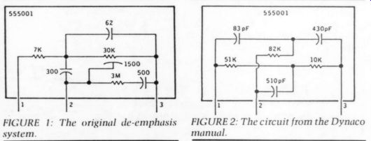
FIGURE 2: The circuit from the Dynaco manual.
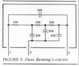
FIGURE 3: Dave Berning's circuit.
In my original article, I speculated whether conversion of filaments to DC would further improve the FM-3's sound.
Since I had my unit open, I tried it. It doesn't work. The power transformer's filament winding is already close to its output current limit, and additional dissipation through a full-wave bridge rectifier dropped the DC filament potential to about +5.5V. My FM-3 appeared to function at this voltage, but I abandoned the idea out of concern for tube life. Total filament current is around 2A, which re quires at least 20,000uF for decent filtration. There just isn't space in the FM-3 chassis for that much capacitance. Conversion to DC filaments will require an outboard supply. I'm fussy about the appearance of my gear and wasn't willing to carve up the sheet metal on my FM-3 to explore this further.
JUST LOOKING
Optoelectronics has announced a new type of universal frequency counter timer in the form of a 9 ” drop-in card for personal and laptop computers. The PC-10 uses Windows 3.0 as a control panel and display window and it directly tunes radio receivers such as the ICOM R7000, resulting in a uniquely configured self-tuning radio.
At the heart of the PC-10 are a 200MHz custom CMOS ASIC and three bipolar MMICs. It is a 10Hz to 2.4GHz radio instrument that measures, captures, and analyzes discrete and average frequency readings, pulse width, time interval, period, and the ratio between two frequencies. The PC-10 provides a 'reciprocal counting ” feature for eight-digit resolution of low-frequency readings.
The unit is simple to install, set up, and use. It works on an 8088 or higher based IBM-compatible PC with Windows 3.0. This frequency counter offers a software-calibration feature: input any reference signal and enter its frequency.
PC-10 determines the reference frequency, compares it to what you say it is, then writes the difference to an initialization file. Then, whenever PC-10 takes a measurement, it automatically corrects the reading according to the calibration data.
The PC-10 sells for $335 in unit quantities. For more information, contact Optoelectronics Inc., 5821 NE 14th Ave., Fort Lauderdale, FL 33334, (800) 327 5912 or (305) 771-2050, FAX (305) 771 2052.
Due to increased requests for refills of kit parts, surface mount resistors and capacitors are now available from Communications Specialists in small quantities and in individual values.
The unit of sale is per strip and each is clearly marked with the value. Resistors are furnished in strips of ten and sell % for $2.50/strip. Capacitors are furnished in strips of five and sell for $1.25/strip. The minimum order is $10. MC, Visa, COD, or prepayment accepted.
For a brochure, contact Communications Specialists, Inc., 426 W. Taft Ave., Orange, CA 92665-4296, (714) 998-3021 or (800) 854-0547, FAX (714) 974-3420.
Bang & Olufsen has introduced the Beosystem 2500, a compact, 14 ” high by 33 ” wide audio system with an art moderne architectural design. The central system houses the CD player, LCD dis play, FM-AM radio, and cassette recorder. Four amplifiers are integrated in to speakers (detachable) at each side of the central unit, and rear hand grips make it easy to move the system.
The 2500 offers numerous options for expansion or integration into a Bang & Olufsen whole-house audio/video sys tem. It comes with a handheld remote control, the Beolink 5000, which controls normal system functions as well as allows programming of timer recording or play. A liquid-crystal display window at the top of the remote confirms user commands and shows current system operating status. Two-way infrared signals enable the Beosystem 2500 and Beolink 5000 to communicate with each other.
The cost of the Beosystem 2500 with the Beolink 5000 is $3,500. For more in formation, contact Bang & Olufsen of America, Inc., 1150 Freehanville Dr., Mt. Prospect, IL 60056, (800) 323-0378.
MIT has introduced a metallized version of its MultiCap capacitor, designed for use in audio products to eliminate the distortions to music caused by parasitics in capacitors.
The metallized MultiCap is recommended for low-current applications such as preamps, amps, and electronic circuits. They offer the same precision in design and construction, the same pa tented coaxial structure, and the same sonics found in the film-and-foil Multi Cap. Each unit contains multiple paralleled capacitors that are optimized into one package.
For more information, contact Music Interface Technologies, 3037 Grass Valley Hwy., Suite 8212, Auburn, CA 95603, (916) 883-1186, FAX (916) 823-0810.
Analog Devices has introduced the SSM 2125, a Dolby Pro-Logic surround-sound decoder. It combines all the core functions of a complete Dolby Pro-Logic sys tem on a single chip, including active decoding matrix, center mode control, noise generator, and auto-balance. The latter provides dynamic correction of left-right input signal-level imbalances, eliminating the need for manual adjustments and improving center-channel dia log separation.
The complete SSM-2125 integrates up to 30 operational amplifiers, ten voltage controlled amps (VCAs), a proprietary operational conveyor amp, two dual-out put rectifiers, two log-difference amps, comparators, random logic, and a digital noise source. A user-selectable Pro-Logic bypass mode provides a high-fidelity, two-channel signal path without the need for external relays, while thin-film resistors and laser trimming eliminate the need for external gain and offset trimming circuitry. A VCA cells combines transparent audio performance with minimum die area.
With over 100dB dynamic range and 0.015% THD, the SSM-2125's 18-bit equivalent audio performance rivals that of compact disc and digital audio tape.
Also, separation between any two channels is typically 35dB.
Built on Analog's BiCMOS process, the SSM-2125 is available in a 48-pin plastic DIP and operates over the - 20°C to + 80°C range. Operating voltage supplies can range from single 12-16V or dual 6-8V. Prices begin at $15 in 100s.
For more information, contact Dan Parks, Analog Devices, Inc., Precision Monolithics Division, 1500 Space Park Dr., Santa Clara, CA 95052, (408) 562 7513.
Analog Devices has announced the industry's first monolithic 20-bit D/A converter designed specifically for high-performance digital audio applications such as electronic musical instruments, CD players, and digital audio signal processing systems. Measured according to EIA] standards, the AD1862 achieves 119dB signal-to-noise ratio (SNR), 113dB minimum, 96dB (0.0016%) total harmonic distortion plus noise (THD +N), and minimum 102dB D-range. Gain linearity is + 1dB at -90dB amplitude.
The AD1862 is packaged in a 16-pin plastic DIP, operates from 12V supplies, typically dissipates less than 288mW of power, and easily interfaces to popular digital filters. Fabricated on a high-density BiMOS process, the converter’s design integrates CMOS logic elements, MOS and bipolar linear elements, and laser-trimmed thin-film resistor networks.
Specified for operation from -25 to + 70°C and 100% tested and graded on the basis of THD + N and SNR, the converter is available in two grades. The AD1862N guarantees maximum HD +N of 0.0025% and minimum 110dB SNR; the AD1862N-j guarantees 0.0016% THD and 113dB SNR. Operating from + 12V supplies, the converter's typical power dissipation is 288mW.
Prices begin at $17.20 in 100s and $13.501in 1,000s. For more information, contact Analog Devices, Inc., 804 Woburn St., Wilmington, MA 01887, (617) 937-1428.
AudioSource has introduced the SS Three decoder and the AMP One amplifier for use with surround sound.
The SS Three processor is a Dolby Pro Logic surround-sound decoder, with a built-in 30W rear-channel amplifier, an auto-calibration circuit that calibrates the signal every microsecond, a toroidal power transformer, subwoofer output with variable level control with adjust able crossover, and a wireless remote control.
You can operate the decoder in normal mode for use with separate, active loud speakers or with an additional amplifier or in phantom mode, which divides center channel information equally between the left and right front channels. The matrix mode simulates stereo from monaural sources and the hall mode adds spaciousness to a recording.
The AMP One offers 60W per channel in stereo mode and can be operated in a bridged mode for 170W. Standard features include MOSFET circuitry and a toroidal power transformer, and the front panel has dual output level controls and analog power meters.
The SS Three sells for $399.95 and the AMP One for $299.95. For more information, contact Lucette Nicoll, Nicoll Public Relations, at (508) 668-1560.
A 0-50V, 2A DC bench power supply with 0.01% regulation and less than 1mV RMS ripple is available from B&K Precision. The Model 1611 is conservatively rated for continuous operation at maximum power output without the unit overheating.
With two analog meters, the 1611 provides simultaneous monitoring of volt age and current output. For application versatility, positive and negative out puts are fully isolated and supplies can be connected in parallel or series. The 1611 offers constant voltage and constant current operation, with automatic mode selection.
The unit's compact size (6.5 “by 4.5 ” by 12 ”) makes it convenient for any work bench. It is designed for 100, 120, 220, or 240V AC and comes with hookup leads, a spare fuse, a parts list, an instruction manual, and a schematic diagram.
The Model 1611 sells for $295. For more information, contact B&K Precision, 6470 W. Cortland St., Chicago, IL 60635, (312) 889-1448.
++++++++++++++++
Also see:
An electrostatic headphone amp
A REMOTE CONTROL VOLUME/BALANCE SYSTEM
THE NEW BORBELY PREAMP: THE MODULES