BY JOSEPH O'CONNELL
ERNO BORBELY HAS made some persuasive arguments for constructing fully balanced audio amplifiers (TAA 1/91, p. 14). He remarked that the major problem with balanced signal processing is the volume control, but suggested the approach I presented would solve the problem neatly. I agree and think the virtues of balanced topologies make yet another argument for using stepped attenuators.
You are probably aware of the advantages of stepped volume controls:
Precise channel-to-channel tracking, despite aging (better than 0.1dB with standard 1% resistors).
Exact repeatability.
Lower noise resistive elements.
Better contacts (silver-to-silver or gold-to-gold as compared to metal scraping against a resistor).
The flexibility of designing a custom taper.
In my stepped attenuator articles (TAA 4/88, p. 43 and TAA 3/89, p. 33), I state a preference for an approach that offers the additional advantages of:
Very wide range (80dB or more).
Fractional resolution (at least 0.5dB).
Use of readily available 12-position switches.
Precise balance control.
The ability to mute either or both channels.
A slight improvement in signal-to noise ratio.
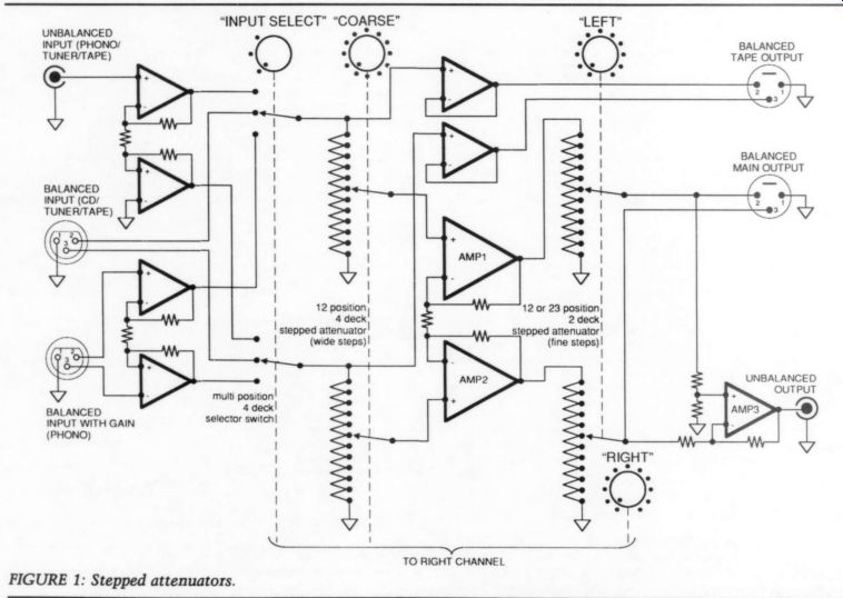
FIGURE 1: Stepped attenuators.
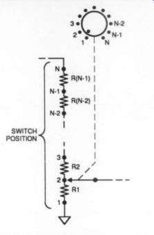
FIGURE 2: Use this diagram and the listing in Table 1 to construct the stepped attenuators in Fig. 1. "N" is the number of switch positions.
Now, I renew my plea for stepped attenuators and present a balanced version for those considering building their own fully balanced preamplifier.
The simplest balanced attenuator is a ganged pair of potentiometers connected so one pot attenuates the negative side of the signal while the other attenuates the positive. (Sounds like a jingle: ‘Attenuate the positive, eliminate the negative. ’) Constructing a balanced attenuator is like constructing a single-ended one, except you have twice as many attenuators. A stereo balanced attenuator requires a four-gang pot instead of the usual two-gang. It is easier to find a four-gang switch (especially in the 12-position size) than a four-gang pot, hence Mr. Borbely's consideration of stepped attenuators for his balanced preamplifiers.
The circuit in Fig. 1 shows a balanced attenuator added to Mr. Borbely's circuit for a fully balanced signal-processing preamp (his Fig. 18). In Fig. 1, I have assumed you will follow the approach presented in my article in TAA 3/89, but if you prefer the standard approach of a single volume control, eliminate the second set of stepped attenuators, refer ring to TAA 4/88 for the instructions and to column 1 of Table 1 for the resistor values.
---------------
ABOUT THE AUTHOR
Joseph O'Connell received his B.A. in history and philosophy of science, graduating from the University of Chicago with highest honors, and plans to work as a professional historian or inventor. He has electronic experience as a hobbyist and is the author of 20 Innovative Electronic Projects for Your Home (TAB Books).
--------------
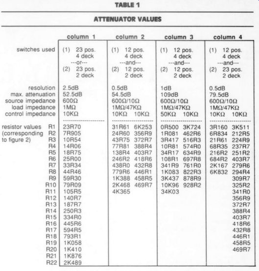
TABLE 1 ATTENUATOR VALUES
The attenuator in column 1 is the standard kind with a single knob (or a separate one for each channel). The others use two separate attenuators as shown in Fig. 1. Columns 2 and 3 use 12-position switches; the difference between them is the resolution and the maximum attenuation. Column 4 is an attenuator that uses a 12-position switch and a 23-position switch to achieve fine resolution and wide range.
-----------
If you are willing to try my preferred approach to volume controls, I have included three sets of resistor values in columns 2, 3, and 4 of the same table, and as always, Old Colony has Macintosh computer programs that will select values for you if you have an unusual number of steps or unusual source and load impedance.
To create the lists of resistor values, I assumed the source impedance to the first set of attenuators would be 600 ohm and the load impedance would be 11 M-OHM.
For the second set of attenuators, I assumed a source impedance of 10 ohm and a load impedance of 47 k-Ohm. The amount of attenuation at each switch position for a balanced attenuator is the same as if each attenuator were single-ended acting in a single-ended circuit. Thus, no modifications of the computer programs were required to obtain the correct resistor values for the step size desired.
Keep in mind, however, that attenuation is always relative to the maximum volume possible from a circuit and that the balanced preamplifier you construct may have more gain than a single-ended preamplifier; therefore, you may need a control capable of greater attenuation.
The resistor values in column 2 permit a total attenuation of 54.5dB (that's the price of steps as fine as 0.5dB). This may not be enough for some circuits, but the values in columns 3 and 4 give 79dB, which should be more than enough.
Although not related to the attenuator, the tape outputs in Fig. 1 deserve a few comments. For clarity, I have followed Mr. Borbely's Fig. 18, taking the tape output from the same switch as that which selects the input to the main amplifier. However, for maxi mum flexibility, a separate 'record select’ switch should be dedicated to the tape output jack, as in Mr. Borbely's Fig. 17.
++++++++++++++++
Also see: