Build the BALANCED-JACK
CLEARLY, A DIFFERENTIAL system is superior to unbalanced audio systems in many respects. It has numerous merits and is especially good for distributed audio and component systems. Implementing differential audio systems, however, can be daunting for some, especially when tackling designs with transformer-like output (TAA 1/91, p. 17, Fig. 11).
Fortunately, PMI, a division of Analog Devices, recently introduced the SSM-2142, a device providing differential transformer-like output. PMI's pair of low-cost devices (the SSM-2142 differential line driver and the SSM-2141 high-CMRR differential receiver) make it a snap to convert any “unbalanced ” audio system to one with differential connections between each piece of equipment.
In this article, I will outline the con version process. The Balanced-Jack (Bal Jack) system is made from two separate assemblies, a “transmitter” and a “receiver.” (Use of the terms transmitter and receiver is not meant to imply this project involves radio transmission, I use them to describe each assembly's function).
The Ins and Outs
The transmitter is designed to accept two unbalanced signals (left and right) as inputs. It then converts each of these signals into a pair of separate differential signals (one each for the right and left channels), and finally it transmits these signals into a cable specifically designed to carry a pair of differential signals. The transmitter typically connects to the “OUT ”' RCA jacks of any piece of audio equipment.
The BalJack System is designed to connect components of an audio system together and to work with line level signals. It is not designed to handle out puts from a power amplifier.
The receiver accepts a pair of differential signals created by the transmitter, re-creates the unbalanced versions of the original left and right signals, and then provides these two separate signals as outputs. Typically, you would connect the receiver to the “IN” RCA jacks of your audio equipment.
Obvious
Options
You can use the BalJack as a building block to customize systems to work ...
---------------------
Ballack Transmitter
by Artronix
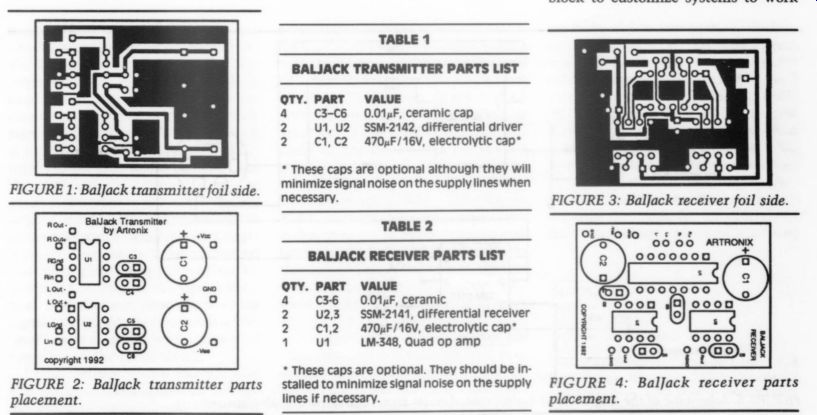
FIGURE 2: Baljack transmitter parts placement.
TABLE 1
QTY. PART VALUE
4 C3-C6 0.01 uF, ceramic cap
2 U1, U2 SSM-2142, differential driver
2 C1, C2 470 uF/16V, electrolytic cap
These caps are optional although they will minimize signal noise on the supply lines when necessary.
TABLE 2 BALJACK RECEIVER PARTS LIST VALUE
0.01 uF, ceramic SSM-2141, differential receiver 470 uF/16V, electrolytic cap
LM-348, Quad op amp
These caps are optional. They should be in stalled to minimize signal noise on the supply lines if necessary.
FIGURE 3: BalJack receiver foil side.
FIGURE 4: Ballack receiver parts placement.
-----------------------------------
... with specific units. With the right mechanical design, a chassis containing the proper amount of BalJack assemblies, you could bolt your system directly to the rear of your audio equipment, and mate it with each of the RCA jacks presently on the rear of the equipment. This method provides a relatively simple way to create a differential interconnection system without having to modify any of your equipment internally.
The less ambitious could build this prototype using the pigtail approach.
This system works well for experimentation, or when differential signaling for each connection is not necessary.
For a distributed sound application, you can use this prototype to transmit line level signal to a remote power amplifier. The BalJack transmitter connects to the signal source via an RCA pigtail. The receiver connects to the transmitter through a shielded four conductor cable, and also to the remote amplifier using an RCA pigtail.
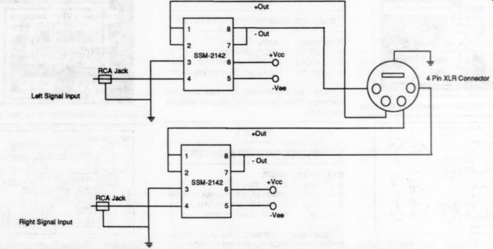
FIGURE 5: Schematic of the single-ended to differential audio signal converter circuit (transmitter).
------------
Hints for a Good Build
If you study the schematic diagrams carefully, you may notice that while the signal ground is connected to the XLR jack in the BalJack transmitter assembly, it is not in the BalJack receiver assembly.
I created this ground-circuit connection scheme purposefully. Also, because more than one signal channel is propagated in a single cable, you should exercise caution when connecting cable conductors and XLR assembly pins.
One reason to transmit signals using a differential signal system is to break any potential ground loop between different pieces of equipment. You may notice the ground circuit connecting the transmitter circuit to the XLR jack is the signal ground in the transmitter circuit.
If a ground connection is also in the receiver assembly, the potential for a ground loop is again introduced. While the additive nature of the differential receiver may compensate for any disturbances in the ground reference circuit, it is better to avoid introducing the possibility by leaving the ground circuit “open ” at one end of the cable. This method effectively prevents ground loop currents.
Tying the cable's ground shield to a ground reference rather than allowing it to “float ” is still desirable. A floating ground is undesirable because it has little capacity to block or absorb spurious environmental events which potentially add to signal distortion. This is the reason the influence of the signal ground is “extended” over the length of the cable by connecting it to a ground at one end or the other. This XLR cabling technique is used quite widely in professionally installed systems.
I chose to use the transmitter as the cable ground reference point in this prototype although the receiver circuit ground would also have sufficed. The choice is arbitrary. The only rule to re member is that only one XLR connector should connect to a signal ground in one or the other assembly.
1. Disassemble the XLR cable plug by removing the two screws from the rear of the connector shell holding the strain relief in place and also loosen the screw holding the molded pin carrier.
(The screw attached to the pin carrier is often reverse threaded and penetrates the connector body with right hand rotation.)
2. Slide the pin carrier out of the XLR connector's shell and remove the rubber strain.
3. Slide the XLR connector's rubber strain relief, its outer shell, and the internal plastic insulating ring over the cable far enough so they do not get in the way.
4. Carefully strip away the outer sheath of the cable. Try not to damage the fine braid of wires that make up the cable's ground shield.
5. Separate the inner conductors from the ground shield. Either comb out the braid or spread open a small hole in the braid by pushing the wires back. This step requires a little patience. (Do not cut the shield away, it is used later in the assembly process.)
6. Find the twisted pair of conductors. Try not to change the number of twists per inch as you work with each cable pair. Solder the twisted pair to the pins of the XLR assembly. Each twisted pair carries one of the audio channels, so the wires of the twisted pair should connect to the pins in the XLR connector carrying a single audio channel. For instance, one of the twisted pairs will connect to the XLR pins carrying the right audio channel so the conductors of this twisted pair connect to right channel positive and the other wire of the pair connects to right channel negative.
7. Repeat Step 6 for the second twisted pair. After soldering the twisted pairs in place, connect the ground braid to the pin carrier assembly's ground lug. Do not make too much of a “pile ” on this connection or you may have trouble getting the outer shell on.
8. Slide the pin carrier into the connector shell and tighten its retaining screw. Slide the strain relief into the rear of the connector shell and tighten its retaining Screws.
9. Prepare the second end in the same manner. Use a continuity test to identify which of the twisted pairs connects to the right channel on the finished end so you will choose the correct pair to connect to the right channel on the second end. Verify this before soldering any connections on the second cable end.
Also make sure that no phase inversion takes place in the cable by checking to see whether the positive and negative signals for each channel connect their corresponding pins.
-----------------------------
Of Cabling and XLR Jacks
An XLR connection carries balanced signals. To perform this function, it offers two conductors for each signal pro pagated through the system. One con ductor carries the input signal's “positive ” representation and the second car ries the “negative ” (180° phase rever sal). The cable pairs may or may not be twisted around one another (depending on the cable and supplier).
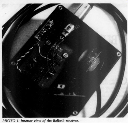
PHOTO 1: Interior view of the Ballack receiver.
Twisting the signal-carrying conduc tors provides two functions: It cancels emissions from the cable because the opposing polarity of the signals creates self-canceling fields. Also, twisting the wire pairs tightly around one another helps isolate the signals from any oth ers present in the cable by removing some of the potential for near-end and far-end crosstalk between different audio channels. Twisting the wires also serves to subject each of the signals to nearly identical interference from the outside environment. Any interference present on the signals will be on each of the wave forms (the positive and the negative) for that audio channel, and therefore will be removed from the signal at the receiver due to the method used to combine the differential signals into a composite signal (positive-negative). Placing the two conductors on 'the same plane’ helps to keep the interference on each of the signals identical. Manufacturers generally place the signal-carrying conductors inside a “coaxial ” cable assembly with exceptional shielding in the cable sheath.
I built BalJack with a four-pin XLR connector and a four-conductor (two audio channel) shielded cable to allow ground and stereo channel transmission through a single cable. Some purists may argue I am asking for trouble; twin three-pin XLR connectors and a two conductor (single channel) shielded audio cable would provide the best signal isolation. This design decision was made to minimize both cost and the chassis' dimensional requirements (one five-pin XLR plug body as opposed to two three-pin plug bodies). Reducing the XLR connectors space requirements also makes it easier to build a chassis containing multiple BalJack building blocks that would bolt to existing equipment with RCA jacks. One XLR occupies approximately the same amount of space as a pair of RCA jacks.
The decision to add more than one audio channel per cable to your own system depends upon what type of cable you use to connect the BalJack transmitter to the receiver. Obviously, it would be highly undesirable if the left and right-channel signals were subject to an extreme amount of crosstalk in the cable. The manufacturer of the cable I used in the prototype, Canare L-4E6S, certifies it has at least 90dB crosstalk damping at 10kHz and better than 110dB at midband frequencies. This level of crosstalk damping is more than adequate for stereo transmissions in professional applications. So, if your project uses this cable (or an equivalent) then you may consider propagating both channels in a single cable as I did with the prototype.
SUPPLIER
Artronix PO Box 221393 Sacramento, CA 95822, (916) 452-9041
SSM-2141, SSM-2142, Canare Cable, XLR 5-pin chassis mount jacks, XLR 5-pin cable and assembly, XLR 3-pin chassis mount jacks, XLR 3-pin cable end assembly
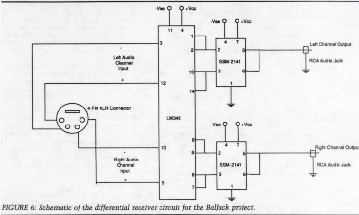
FIGURE 6: Schematic of the differential receiver circuit for the BalJack project.
The Circuit
Primarily designed for high performance audio systems, the BalJack transmitter uses the SSM-2142 balanced line driver from PMI. The SSM-2142, a fully integrated analog-function block in an 8-pin DIP, creates a precision balanced output from any single ended input. The device drives 10V RMS into a 600 ohm load and functions much like a transformer based circuit. Its low gain error (0.1%) and high slew rate (15V/mS) make it ideal for audio applications that require balanced outputs or high drive capability. This device requires no external components and is short-circuit protected. The Balanced-Jack transmitter is a straight forward application of this device.
The receiver makes use of the SSM 2141, also from PMI. This device is an other analog building block in an 8-pin DIP. This differential amplifier is intended to receive balanced audio signal inputs in systems that require high level noise immunity and exceptional CMRR. This device sports a CMRR of 100dB at DC and 70dB at 20kHz. According to PMI, the best CMRR in a differential amplifier fabricated with op amps and precision resistors is 40dB--not adequate for high performance audio systems. The SSM-2141 maintains its low distortion specifications (0.002% across the audio spectrum) by having a high slew rate (9.5V/mS) and a high open-loop gain.
Both of these circuits benefit from proper power-supply bypassing, so you should take every measure to make the power supply as stable and as noise free as possible. The SSM-2141 is particularly sensitive to unbalanced source resistance and/or source reactive impedance. Unbalanced source resistances will result in degrading the CMR of the device. In fact, an imbalance of 5 ohm can degrade CMR by as much as 20dB. In order to maintain CMR across the audio band, you must carefully match the source reactive impedance. The unity gain op amp circuits on each input to the 2141 isolate this device's inputs from the multiple connections between it and the 2142's outputs.
Together, these two devices comprise the heart of a high-performance differential signal-transmission system functionally equivalent to transformer coupling, but with less distortion, EMI fields, and cost.
Many Thanks
The folks at PMI have done audio amateurs a great service. These two devices make creating balanced transmission systems much easier to accomplish.
Relatively low in cost, they provide incentive to experiment with balanced transmission systems. Whether you experience problems with induced noise (have you ever lived next to a transmitter tower?), are curious about the dynamics of differential systems, or simply tired of going into debt to buy gold plated connectors and monstrous cables, I recommend a BalJack system.
------------------
NOTE: Signal Ground is connected at one end only.
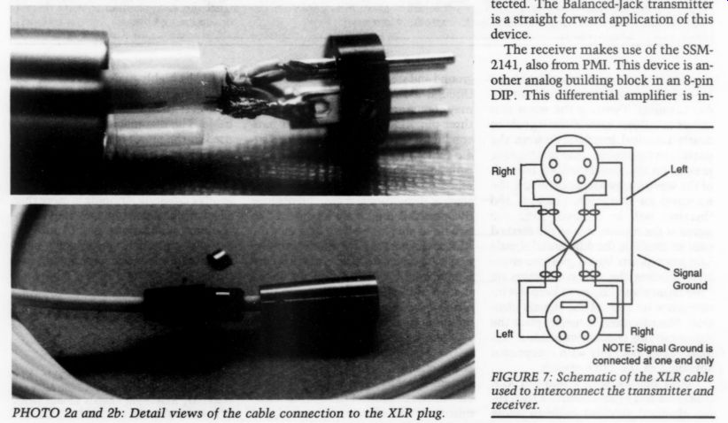
FIGURE 7: Schematic of the XLR cable used to interconnect the transmitter and receiver.
PHOTO 2a and 2b: Detail views of the cable connection to the XLR plug.
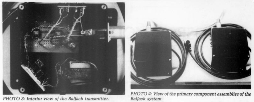
PHOTO 3: Interior view of the Baljack transmitter.
PHOTO 4: View of the primary component assemblies of the BalJack system.
-------------------
BY MICHAEL SWARTZENDRUBER
------------------------
Also see:
POOGE-5: RITE OF PASSAGE FOR THE DAC960, A TWO-PART SAGA, part 1