HIGH-QUALITY AM FROM A CRYSTAL RADIO
THIS ARTICLE DESCRIBES the construction of a quality AM mono receiver based on the design of the crystal radio.
Photos 1 and 2 show two versions of the receiver. Like the traditional crystal radio, this receiver can be used with headphones, but it is intended to be connected to an audio system containing a power amplifier, speakers, and an audio recorder. An indoor long-wire antenna about 25' long is needed at the receiver site.
A ground for the receiver usually improves performance, but may not be required when it is used with an audio system. The audio system connection will provide some radio-frequency (RF) ground. Alternatives to a long-wire antenna and ground are a remote active antenna with a coaxial feed to, or an active loop or rod antenna at, the receiver site.
AM Radio
In the 1970s FM radio began to overtake the traditional AM band in popularity. FM radio is characterized by low-noise, low-distortion, high-frequency audio response and stereo availability. FM achieves this quality by occupying a frequency band space of about ten times the size of a double-sideband AM signal. Today the preference for FM is almost universal. But there are still 4,900 AM stations in the United States (compared to 5,900 FM stations), and many of these have a musical format, which in many localities is available only on AM.
Nearly all AM receivers deliver a muddy sound resulting from nonlinear intermediate-frequency (IF) amplifiers, too narrow an IF bandwidth, and de modulating with a single-diode detector. Nevertheless, radio quality can be very good when via a good receiver.
Vintage tube-type communications receivers often are used for quality reception of distant AM stations. Many of these have crystal or mechanical filters designed for a wide IF response with steep skirts. Nearly all modern receivers are too narrow in bandwidth for quality music reproduction. A few AM tuners have a good sound, but are very expensive.
The technique described here produces about as much audio quality as possible from a local AM signal. I ex plain how to modify a crystal radio by substituting an envelope detector for the original single diode. The cost of this approach is only a fraction of the cost of a quality AM superhet. From here on, I'll refer to the combination of a crystal radio resonant circuit and envelope detector as the envelope receiver.
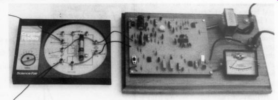
PHOTO 1: A commercial crystal set coupled to the envelope detector (the toy look).
The wire at the upper left is the antenna, the wire at the lower left is the ground, the wire at the upper right is the 117V AC cord, and the cable at right center is the audio output cable to an audio system.
Crystal Radio
The term 'crystal radio‘ refers to the single-tuned-circuit, unamplified radios used with headphones that were popular in the 1920s. The word ‘crystal ‘ refers to the mineral used as a passive detector (similar to the modern diode) and should not be confused with the quartz crystal used in frequency-deter mining circuits. In the '50s, amateur experimenters discovered that when the output of a simple crystal radio was connected to the input of a quality audio amplifier, the sound was better than that available from most superhet radios and tuners. When the crystal radio is receiving strong local stations, its wide bandwidth and absence of distorting amplifiers are audio advantages.
For economic reasons, AM stations today use a greater percentage of modulation than was generally used in the 1950s. This results in greater distortion when detected by a single-diode detector. This is true whether the diode is in a crystal radio or a superhet.
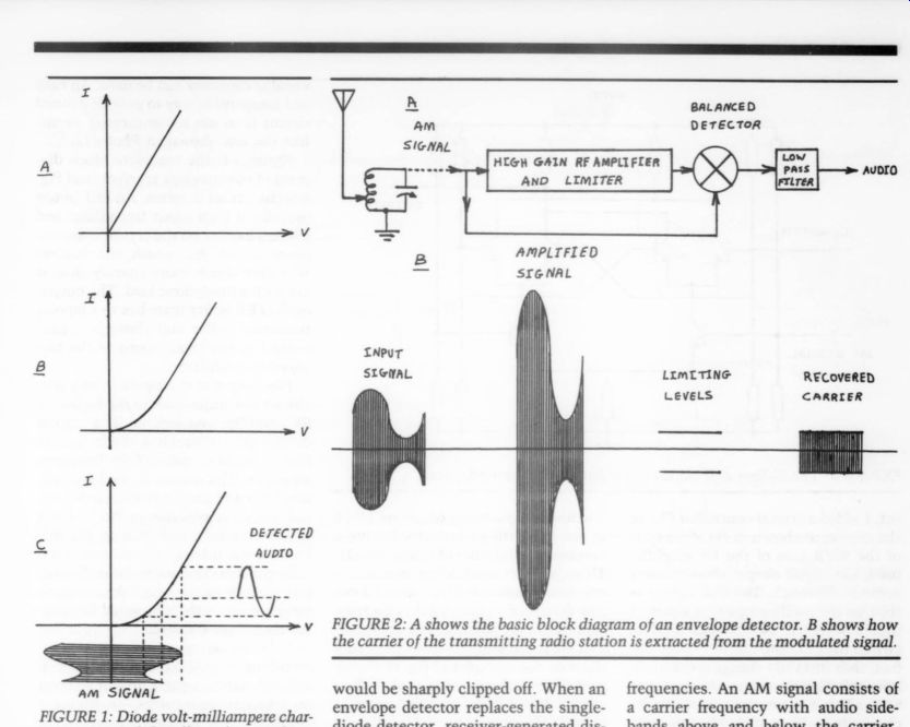
FIGURE 1: Diode volt-milliampere characteristics and the effect of curve shape on demodulation. A is an ideal diode curve, which can never be obtained in a real device. B is an exponential curve that is characteristic of real diodes. C shows how the nonlinear diode curve distorts the envelope of the AM signal.
FIGURE 2: A shows the basic block diagram of an envelope detector. B shows how the carrier of the transmitting radio station is extracted from the modulated signal.
An ideal diode has a volt-milliampere characteristic, as shown in Fig. 1a. It be haves as a resistor in the forward direction and as an insulator in the reversedirection. Real diodes have a reverse characteristic that is close to ideal, but they have an exponential characteristic in the forward direction, as shown in Fig. 1b. This forward direction curvature is greater in junction diodes and less severe in point-contact and vacuum tube diodes.
Figure 1c shows how, in the demodulation process, the diode produces distortion due to suppression of the amplitude of the negative half of the audio waveform. This negative-half-cycle suppression usually can be seen on an oscilloscope connected to the audio output of any receiver that uses a single diode detector. The modulation index shown in Fig. 1c is only 35%. If the modulation index were increased closer to 100%, the negative half of the audio would be sharply clipped off. When an envelope detector replaces the single diode detector, receiver-generated distortion is greatly reduced.
The Envelope Detector
A generalized block diagram of an envelope detector is shown in Fig. 2a. The AM signal is fed into a very high gain RF amplifier and limiter. The output is a square wave that is equivalent to the radio station carrier in both frequency and phase. Figure 2b shows how the carrier signal is extracted from the modulated signal. A gain of 2.6 is shown in Fig. 2b. The actual gain produced by IC4 is over 30,000. The carrier signal goes to one input of an AM demodulator circuit, which is essentially an analog multiplier. The demodulator circuit often used in ICs is called a Gilbert cell. The approximate circuit diagram is shown in Fig. 3.
The AM signal in Fig. 2a is applied to the other input of the demodulator circuit. In effect, the AM signal is electrically multiplied by its own carrier.
When two frequencies are multiplied, there is one output that is the sum of the two frequencies and another output that is the difference between the two frequencies. An AM signal consists of a carrier frequency with audio side bands above and below the carrier.
When this signal is multiplied by its own carrier frequency, one output is a carrier of zero frequency (DC) accompanied by the audio sidebands, which are the detected audio. The other output is a signal of twice the carrier frequency plus the audio sidebands. This signal is removed by a low-pass filter.
The balanced configuration of the de modulator circuit helps eliminate carrier feedthrough to the output.
In the envelope detector shown in Fig. 2a, some audio can be seen at the limiter output. If a narrow-band phase locked loop (PLL) is placed between the limiter and the balanced detector, as shown in Fig. 4, the audio will be completely removed from the carrier signal.
In fact, the PLL will continue to sup ply a carrier signal to the demodulator even if the input carrier is missing for a few cycles. The condition of missing carrier cycles would occur if the modulation index exceeded 100% momentarily. When the PLL is added to the envelope detector, the resulting circuit is known as a synchronous detector.
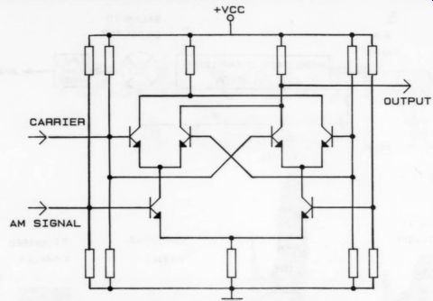
FIGURE 3: The Gilbert cell circuit often found in IC demodulators.
During the development of this project, I added a crystal-controlled PLL to the circuit, as shown in Fig. 4. In spite of the 90dB gain of the RF amplifier used, the carrier output showed some audio feedthrough. The PLL output as seen on the oscilloscope was a perfect square wave. A switch was used to switch the PLL into and out of the circuit, thus instantly changing the mode from envelope to synchronous and vice versa. This is a very powerful test for change in audio quality. No difference in audio quality between the two modes of operation was noticeable. With input signals of 100mV (and probably much less), this envelope detector performs as well as the much more complicated and difficult-to-tune synchronous detector.
An alternative use of the envelope detector is as a replacement for the di ode in a wide-bandwidth superhet. The envelope detector can be connected across the secondary of the last IF trans former. That transformer may require realignment because of the envelope detector's small input capacitance. Leave the diode connected to the IF trans former so that the automatic gain control (AGC) system in the superhet will still work. Used with a high-quality superhet, the envelope detector will provide an output with less distortion.
With the average narrow-band super het, you would probably not notice any improvement.
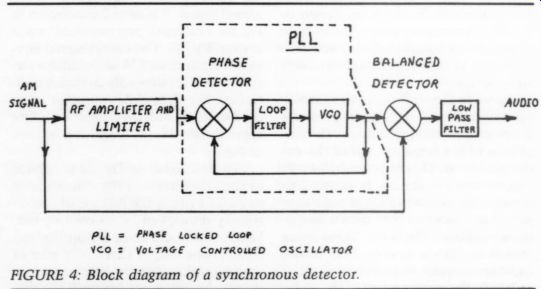
FIGURE 4: Block diagram of a synchronous detector.
Circuit Description
[...]
The tuned circuit of a crystal radio is usually a parallel resonant circuit consisting of a variable capacitor with a maximum capacitance of around 240pF in parallel with an inductor having a maximum inductance of around 340uH.
This circuit is coupled to an antenna and ground system. More than 30 circuit designs for the crystal radio resonant circuit are possible. The configuration with the antenna connected to a slider on the coil (part of Fig. 6) is very good. This configuration is needed when a coaxial feed from an active antenna is used. The tap on the coil is adjusted to provide a 50 ohm match for the coax.
Coils can be wound on wood, card board cereal boxes, or disc-like ‘‘spider” forms, or they can be stagger-wound in the self-supporting ‘‘basket ” style. You can purchase a new fixed or adjustable ferrite antenna coil or remove one from a discarded radio. A traditional air variable or modern plastic dielectric-variable capacitor can be used. An easy and inexpensive way to provide a tuned circuit is to use a commercial circuit like the one shown in Photo 1.
Figure 5 is the complete block dia gram of the envelope receiver, and Fig. 6 is the circuit diagram. An FET buffer provides a high input impedance and reduces loading on the crystal radio resonant circuit. As a result, the receiver will tune much more sharply than it did with a headphone load. The output of the FET buffer branches to a bipolar transistor buffer and through a gain control to the signal input of the balanced demodulator.
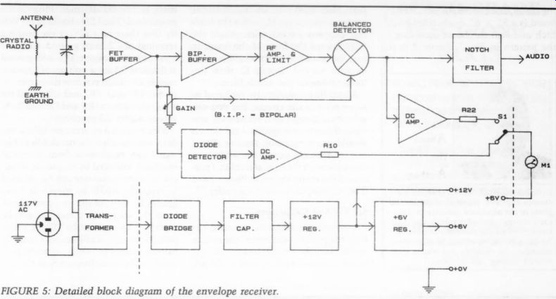
FIGURE 5: Detailed block diagram of the envelope receiver.
The output of the bipolar buffer pro vides a low impedance to the high-gain RF amplifier and limiter. The bipolar output goes through a diode limiter that prevents overload of the high-gain amplifier. The output of the high-gain amplifier and limiter is the carrier signal, which is available at Pin 9 of IC4 and is coupled inside IC4 to the balanced demodulator. The output of the balanced demodulator is the audio output. Capacitors across the demodulator output remove the unwanted RF components from the audio.
AM stations are spaced at 10kHz intervals on the AM band. A local station will heterodyne against distant stations on adjacent frequencies, producing a 10kHz screech. Because this receiver is wideband, the screech will be quite audible. A Wien bridge notch filter that re moves just the 10kHz intercarrier tone and passes all other frequencies is connected to the output of the balanced de modulator. The output of this notch filter is fed to the output jack. This output impedance is 1k-ohm and is suitable for driving the input of an external audio system or headphones. If you are going to use headphones, replace C27 with a 3.3uF or larger axial electrolytic capacitor, with the positive lead going to R31.
Two tuning meter circuits are pro vided with a selector switch. One is derived from a diode detector and is in dependent of the RF gain control set ting. This circuit gives a reading of absolute signal strength and is useful in selecting different antenna and ground options and in noting the relative signal strength of different stations. The other tuning meter circuit is connected to the output of the balanced demodulator and is useful for setting the RF gain control at a level that won't overload the demodulator. Either setting of the switch can be used to tune the radio precisely to a given station. As the crystal radio resonant circuit now tunes sharply, this feature is more useful than might be expected.
The power supply circuit provides regulated voltages of + 12V and + 6V.
For the op amp circuits, the + 6V sup ply is used as ground, the 0V line is --6V, and the +12V line is + 6V.
Construction
Photos 1 and 2 show two possible physical layouts for the envelope receiver.
Photo 1 might be called the toy image, and Photo 2 the antique image. You may prefer to build the project in a metal or plastic enclosure, resulting in a contemporary image. If so, the variable tuning capacitor, R14, S1, the LED, and the tuning meter would all be mounted on the front panel of the enclosure. A ferrite antenna coil could be mounted inside the enclosure as far away from the metal surfaces as practicable.
Because IC4 is a very high gain (90dB) amplifier that is prone to instability, I recommend that you build the circuit on a PC board and that no IC socket be used for IC4. I built a successful prototype on perfboard, but I used heavy ground bus wire around IC4.
All parts are contained on the PC board except the crystal set resonant circuit, the power transformer, the tuning meter, and the output jack. The PC board is a 5 ” x 6 ” single-sided board.
Etch and drill the board according to the pattern in Fig. 7. Figure 8 is the
------------------
About the Author
Lyle Russell Williams is a graduate electronics engineer. He worked for several years in the aerospace industry in space craft testing, applied research, and electronics design. He currently has his own business providing noncredit electronics education for children and adults, electronics writing, and lecturing.
-----------------
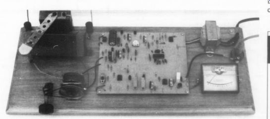
PHOTO 2: A traditional wooden coil crystal set mounted on the same board with the envelope detector (the antique look). The wire toward the top of the photo on the left is the ground, and the wire toward the top of the photo on the right is the antenna. The heavy wire at the upper right is the 117V AC power cord. The cable at right center is the audio cable to an audio system. The dial cord and pulley mechanism provides a turning ratio of 8:1, which is about right for this receiver.
-----------------
... parts placement diagram. Insert all the components except J2; solder the leads and clip any excess wire. Angle the LED toward the front of the board to face the direction from which it is ordinarily viewed. Install J2 after you have calibrated the notch filter.
Metal film resistors are preferred in some parts of the circuit, but you can substitute carbon film resistors if you wish. If a resistor is specified as 1%, you should use a precision resistor. Panel meters are very expensive when purchased new on the regular market. I purchased the meter shown in Photos 1 and 2 on the surplus market for under $4.
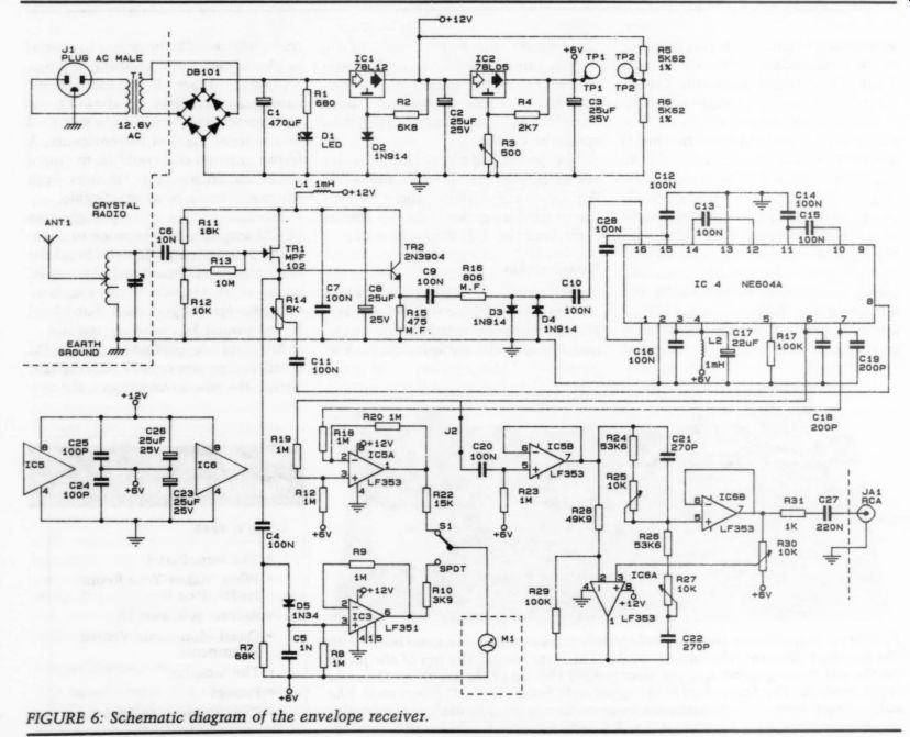
FIGURE 6: Schematic diagram of the envelope receiver.
Set Up And Calibration
Connect the crystal radio resonant circuit, the power transformer, the tuning meter, and the output jack to the PC board. Connect a power cord to the primary of the transformer. Plug in the power cord. The LED should light. Verify that there is + 12V at the positive terminal of C2 from ground. Connect a voltmeter between TP1 and ground and adjust R3 for a voltage of approximately 6V. Then connect the meter be tween TP1 and TP2 and adjust R3 for a voltage of zero. R5 and R6 will help you to adjust R3 precisely.
You will need an accurate 10kHz audio source to align the notch filter. The signal can be derived from a crystal oscillator followed by frequency dividers, an audio generator can be adjusted to precisely 10kHz by means of a frequency counter, or the intercarrier tone from the output of a receiver can be separated by means of a 10kHz band pass filter. An oscilloscope Lissajous pattern is used to adjust an audio generator to the same frequency as the signal from the bandpass filter. Although this third method is cumbersome, it has been used with success.
Connect the 10kHz source with about 1V output between TP3 and ground. J1 is a convenient ground point.
Apply power to the envelope receiver.
Connect the output of the board to headphones or an audio amplifier capable of a 10kHz response. Also connect an oscilloscope to the output of the board. Adjust R30 for maximum gain (the slider nearest to Pin 7 of IC6, farthest from ground). Use both the sound and the oscilloscope pattern to adjust the 15-turn trimpots R25 and R27 for a minimum output. The notch filter is now calibrated. Install J2 on the board and solder it in place.
The intercarrier tone is usually audible at night, when faraway stations on channels adjacent to that of a local station are received stronger than during the daytime. Connect a crystal radio resonant circuit with antenna and ground to the circuit board. Apply power
----------------------
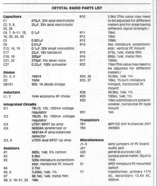
CRYSTAL RADIO
PARTS LIST
Capacitors C1 470uF, 25V axial electrolytic Co 25uF, 25V axial electrolytic 23, 26 ca, 7, 9-11, 13, 16, 20, 24, 25 C5 0.0014F C6 0.014F C12, 14, 15 0.1xF, 50V small monolithic c17 22uF, 16V tantalum C18, 19 200pF 2 270pF, 5% silver mica C27 0.22uF, 100V polyester
0.1u4F Diodes D1,3, 4 1N914 D2 1N34 DB101 50V, 1A diode bridge inductors 1,2 1mH economy RF choke Integrated Circuits IC1 78L12, 12V, 100mA voltage regulator IC2 78L05, 5V, 100mA voltage regulator IC3 LF351 BIFET op amp Ica NEG604A (preferred) or NE614A IF amp-balanced detector IC5, 6 LF353 dual BIFET op-amp
Resistors R1 680 ohm, 2W, 5% carbon R2 6.8k-ohm R3 5000 miniature potentiometer, horizontal PC mount R4 2.7k-ohm R5, 6 5.62k-ohm, 0.25W, 1% R7 68.1k-ohm, 0.25W, metal film R5, 9, 18-21,23 1M-OHM
R10 3.9k-ohm (This value may need to be adjusted for different meters and for areas having different signal strength.) 18k-ohm 10k 10M-OHM 5k2 miniature potentiometer, vertical PC mount 4750, 0.25W, metal film 806 ohm, 0.25W, metal film 100k-ohm 15k-ohm (This value may need to be adjusted for different meters.) 53.6k-ohm, 0.25w, 1% 10k, 15-turn miniature trimpot, horizontal PC mount R28 49.9k-ohm, 0.25w, 1% R29 100k, 0.25w, 1% R30 10k-ohm subminiature potentiometer, horizontal PC type mount R31 1k-ohm
Transistors
TR1 MPF102 VHF N-channel JFET
TR2 2N3904 Miscellaneous J1-3 wire jumpers of PC board
JA1 audio jack LED general-purpose LED
M1 surplus panel meter, 50, At 0 1mMA
$1 SPDT miniature PC-mounted switch transformer, primary 117V AC, secondary 12.6V AC, 300mA
PC board, 5 ” x 6 ” single sided, etched according to the foil pattern of Fig. 7.
Tuner section of a crystal radio: home-built traditional version or commercial version such as the Radio Shack #28-177 shown in Photo 1.
Wooden board or cabinet enclosure for mounting components.
All resistors are 0.25W, 5% carbon unless otherwise specified.
All capacitors are 50V, 10% general-purpose ceramic unless otherwise specified.
Assuming that a $4 surplus meter is used, that the PC board can be reproduced for $6, that the Radio Shack #28-177 crystal set ($7) is used, and that all other parts are purchased new at single quantity prices, a complete receiver can be constructed for $52.
All parts are commonly available except IC4 (NE6G04A /NE6I4A). This part can be obtained for $9.75 postpaid from DC Electronics, PO Box 3203, Scottsdale, AZ 85271-3203. Write for quantity prices.
The part also can be obtained from BCD Electro, PO Box 450207, Garland, TX 75045-0207.
-------------------------
-------
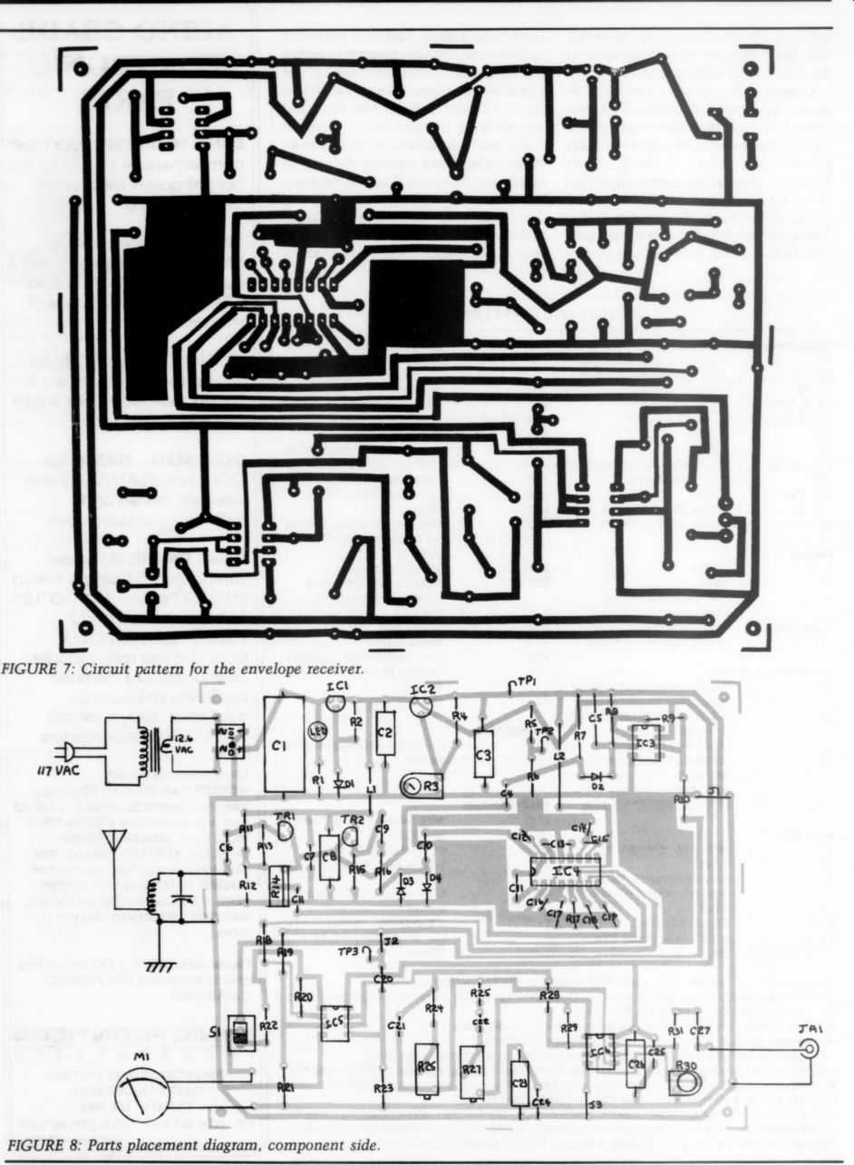
Fig. 7, 8
.... and tune in a local station. Verify the removal of the intercarrier screech by comparing the audio from Pin 7 of IC5 (with a 0.22uF capacitor in series) with that from the board's output terminal.
The audio may be improved by backing off R30 somewhat from its maximum position. This widens the notch and removes some harmonics close to the intercarrier tone.
Resistors R10 and R22 control the sensitivity of the tuning meter in the two positions of S1. These resistors will have to be selected to match the sensitivity of the meter chosen (if it's not 300uV).
Switch S1 to the diode detector position. R10 should be chosen to produce a nearly full-scale reading with the strongest local station. Switch S1 to the opposite position. To select R22, tune in a strong station and turn up control R14 until distortion is just audible in the output. Select R22 so that the tuning meter reads about full scale. Hereafter, when you tune in a new station, adjust gain control R14 until the meter reads about one-fifth of full scale.
Troubleshooting
If you have trouble, check the 6V and 12V power supply voltages (positive terminals of C3 and C2) with a voltmeter.
Also check the supply voltages with an oscilloscope to verify the absence of ripple. With the input shorted, the voltages at the output of all op amps should be nearly zero with respect to the + 6V supply. Check Pin 6 of IC3, Pins 1 and 7 of IC5, and Pins 1 and 7 of IC6. If they're not zero, check the supply voltage, bias components, and IC.
You can use signal tracing techniques. Connect an AM signal of about 100mV to the input. Using an oscilloscope, you should see the modulated signal at the emitters of TR1 and TR2 and at Pin 8 of IC4 (unless R14 is all the way off). You should see a partially limited signal at Pin 16 of IC4 and a highly limited signal at Pin 9 of IC4. Detected audio should be visible at Pins 6 and 7 of IC4, Pin 6 of IC3, Pins 1 and 7 of IC 5, and Pin 7 of IC6. At the location where the signal is lost, check the supply volt ages, passive components, and transistors or ICs.
Now you're ready to use your new receiver. Just sit back and enjoy those AM stations that you've been missing for so long.
-------
Also see: