- Intro
- EDITORIAL--Share Your Wealth
- ASK TAA
- JUST LOOKING
- LETTERS
-------
Count on TAA to provide essential information on the latest audio developments, as in this issue's lead article, a 'must read' by Norman Thagard and Nelson Pass, 'Build the A75 Power Amplifier'. The well respected Pass A40, which first appeared in TAA 4/78, has been modified and updated, and the story behind its metamorphosis is recounted in this first of a two-part article. Written for the novice as well as the experienced builder, it will prepare you to step into the inner sanctum of amplifier design in preparation for construction, as detailed in our next issue.
You may imagine your turntable to be complete in and of itself, but probably struggle with shock problems. In 'An Anti-Shock Turntable Cradle' , Scott Ellis defines the causes behind turn table angst: impulsive shock and feedback isolation, door slams and foot falls. Once you have learned how to deal with this shocking situation by constructing your own turntable cradle, you can apply it to other devices and be that much closer to perfectly reproduced sound.
AM radio has seldom been a serious consideration for audiophiles, because of interference and narrow bandwidth. Although most of us prefer listening to FM stations, Lyle R. Williams explains how you can turn that around with ‘‘High Quality AM From a Crystal Radio ”. Just when you thought AM and especially crystal radios were passé, a new application could turn them once again into a valuable part of your total listening pleasure.
Whether you've built your own system or just tinkered with parts, no doubt you own a tool you cherish. One you would hate to part with. In Ask TAA, below, GG takes you on a nostalgic trip through time as he describes three decades with his ‘‘Channel-lock” pliers.
Add to your own list of 'essentials' the new products you'll find beginning below in Just Looking.
Just Looking
The latest development from Solo Electronics is an integrated tube amplifier, the Model 323, which features a selectable output power control with two output stage connections: a 50W/channel pentode push/pull, and a 10W/channel triode push/pull. Also featured is a dual independent output binding post, which is wound separately from the output transformer resulting in a bi-wire to bi amplifier connection.
Cost of the 323 is $1,980. For more in formation, contact Solo Electronics Co., 1755 E. Bayshore Rd., Suite 19A, Red wood City, CA 94063, (415) 369-7387, FAX (415) 369-3680.
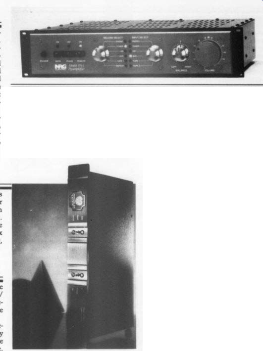
NRG Control introduces its PA-1 preamplifier, with newly designed volume control and balance circuit. The DC control signals are digitized, and control a 6-bit attenuator consisting of 0.1% metal film resistors in a ladder network switched by mercury-wetted relays with negligible and constant contact resistance. The left and right channels track each other within +-0.1dB. In addition, the channel separation is -105dB at 20kHz due to the large physical distance between the left and right attenuators.
For literature and prices, contact NRG Control, Inc., PO Box 389, Walled Lake, MI 48380, (313) 624-0140, FAX (313) 624-6670.
Monarchy Audio has introduced its Model 22A Gold D/A converter, winner of the Best Buy of the Year award from Hi-Fi Review magazine in Hong Kong.
Complete reviews and incentives are available from Monarchy Audio, PO Box 5517, South San Francisco, CA 94080, (415) 873-3055, FAX (415) 588-0335.
KAB Electro-Acoustics announces the Souvenir Vintage Recording Preamp/ Equalizer/Noise Limiter, which will re store the original sound of all vintage records circa 1900-1955.
Corrective EQ is provided by eight response curves, which are selected by electronic switching. A selection table matches labels with the proper curve.
Noise reduction is provided by a true bandstop Scratch Noise Limiter, which passes everything up to 8.5kHz and attenuates anything beyond. A dynamic noise reduction circuit is optimized for vintage records. Reduced bandwidth (15kHz) and two-speed recovery reduce hiss and surface noise. Groove-select switches permit monitoring each groove wall and mono, while switch-through preserves the turntable's stereo operation. Active dual mono outputs eliminate Y cords. The walnut cabinet has vintage styling and a backlit front panel.
Price of the unit is $295 ($5 S/H). A demo tape with instruction manual is available for $3 ($2 S/H). Contact: KAB Electro-Acoustics, PO Box 2922, Plain field, NJ 07062-0922, (908) 754-1479.
The Two-Digit Voltmeter Kit from Decade Engineering is a digital panel meter which is adaptable to different measurement and display applications. Its basic input range of 0.0-9.9V DC may be scaled to meet individual needs. Decimal point LEDs are user-controlled in dependently of the numeric displays.
The kit comes with glass-epoxy PC boards, all electronic components, and assembly instructions. Illustrated pages explain operational theory, with a fully annotated schematic. Solder and input connectors are not supplied.
Contact Decade Engineering, 2302 5th St. NE, Salem, OR 97303, (503) 363 5143, FAX (503) 399-9747.
Accord Electronic Systems' 1992 catalog features over 500 items including resistors, transistors, diodes, bridge rectifiers, capacitors, and more. Accord stocks a wide variety of electronics components and combines the advantages of inexpensive parts with low-purchase requirements.
The catalog is free, and can be obtained by calling (800) 998-2242, or writing Accord Electronic Systems, Inc., 1001 NW 62nd St., Suite 306-D, Ft. Lauderdale, FL 33309, (305) 772-2242, FAX (305) 772-2568.
Snell Acoustics and Audio Alchemy have formed an alliance in order to create a new company called MusicSoft.
The new group plans to develop an open architecture digital signal processing audio computer and a music operating sys tem called MOS.
According to the participants, these products will make it possible to control and manipulate sound in new ways with conventional audio signal processors.
Plans for the new system include the ability to digitally nullify unwanted loud speaker characteristics and eliminate the unwanted acoustic characteristics of the listening room.
The audio computers will be sold un der the Snell Digital brand name and manufactured in the US by Audio Alchemy.
Snell Digital is located at 143 Essex St., Haverhill, MA 01832, (508) 373-6114, FAX (508) 373-6172.
Analog Devices' low-cost SSM-2404 quad audio switch offers four SPST bi lateral switches in a single 20-pin plastic or SOIC package with a maximum ON resistance of 450 (28Q typical). Additional features include total harmonic distortion from 2V RMS (root mean square), 1kHz signals under a 10k-ohm load is 0.0065%, and OFF isolation and cross talk (under identical conditions) of -100dB and - 94dB, respectively. Wide EE i PC Boards' PCRoute ($99), the auto router for PC Boards Layout, now at version 4.0, uses two routing algorithms for up to 95% completion ratios. It has new graphics support, including Super VGA.
PCRoute also has an improved, al most seamless interface with its companion program SuperCAD Schematic.
PCRoute 4.0 still includes the Applicon bravo to PCRoute netlist translation, so it can be used with other schematic cap ture programs. Also included in this new version is via optimization. The program has a completely new look with all-new screens, including a pop-up window user interface, making PCRoute 4.0 easier to use.
Call for an upgrade or further information. PCBoards, 2110 14th Ave. South, Birmingham, AL 35205, (800) 473-PCBS, FAX (205) 933-2954.
band noise density over the full audio bandwidth is 0.6uV P/P.
By adding a single logic inverter, you can connect the SSM-2404 as a DPDT switch for routing stereo signals to or from two sources or destinations. All four switches will open before any one switch reaches the ON state, critical in mixing consoles and other multichannel applications.
Contact Analog Devices, 1 Technology Way, PO Box 9106, Norwood, MA, 02062-9106, (617) 329-4700, FAX (617) 329-1241.
A hex base has been added to Mouser Electronics' panel mount RCA phono jack, allowing a 9 mm nut driver to secure the jack from the front of the panel, and preventing it from turning while it is being tightened from the back. The nut driver minimizes damage to delicate panel finishes. The new phono jack mounts in a single 1/4 “ hole.
Contact Mouser Electronics, 2401 Hwy. 287 N., Mansfield, TX 76063, (800) 346-6873.
Well-known technical and marketing executive C. Victor Campos joined NAD Electronics Ltd. recently as director of product development. In addition to this role, he will be responsible for manufacturing and quality control operations for the entire NAD product line.
Campos held the same title at Adcom for six years. Prior to his stint at Adcom, his private consulting business served such clients as Boston's WGBH, New York City's WNYC, and the CBS Technology Center. He was also in charge of the Audio Division of the consumer Electronics Group of the Electronic Industries Association, as well as a variety of marketing and technical management positions at Acoustic Research and KLH Research and Development Corp.
NetWell Noise Control announces the release of its new AZ-FireFlex Acoustical Foam noise control panels. The light weight noise neutralizer is made of a porous melamine foam, which stands up to spark-hazard applications and meets Class A fire code ratings for flame spread and smoke density (heat resistant to 482 °F).
Panel sizes are 24” x 48” x 2” with custom sizes available, and can be used as either wall panels or as hanging baffles.
NetWell Noise Control is located at 6125 Blue Circle Dr., Minneapolis, MN 55343, (800) 638-9355.
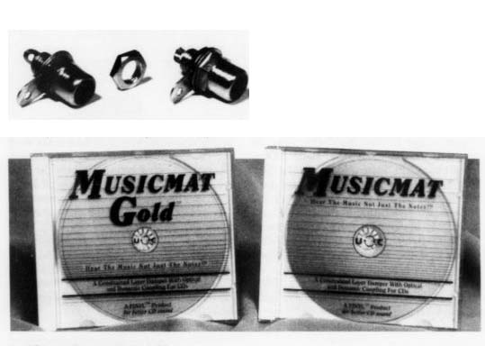
Digital Systems and Solutions has released details on its latest line of dampers, Musicmat and Musicmat Gold , designed to improve the quality of com pact discs. Both devices utilize con strained layer damping, a technology which bonds to the CD through optical and dynamic coupling. It works in most transports, including Laserdisc players.
Musicmat uses a translucent green bottom layer to further improve CD play back by absorbing stray infrared laser light. This layer of material bonds to the CD, keeping it centered and coupled, and absorbing infrared throughout its entire thickness.
Musicmat sells for $49.95 ($3.05 S/H); Musicmat Gold sells for $79.95 ($3.05 S/H). To order, contact Digital Systems and Solutions, 9220 Lavell St., La Mesa, CA 91941-5638, (800) 748-5792.
Stereophile will once again stage its 'Hi-Fi '93-The Stereophile High-End Show,' scheduled for March 12-14, 1993 at the San Francisco Marriott Hotel. This is your opportunity to see and hear more than $2 million worth of high-end brands being demonstrated by dozens of manufacturers and dealers, and to talk to the designers of your favorite audio equipment. Audio enthusiasts from 41 states, five Canadian provinces, and numerous foreign countries have attended previous shows, making this an international event.
Admission to the seminars and live music concerts is included in the admission price. The show is open to the public on Friday, March 12 from 11 a.m. to 8 p.m.; on Saturday, March 13 from 10 a.m. to 7 p.m.; and on Sunday, March 14 from 10 a.m. to 6 p.m. Contact Ralph Johnson, Show Coordinator, at (505) 982-2366 for ticket information.
NAD has introduced a new remote controlled AM/FM stereo receiver, the Model 705, featuring high-dynamic head room, a 40W/channel amplifier, newly developed tuner circuitry, and full system wireless infrared remote control.
The 705 amplifier's continuous power rating is exceeded by 3.5dB dynamic headroom with 8 ohm loads for 85W short term, and delivers 30A peak current.
Seven source inputs include gold-plated jacks to the 705's phonograph preamp section, and two tape-monitor loops with fully independent tape-dubbing facilities enable copying sources to one an other while listening to a third. A new MOSFET tuner design includes a PIN diode automatic gain control supplementing conventional AGC at high antenna-signal levels. The 705 also includes a refined AM tuner with a dedicated adjacent-channel AM notch filter to deliver good AM bandwidth with enhanced noise rejection. Other features include a backlit LCD, which provides frequency display and other indicators. The receiver's volume control is low-impedance and input buffered, and is designed to reduce noise. Full receiver functions include volume, manual and automatic tuning, source selection, independent A/B speaker se lection, and a 10-key-set for direct station and preset access, plus a controller which furnishes unified functionality for full tape-deck and CD player/changer control. The 705 receiver also provides NAD-link input/output jacks so that it may serve as a multiroom controller. For complete information, contact Lenbrook Industries Ltd., 633 Granite Ct., Pickering, ONT L1W 3K1, Canada, (416) 831-6333.
--
Nakamichi has introduced a new cassette deck, the DR-1, a three-head deck which employs the Discrete Head System and the DC-servo-motor-driven Asymmetrical Closed-Loop Dual Capstan Diffused-Resonance transport.
The playback amplifier is integrated with the play head, and is located at the transport mechanism to minimize signal transmission loss. The DR-1 provides an adjustable playback azimuth fine-tune control that enables adjustment for different tapes to ensure full frequency-range performance. Record/ play amplitude response is stated as 20-21kHz +-3dB.
The unit is priced at $879. For more information and specifications, contact Fred Yando at Nakamichi America Corp., 19701 S. Vermont Ave., Torrance, CA 90502, (310) 538-8150.
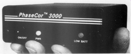
Sound Image has introduced Phase Cor 3000, an analog device which corrects phase distortion by re-establishing the proper phase relationship among complex audio signals. Copy-to-copy ‘‘generation losses” are reduced, thereby increasing the sound quality of the final mix. Eliminating phase distortion also reduces time code pulse distortion. Phase Cor units designed for cassette recorders are also available.
The units ($130) combine studio quality circuitry and components with small size, battery operation, and light weight.
For more information, contact Dave Asche, Sound Image Co., PO Box 2176, Granite Bay, CA 95746, (916) 791-1280.
Audio Influx now distributes the Alpha 3 digital FM tuner from Arcam. Covering the entire FM broadcast band from 87.5 to 108MHz, the Alpha 3 has 16 different preset FM stations. You can also tune manually (in 50kHz steps), or en gage ‘‘auto tune,” which automatically scans the FM band and stops only at usable stations. A 4.5-digit display indicates tuner frequency; signal strength is indicated by a 5-step, logarithmically scaled LED bargraph.
The Alpha 3 is designed and manufactured in the UK, and can be obtained from Audio Influx Corp., PO Box 381, Highland Lakes, NJ 07422-0381, (201) 764-8958.
If you are looking for help modifying your amplifier, Lazarus recycles the main power supply, output devices, and the chassis to convert your system.
They replace your original circuit boards with new ones and use only the original transformer for power. They install an additional transformer to power the tube and driver stages. This balanced circuit is identical to that of the Lazarus HS amp ($7,500) although the upgrade is $799 for Hafler, Adcom, or B&K, and $1,500/ pair for monoblock pair. Custom conversions are also available. This offer includes full warranty support.
Contact Lazarus, 8130 Coldwater Canyon, N. Hollywood, CA 91605, (818) 982-6477, FAX (818) 982-9308.
For a limited time, ATI Ahamtor is offering a free copy of its 'Heatsink Application Handbook.' The 94-page publication, first published in 1974, pro vides thermal management solutions to a variety of situations complete with charts, reference guides and illustrations.
The Handbook is free upon request from ATI Ahamtor, PO Box 9019, Temecula, CA 92589-9019, (800) 367 7688, FAX (800) 367-7588.
Editorial--Share Your Wealth
If ignorance is growing at an exponential rate, to paraphrase Lewis Thomas,! it is doing so not only because research un covers more mysteries than it explains, but because the fear of technical complexity steadily raises the level of technological paranoia in the generality of the citizenry. Most people seem to count themselves out, defeated and non-starting before the technical knowledge race begins.
In such a depressing landscape, what are we to do? Well, cur sing the general technical slippage won't achieve much. One technique that helps is aptly illustrated by what one of your fellow readers did recently.
Stereophile is a technically sharp publication most of the time.
And I realize I have just caused a mass attack or raised hackles among many, but never mind. Humor me for a few minutes.
Norman Koren wrote to Stereophile's editor responding to a review of the new reincarnation of Dynaco's most popular kit (November 1992, pp. 29-30). Koren's letter is a model of plain English technical talk that any reasonably intelligent person can understand.
The letter does not flaunt jargon, it lifts the tent flaps of the circuit's design slightly to give nontechnical types a brief and simple glimpse of one of the ST-70's well known limitations:
using a pentode/triode combination tube as a shortcut to accomplish both gain and phase splitting. The compromise is a hallmark of the company's founder: simplicity of design shot in the foot by cheeseparing economics. Nonetheless, it is a fact that the design sold tens of thousands-probably the most successful hi-fi amplifier ever marketed.
My point here is that Koren's style and contribution injected some useful information into a widely read magazine, but it also de-mystified and made less daunting the technological issues underlying good design and good sound.
The world of audio reproduction is only one of thousands of arenas where engineering shortcuts can become the occasion for some intelligent illumination by a well written letter to an editor. Those of us who believe no substitute exists for hands on interaction with hardware have in our possession a knowledge treasure trove which can enrich others-and coax them to look, touch and explore the unknown and complicated with a little less fear.
We ought, at all costs, to avoid our special shorthand jargon for what we understand through long practice and experience.
Our best help comes from some thoughtful attempts to remember what it was like before we knew what we have come to learn over time. Putting yourself into your old inexperienced shoes isn't easy, but it certainly helps in convincing others to climb aboard.
If we are to be effective we must also avoid cheap ‘‘expertise, ” or yielding to the temptation to adopt a superior stance.
If we are honest, the fearful, timid, ‘‘all thumbs, ” I'm-not-good with-my-hands people are worthy of neither our scorn nor our pity. And such attitudes are neither positive nor productive.
Most of us can remember what it was like to be awed by an other's superior knowledge and experience. Later, when we look back on our early perceptions, after we have learned for our selves, we realize the substance was usually more apparent than real-and far less than it appeared to be at the time.
Some regard today's communications miracles as information glut. And it can be so. But the media can also be a two-way street offering opportunities for participation if we take some sort of action other than frustrated rejection or hopeless surrender.
Watch for opportunities. They proliferate daily. Magazines and newspapers are the most traditional. But your computer is a superhighway via bulletin boards, FAXes, and the seemingly end less services such as Prodigy, Compuserve, Videotext, Minitel and others.
The tools for bringing your knowledge out of the mental sphere into time and space are more powerful, cheaper, and more accessible in greater variety than ever before in the history of mankind. But those capabilities can either intimidate and paralyze the general population, or can become the means for enlightenment and enrichment. Writing it all down teaches us what we think we know-and cannot without putting our ideas into their own space warp.
So write your reactions to that editor. Call the TV station.
Volunteer to share your experience at the local school where you can talk about your work to people who are at the 13-14 year-old gateway. React and interact. Your own sense of who you are and what you know will be enhanced.
At an early stage in my career I taught history and social studies for three years to high school students. I still remember vividly the two or three people in possibly a total of a hundred in the small school, who suddenly awakened to a vital interest in what I was attempting to teach. After that, their education accelerated, became easier and exciting, and seemed to capture their energies fully. I kept track of them for many years, and they of me.
Nothing quite matches sharing an enthusiasm and watching it grow and finally catch fire in another. Fortunately, today, the sharing is empowered by pervasive powers of interchange. The magazine you read is one clear example. Don't keep all the plea sure to yourself.
-E.T.D.
1. Late Night Thoughts on Listening to Mahler's Ninth Symphony, Viking Press, 1983 CODA Just over a year ago I sent word to all active subscribers that we needed help. You responded in a generous, not to say, over whelming fashion by re-subscribing, extending subscriptions and book purchases. That helped us in a major way, for which I am, and the staff is, most grateful.
We took on a new enterprise two years ago in publishing Elektor Electronics USA. We are announcing, in the November (and final) issue, that we are ceasing publication of the magazine.
I remain convinced it is the world's finest general electronics construction magazine. But the recession made it impossible for us to continue.
Our three audio magazines, including this one, are in excellent health, and are in no danger from this change. However, you will realize that such a transition has been difficult for us. If you are of a mind to be helpful, primarily by finding embryonic audio amateurs, I would be very grateful indeed. Audio Amateur is growing steadily, but more readers would make expansion and exciting improvements possible.
-E.T.D.
ASK TAA
28 YEARS WITH CHANNEL-LOCK
By Gary A. Galo, Contributing Editor
IN THE SUMMER of 1964 I had just finished seventh grade, and had completed my first ‘‘electronics” project--a Knight Kit crystal radio set sold by the Chicago based Allied Radio Corp. I assembled it with some of my father's tools, including a massive, foot-long soldering iron, a screwdriver and a pair of pliers. The radio worked using an outdoor longwire antenna my father and I erected, so I was eager to show it off to my junior high science teacher, who also had an outdoor antenna and a small audio amplifier.
As crystal sets are passive devices, the radio had neither radio-frequency (RF) nor audio-frequency (AF) gain. I was amazed that the audio amp could, to a remarkable degree, compensate for the radio's lack of RF amplification. At night, the amplified crystal set could receive medium wave stations hundreds of miles away. had to have my own audio amp.
The Knight Kits were a boon to electronics enthusiasts. Although Allied’s catalog wasn't as comprehensive as Heath's, their kits were a bit less ex pensive, but still very high-quality. Best of all, their assembly manuals contain ed superbly written explanations of circuit theory. My second project was a three-tube radio broadcaster/amplifier which Allied sold for $13.95. First, how ever, it was time to buy some serious electronics tools.
I purchased a Weller soldering gun, and a tool which would remain with me for 28 years-my Channel-lock #326 long-nose pliers. At $5.95 they were a bit expensive for a seventh-grader, but they were a superbly machined precision instrument. With their built-in wire cutter, they became the mainstay of my electronics work. I used them for cut ting, stripping, crimping, and a host of other applications.
The Knight Kit radio broadcaster/ amplifier was a neat project. It worked well as an amp for my crystal radio, and soon became the basis for my first hi-fi system. I built an enclosure for a 10 ” speaker from a defunct Westinghouse black and white television, and assembled a turntable with an Alliance four speed phono motor and a Lafayette tonearm with plug-in ceramic cartridges.
My first record player was built with tender loving care and Channel-lock #326 pliers.
My crystal set's limitations were soon apparent, so I put the Channel-locks to work on a more serious radio-a Knight Kit Star Roamer five-band receiver covering the shortwave spectrum clear up to 30MHz. Throughout high school, 1 QSLed many international shortwave broadcasters with the Star Roamer. My last high school Knight Kit project was their KM-15 mono amplifier. At 12W RMS, it was my first ‘‘high-fidelity ” audio project.
I entered the stereo era with Dynakit's PAS-3X and ST-70. As a college student, I got into the audio sales and repair business, then the kit-building business. I assembled countless Dynakit amps and even a Heathkit GR-295 color TV.
While in college, I took a summer job with an eastern Long Island marine electronics firm, which is an extremely hazardous business for tools. Many screwdrivers wound up at the bottom of Long Island Sound or got left behind at the end of a long job. But, in more than three years, I never lost track of my Chan-nel-lock pliers.
Then, in 1976, I became Audio Engineer at the Crane School of Music, and the number of rewarding audio projects I've since built are too numerous to list.
In the summer of 1992, I was working on my modified Adcom 565 preamp, changing the line stage to match the circuit I'd published in ‘‘POOGE-5, Part 1” (TAA 3/92, p. 34). 1 reached for my pliers, and they came up in two pieces.
After 28 years of indispensable service, one of the handles had broken off.
Without Chan-nel-lock pliers, I felt my audio career was over. Time was of the essence: I needed new pliers now. I headed straight for the only dealer in town and found the exact same model was still in production. The price had risen to $17.95, but that didn't matter.
I simply had to have the genuine article.
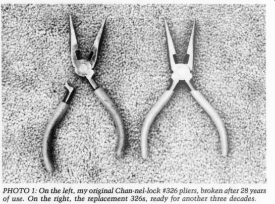
Photo 1 shows the old and the new, side by side. The originals didn't come with rubber insulators on the handles; I put them on myself. Now they're standard equipment.
Quality tools are a great investment for amateurs and professionals alike. As the years pass, you realize they're worth every penny. The new 326s don't operate quite as smoothly as the originals, but then the originals had 28 years to 'break in.' New Stereophile Test CD Readers may recall my review of Stereophile’s first test CD in issue 1/91 (p. 43).
That test disc included a series of low frequency warble tones made with the Old Colony warble tone generator. I noted that the generator was malfunctioning, since the warble frequency was over twice what it should have been. The nominal warble frequency of a correctly operating Old Colony generator is 5Hz, as noted in Stereophile's liner notes. I suggested they repair the malfunctioning generator and include warble tones for the entire audible spectrum.
Shortly after the review was published, Stereophile's editor, John Atkinson, re ported he had measured his Old Colony generator, and verified that the warble frequency was indeed 13.5Hz. However, he said he didn't think the difference was significant. My comments made it into Speaker Builder (6/91, p. 70), which prompted Mr. Atkinson to write a letter to the editor stating that the incorrect warble frequency didn't render the warble tone tracks 'any less suitable for their intended purpose. ” I then ran a comparative in-room measurement using the Stereophile CD and my own Old Colony generator, with the results showing marked differences between the two.
Stereophile has now produced Test CD 2, and the good news is they have repaired their Old Colony generator, and have included the full complement of 1/3-octave warble tones. Although the notes classify them as “subjective room and speaker diagnostic tracks, ” the warble tones can also be used with any high quality measurement microphone to test in-room loudspeaker response, near field response, or 1W/1m frequency response.
Stereophile has also included a variety of other test tones for mostly subjective evaluation of loudspeakers, rooms, CD players and tape recorders. Perhaps the most interesting is the jitter test for CD players. First, a pure 11-kHz tone is played at low volume level. Then, without any announcement, the tone is subject to jitter at the rate of 4kHz. If you can't hear the roughness in reproduction, your CD player is producing enough jitter to mask the differences between the test tones.
Also included are subjective tests for various types of distortion, and a battery of sine tones for checking tape deck alignment, CD player de-emphasis, and noise modulation, as well as a variety of musical tracks. Publisher Larry Archibald's 'Mapping the Soundstage ” track is especially revealing of soundstage localization.
PHOTO 1: On the left, my original Chan-nel-lock #326 pliers, broken after 28 years of use. On the right, the replacement 326s, ready for another three decades.
No test CD would be complete with out channel identification and phasing tests, and Stereophile includes them as well. I highly recommend Test CD 2 which contains most tests, both high tech and unique.
Old Colony carries the disc for $12.95 plus shipping: Old Colony Sound Lab, PO Box 243, Peterborough, NH 03458, (603) 924-6371.
Azimuth Alignment Fred W. Jameson has asked a few questions concerning head alignment of reel to-reel tape recorders, specifically the Revox A77. For the play head azimuth, the service manual suggests making a coarse adjustment by setting the Play back Mode switch to Channel 1, then fine adjustment with the Mode switch set to Mono. The resulting phase errors will be <90°. Strangely, Revox's recommended setting of the Mode switch is different for the record head adjustment:
set the Mode switch to Stereo for the coarse adjustment, and then Mono for the fine adjustment.
Fred wants to know if errors in adjustment which produce phase errors >90° will have any audible effect, and whether these phase errors will affect the bias adjustment. I've performed many head and electronic alignments on a variety of reel-to-reel tape recorders, and the procedures given by various manufacturers often differ, although the end results are invariably the same. I have often found Revox's alignment instructions confusing and unorthodox.
A stereo tape head has a pair of magnetic gaps stacked one atop the other. In order for the two stereo channels to be in phase electrically, the gaps must be precisely perpendicular to the edge of the tape. Professional, full-track alignment tapes are available from most tape recorder manufacturers. They consist of a series of test tones recorded on a reference machine whose record head is known to be in exact alignment.
With the test tape as a reference, begin the azimuth adjustment with the play back head using an oscilloscope and an AC voltmeter for head alignment. The scope produces a Lissajous pattern on the screen, with the left and right tape recorder outputs connected to the X and Y axes, respectively. As the head is rotated from side to side, the two channels move in and out of phase. When the Lissajous hole closes to form a straight line, the two channels are in phase.
The channels can be 360° or 720° out, however, and the Lissajous will show an in-phase condition. Similarly, the channels can be 180° or 540° out, and the Lissajous will show an out-of-phase condition. How can you tell when the difference between the two channels is 0°? Simple. As the head is rotated through various in-and-out-of-phase conditions, the channel levels will reach a peak when the head is aligned correctly. Adjusting the head for proper azimuth re quires monitoring both the amplitude and phase of the two channels.
My approach to coarse and fine adjustment is different from Revox's. I make a coarse adjustment using a 1kHz tone on the alignment tape. Then, [ use a 12 or 15kHz tone on the tape for the fine adjustment. When the AC voltmeter (or the machine's VU meters) indicates maximum level and the Lissajous forms a straight line simultaneously, the heads are in phase. With the Mode switch set to mono, the VU meter levels will reach a peak when the two channels are in phase, but I prefer using a 'scope to see exactly what is going on.
After playback alignment, the play back head serves as a reference for adjusting the record head. You can use a blank reel of tape and record a test tone on both channels, with a Y adaptor on the inputs, if necessary. With the Monitor Switch set to Tape, adjust the record head the same way. Record a 1kHz tone for the coarse adjustment, then switch to 12 or 15kHz for the fine adjustment.
Remember, you are adjusting the record head while monitoring the results on the correctly aligned play head.
Misaligned tape heads result in a substantial degradation of stereo image localization. If the heads misaligned far enough, bass performance will also suffer. At 90° out, you'll hear an effect similar to reversed loudspeaker leads, though not to the same degree.
Reversing the leads on one loud speaker affects all frequencies the same way, and the time relationships aren't altered. With a misaligned tape head, however, the phase difference will vary with frequency. If the heads are 90° out at 1kHz, they will be much further out at high frequencies.
Another complication must be considered. The width of a single track on a two-track stereo tape is just under 1/8 ”.
When the azimuth is misaligned, the 1/8 inch head gap becomes diagonal relative to the tape, rather than perpendicular.
This results in phase differences be tween the top and bottom portions of each head gap. At high frequencies, comb filtering can also result. A 90° tolerance is grossly inadequate, but careful alignment can produce channels as close as 10 or 20° at high frequencies. You really need a 'scope to get alignment this precise.
Bias is the only electrical adjustment which won't be affected by record head azimuth, because it is a record phenomenon and doesn't exist in playback. In correct azimuth in the record or play head will affect equalization and level, but not bias.
Head alignments must be performed first, after which the order of the electrical adjustments is extremely important. Start with playback adjustments beginning with level, and followed by high- and low-frequency equalization.
Record adjustments begin with the erase level, which shouldn't need to be redone unless the erase head is replaced. Bias is next, followed by record level and equalization.
Use the service manual for your recorder as a guide to all adjustments. Several books on sound recording also offer thorough explanations of tape recorder alignment. One of the best is The New Recording Studio Handbook by John M. Woram and Alan P. Kefauver, published by Elar, which I reviewed in TAA 3/91 (p. 56).
CD Servo Reader
Cheng Tan has a question concerning his modified Philips CD-880 CD player. One of the mods is a DC servo, which Mr. Cheng would like to bypass.
He wants to know whether he can defeat the servo when the potential difference between the op amp outputs and ground is 0-V. He would also like to know if the PMI BUF-03 could be used in place of the AD712KNs.
The answer to your first question depends on the resolution of your DC voltmeter. A near-zero reading on the 1V scale of a typical analog VOM is not very useful. To properly check DC offset, you must have a digital DC voltmeter with at least 1mV of resolution. Digital meters with resolutions of 0.1mV are inexpensive, and every serious audio amateur should own one. A CD player's output can be DC coupled to your preamp's in put if the output offset is 5mV or less.
Even offsets as high as 10mV usually aren't a problem, but if it's a true DC de sign, the preamp will amplify the offset.
I doubt that your Philips CD-880 can be operated without either a servo or a coupling capacitor, since the offset from PREVIEW Glass Audio issue 1, 1993
Designing 40W Class A Triode
Overlooked Tube Bargains
Tubesaurus Rex
Resurrection for Lazarus the DAC will usually be too high to al low this. Even trimming won't result in offset that's low or stable enough to allow DC coupling without a servo. I'm not sure why you want to defeat the servo, since it's potentially superior to a coupling capacitor.
The BUF-03s can certainly be used in place of the AD-712KNs, but you'll have to replace the other half of the 712s with a suitable I/V converter chip as well.
Two single op amps can be built up on an 8-pin header to replace a dual op amp, as I described in “POOGE-5, Part II ” (TAA 3/92, p. 34). I still highly recommend the AD-811 as an I/V converter.
Our technique of placing a small coupling cap at the input of the BUF-03 is a trick you may want to consider, but a properly designed servo may still per form better than a coupling capacitor.
Think twice before eliminating it.
Workbook In TAA 3/92 (p. 48), I reviewed Horowitz and Hill's excellent book The Art of Electronics. Reader Ed Aho tells me that Cambridge University Press also publishes a student manual for this book, which he finds a worthwhile accompaniment. The student manual is 614 pages and contains many circuit concepts not discussed in the main text.
Many thanks, Ed! Old Colony will be stocking the work book in the near future. Contact them for details at: PO Box 243, Peterborough, NH 03458, (603) 924-6371.
Electronic Gumshoe
(The following is an addendum to Gary's Ask TAA 2/92 column.-Ed.)
During my investigations, I tried Holco Hd4s and Vishay S102Cs, both noninductive designs. The UK-made Holcos are superior to the Roedersteins, but not as good as the Caddocks. Their sonic performance falls roughly midway between the other two with prices landing be tween 35 and 75 cents apiece (contingent upon quantity and value). When I substituted a pair of Vishay S102C resistors for the Caddocks in my preamp line-stage feedback loop, I did not find the Vishays to be in any way superior to the Caddock MK 132s. Consequently, I must rate the Vishays as excellent, but overpriced.
Holco and Vishay resistors are avail able from: Michael Percy, Audio Consultant, Box 526, Inverness, CA 94937, (415) 669-7181.
Letters
OMISSION
THIS FIGURE WAS inadvertently omitted from Fred Davis' letter in TAA 3/92 ('In Your Ear,’ p. 50).
WHERE THERE'S SMOKE THE LETTERS COLUMN in TAA is a real treat; I am impressed with the quality of information provided and the relent less pursuit of knowledge by the TAA crowd.
Recently, an interesting and an important topic on MOVs used for power line overvoltage protection appeared in TAA.
The concerns the authors have about the use of MOVs are not misplaced; this is a serious subject, and we should take care that we handle it properly.
A recent issue of Electronic Buyers News (# 799, April 13, 1992), includes an interesting article entitled 'Fires Are Blamed on MOVs.’ This article details two cases, a year apart, in which fires are blamed on poorly packaged MOVs.
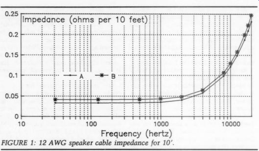
FIGURE 1: 12 AWG speaker cable impedance for 10'.
Both devices are manufactured by the same company but because of pending litigation, the company's name is being withheld.
Louis Shulman, an insurance investigator and a member of an IEEE commit tee, has been reviewing transient surges on AC lines; he and others in the industry believe that MOVs have been misused for years, specifically the 130V device. This is why there is growing sup port to change from the commonly used 130V rated device to that of 150V; this slightly higher rating would increase the MOVs reliability and life expectancy. However, others suggest that the quality of the device is the key issue.
The article also suggests using a fuse to prevent fires, and it briefly discusses the fact that MOVs do wear out-a quite discomforting idea. This is the reason the 150V rating is suggested: it would turn on less often and it would last longer. Each time a MOV is activated, degradation occurs; eventually the MOV will degrade to the point where normal line voltage will turn it on.
Considering all the above, I would recommend buying the GE devices rated at 150V from a vendor such as Newark Electronics; the price is approximately a dollar for either voltage rating. These devices are so closely priced it is crazy not to buy the 150V MOV, but you know how excited some purchasing agents can get over saving a few pennies per device.
However, if there is a sufficient number of transients occurring on the power line, even a quality MOV will eventually fail. So a fuse should be implemented.
The question arises, where is the proper placement for the fuse? I agree with Mr. Dalzell's reply (TAA 3/91, pp. 4-9) indicating the fuse should be placed up stream of both the filter and the MOV protection circuit.
As suggested by Mr. Gergen (TAA 2/91, p. 71), if a fuse is placed in series with the MOV circuit, an indicator should be used to warn the user there is no longer any over-voltage protection available. Even though a fuse can handle five to ten times its current rating during short transients, it will blow during larger ones. So, if a fuse is used in series with the MOV circuit, it should be rated at a value that will survive the expected transients. The fuse should only blow after the MOV fails.
On a related subject, Mr. Hanley's letter (TAA 1/92, p. 60) has provided us with an interesting and creative idea: using a solid state relay as the master switch for line power is not a safe practice. (Using a relay was first suggested in Vern Mastel's article, 'Failsafe Line Protection with Power Pro,' TAA 3/90, p. 26). Line power should always be switched in and out with a mechanical switch! A solid state relay is more apt to fail than a mechanical one, thus keeping the line voltage on the circuit which can be dangerous and a fire hazard.
I would like to offer a new device for consideration. While doing switch-mode power-supply design for use in military airborne avionics, we designed over-voltage protection circuits. We could not, however, use the MOV because of its plastic package and life expectancy. We used a more reliable and sturdy device called a TransZorb; it is a PN junction device rather than a varistor.
The TransZorb is characterized by its extremely fast response time and phenomenal surge handling capabilities. The TransZorb's clamping factor is about 1.2, while the MOV is close to 3; the clamping factor is the ratio of the actual clamping voltage to the rated breakdown volt age at full power. Also the TransZorb does not have the degradation problem from which the MOV suffers.
The schematic symbol for a Trans Zorb looks very much like a zener be cause it operates in much the same way.
Therefore, to use a TransZorb in an AC line, you simply put two in series, cathode-to-cathode or anode-to-anode, or you can purchase the bi-directional package.
If you are interested in more information about TransZorbs, contact General Semiconductor Industries, Inc., (602) 968-3101. I spoke with an engineer there who suggested using their device number 1.5KE220CA to replace the 130V MOV;
the CA represents the bi-directional package.
EDWARD J. AHO Chapel Hill, NC 27573
FIRE PRECAUTION I URGE
John Buschmann to dig out re cent issues of Midnight Engineer and reflect on the possibility of rebuilding his domicile sans fire insurance.
Mr. Buschmann's ill-advised electrical installation (Letters, TAA 1/92, p. 64) is not only dangerous and in violation of the National Electrical Code (NEC) but could give his insurance company an excuse to invoke the ‘‘Electrical Violation ” clause in his home fire/hazard insurance, since the fire would not, in all probability, destroy the 30A breaker illegally installed in his power panel.
The problem with upping the breaker/ fuse size in a misguided attempt to re duce AC line loss, is that you now exceed the fusing point of the line cords used to power the various equipment loads. (Most of today's autos contain “fusible link ” wires.) Mr. Buschmann might try turning off his 30A breaker and plugging in a shorted 18- or 20-gauge line cord into his 30A circuit and then flipping on the breaker. The 20-gauge cord will vaporize and, de pending upon the speed of the breaker, so might the 18-gauge cord. Do not lay the cord on the rug.
Please do not make the mistake of let ting your equipment line cords act as fuses. Under faulty conditions and when not properly protected by proper over current protection devices, they can burn up. Make no mistake about the NEC, you can run size 0 cable to large Russell & Stoll connectors rated at over 150A (REAL) and still fuse/protect the circuit at 15 or 204A, if you so desire. Do ing the opposite will get you into trouble.
On the other hand, the excellent article by Paul Graham is the way to go.
Any computer freak with enough sense to read and understand 'A Centralized Power Conditioner’ (TAA 1/92, p. 32), can well appreciate the advantages of this type of protection. Computer equipment tends to be highly sensitive to power-line disturbances and likes a clean AC line (sine) waveshape.
If you are not qualified, get a good electrician. You are playing with your home and your life here. Just remember the Electric Code is the legal bare minimum. For every safety feature built in to the NEC, some poor soul had a fire Or worse.
DON HELGESON PO Box 3087 Skokie, IL 60067-3087
John Buschmann replies:
Mr. Helgeson seems to be unreasonably concerned about the remote possibility of an internal fault in the line cord itself.
Both my CD player and power amp have their own internal line fuses which would provide protection in case of a power supply circuitry or transformer short. The 30A breaker is correct per the code for the 10/3 wire used up to the outlet. Thus only the line cord from the outlet to the equipment is in danger. It would take some deliberate physical abuse to generate a short in these cords.
I am not staying up nights worrying about the line cord on the CD player vaporizing. The risk of a fault in the line cord has to be orders of magnitude less than the hazards of traffic, smoking, and high blood pressure we face every day without a second thought.
Compliance with the applicable codes is certainly desirable. However, I expect many of the projects built by TAA readers would be frowned upon by UL,
------------
Glad you asked that! Good Idea! You really have some great ideas, so why not share them with your fellow readers? We love to receive typed letters (or even better, a word processor file or output) including clearly written comments and questions. Not everyone's penmanship is easily discernable-please don't make us guess.
If you are responding to a previously published letter or article, please identify it by author; it helps us research and get the answers or comments you seek. In addition, include your full name and address on your letter in case we need to contact you (and your envelope goes south).
Direct your comments, questions, and concerns to Mailbox, The Audio Amateur, PO Box 576, Peterborough, NH 03458-
0576. One more thing. . . include a SASE if you expect a reply.
----------------------------------
NEC, and insurance companies because of components, enclosures, connectors, and construction techniques which have not received the requisite stamp of approval.
(In my view, Mr. Buschmann's comments are not well taken. Line cards age and the cost of proper precautions are too trivial to justify omission.)-Ed.
CHALLENGE MET
I THOUGHT I should let TAA know that Stereophile's John Atkinson took me up on my challenge (TAA 1/92, p. 50). The new copy of their ‘‘Intermezzo ” LP sounded noticeably better than the ones I had previously listened to.
LARRY GLENN; Eau Claire, WI 54701
TILT GRIPE
YOUR SERIES ‘‘Back to the Future' by Williamson and Watling is just what I have been looking for! My heartiest congratulations to Contributing Editor Williamson for pro viding us with this project-it is refreshing to see that he has not been brainwashed by the currently fashion able ‘‘minimalist ” orthodoxy.
I do, however, have a minor gripe: only the values for the ‘‘B ” version with traditional tone controls are given; I'm most interested in the ‘‘tilt ” version.
I have some questions pertaining to the 'A' or “tilt ” version:
1. What are the values for R17 and R18? Neither are listed.
2. What are the values for R32 and R33? Neither are listed.
3. What is the correct value for R16?
It is 51k in the text and in the parts list, but different values are referred to under 'Prototype Measurements.'
BiLL E. BARRY, Tampa, FL 33613
Reg Williamson replies:
Thank you for your kind remarks. Rest assured, that neither Alan nor I will ever allow our brains to be washed by anyone else, let alone corrupted by the views ex pressed frequently in the hi-fi comics.
We do occasionally do it ourselves, though, to rid our gray matter of any possible contamination! Our apologies for the errors that inevitably creep into any technical article.
The whole project (and it still continues) has been an ongoing one for over two years. Alan and I live over 100 miles apart, which is some distance in the UK.
Every idea, change, and modification has to be discussed by phone or letter.
It is usually my fault, since I'm the one who often wants the latest innovation.
Alan is very patient and must despair at times. So occasionally, with our regrets, things do go awry.
Q1: Values for R17 and R18 in both
-------------
PRE-AMP MODULE OP-AMP PC BOARDS
Adapted from latest LT literature. For Phono, Line, Tape, or Headphone Amps. Proven high end performance. Each drilled, 2 3/4 in. x 8 in. board has heavy, tinned traces with:
I Amplifi raining
Selectable feedback circuit Completely Class-A operation Signal, power gnds. Separate
Buffer inside feedback loop Complete parts specs, stuffing diagrams, instructions. SASE for info, or $25 ea. to: Darcy E. Staggs, 3412 E. Maple, Orange, CA 92669
FAX: 714-532-4611
-----------------
Version 'A' and 'B' are simply the feedback chain, so may be chosen for whatever gain you require at this point.
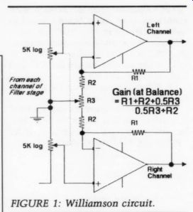
FIGURE 1: Williamson circuit.
The Table 2 reference is of course, in correct. I would suggest initially, a gain of 8.3dB, in which case, R17 should be 8k2 ohm and R18 5k1 ohm. The equation, just as a matter of interest, is 2010g(R17 + R18)/R18.
Q2: Values for R32 and R33 are 5k1 ohm respectively. The gain at center balance of this stage may also be computed with a simple equation (Fig. 1).
Q3: We really fouled this one up, and are very sorry about this. Forget about any mention of R16/116 in the prototype table where reference is made to Input Sensitivity and Input Sensitivity.
It should read R6. Under Output, refer instead to R17/R117 and my answer to Q1.
AN EYE FOR BEADS
I HAVE SUCCESSFULLY built William Chater ’s 40W MOSFET amp ( ‘‘A 40W All-MOSFET Power Amp,” TAA 2/88, p- 7, and 3/88, p. 35). It sounds great and also like a more powerful amp than it is. I have a couple of questions though I read in his discussions in later issues of TAA about ferrite beads on high current wires causing distortion. He claims that none of the beads in his circuit contribute to this phenomenon.
When looking at the schematic, I see beads on the drain of Q12, and on the source of Q11. It appears to me that this is the high-current audio output of the MOS-FET power transistors. The output current then flows through the 0.51 ohm resistors, then through the air core inductor to the speakers. Do these two beads cause distortion? If so, can they be safely removed? My other question relates to the power supply. While testing the amp, I noticed that after turning it off only three of the four 30V mains bleed off and return to ground level. Through diodes D3 and D4, + 30A and + 30B are connected to the 7815; -30B is connected to the 7915 through R7, although - 30A has no path to ground once the amplifier is shut off and will always remain charged to - 30V potential (depending upon the leakage of C2). Will this have any negative effects? In his discussion about MOSFET versus pulse, only one channel gave him trouble with blown transistors at turn on. Could this be a contributor? If so, would it be wise to install a resistor be tween -30A and ground to bleed off the charge when power is removed from the unit?
THOMAS FIGUEIREDO; Woodacre, CA 94973-0683
William Chater replies:
Mr. Figueiredo is correct in asking about the effects of ferrite beads on high-cur rent connections in amplifiers. This question has come up before, and it de serves an answer. My first thought when I was building the amplifier was that an RF bead was a nice simple way of introducing a small inductance, and would add a negligible series potential to the audio output signal; I was wrong. I soon found there was an added harmonic distortion component when even one core was added to the amplifier output lead.
I then replaced that core with the series air-core coil L1 which effectively stabilized the circuit against large load capacitances. But I was unsure about re moving all the beads internal to the amplifier circuit. The source leads and drain leads of each MOS power transistor still deserved to be ‘‘RF-proofed.” Of course, the gate carries no large cur rent, so there was no distortion concern for retaining a bead there. The Q11 drain lead is also tolerant of a bead, since it is tied to the power supply, and is not signal active. That leaves the Q11 source lead and Q12 drain lead to consider.
Tests showed there was absolutely no measurable distortion to be found by adding a bead to these signal points.
This may seem odd at first, since these are active signal points, and not very distant from the speaker terminal at that.
One answer is that these signal points are internal to the overall feedback, and so the effect of a bead might well be reduced by the feedback.
But that still isn't a very appealing design, is it! Why leave anything in the loop that can be a cause of distortion? It might be audible, even if at a low level. I finally came to what I think is a better resolution of this bead effect.
It is the nature of a bead to give rise to a small high-freq. inductive term, coupled with a high-frequency resistive loss term which acts to damp out the unwanted high-frequency abilities of a circuit. Since the bead core material is driven to magnetic saturation by about 1A turn of magnetizing force, there is a nonlinearity at around the 1A turn which can cause the trouble we are describing. While it is true that a core turn which can cause the trouble we are describing. While it is true that a core mounted on the audio output will see no DC component of current, it is also true that a core on the source lead will see only unidirectional currents, since it experiences the current of only one side of the push/pull circuit. I think it might be hard to measure this, but I believe the real reason a core does no harm on a source lead is that it becomes magnetized to the edge of saturation by the first few cycles of audio. After this, the core probably no longer switches be tween its two states, and thus leaves the circuit with only its residual resistive damping term. Perhaps this is the reason I was unable to attribute any problem to leaving cores on the source (or drain) leads. I do appreciate the remaining ‘‘RF proofing ” though, and so I have retained the beads as shown.
With regard to the power supply, Mr. Figueiredo may have something here in his suggestion about the bus voltage discharge rates. I would have no objection at all to adding a resistive bleeder across the -30A supply. It makes sense to bring the power system load into symmetry. I do not have access to the whole story of the failing amplifier, as the in formation as to which channel was the culprit is now only a memory to the owner (not myself, in this case). Still, I did make extensive tests when writing the “MOSFET vs. Pulse” letter (TAA 2/89, p. 46). I think I must have switched that poor amp on and off several thou sand times while recording those wave forms, and if the power supply was going to be the cause of something, I like to think it would have done so then. But you should never say never!
Also see: