THE TURNTABLE CRADLE described here isolates these devices from impulsive shocks such as footfalls, door slams and the like. The design uses commonly available materials and methods, and may be adapted to other devices.
History
Phonograph turntables have long used resilient mounts to absorb shocks and prevent feedback from the speakers. In older (1970s and prior) units this mounting consisted of coil springs supporting the entire upper deck of the turntable.
One of the joys of setting up a new turntable was releasing the transit screws to permit the turntable to float. In the mid-seventies, as turntable design reached its ultimate maturity, many owners were reproducing sound at unheard-of levels, and feedback com plaints were common. The manufacturers changed philosophies. The emphasis shifted from preventing any shocks to selectively filtering out feed back. No longer was the entire upper deck sprung; the turntable and arm assembly had their own subchassis suspension, while a massive base was attached to resilient feet. This cured the feedback problem, but in cheaper turn tables the resilient feet and massive base were missing. Such is the case with the turntable I intended to be my last, a Dual model CS-450. Alas, it was not the sturdy Teutonic Dual of my youth: it used a subchassis, a lightweight particleboard base, and rigid feet. This made it more sensitive to shocks than my venerable BIC-960, which was out of the seven-year spare parts envelope.
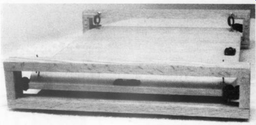
PHOTO 1: The finished cradle.
The dealer examined the suspension and pronounced it healthy, which meant I had to devise some extra shock isolation myself.
Theory Isolation from impulsive shocks is much different, and more difficult, than isolation from feedback. Audio feed back is generally caused by transmission of frequencies from about 100Hz down to whatever lower cut-off the sys tem is capable of. The usual culprit is close proximity of the turntable to the speakers. Less obvious is the fact that flimsy floors, tables and shelves can act like transmission lines to propagate feedback. When feedback occurs, moving the turntable or placing a more massive support under it usually solves the problem.
--------------------
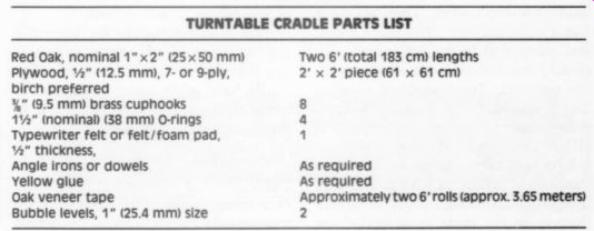
TABLE 1
TURNTABLE CRADLE PARTS LIST
Red Oak, nominal 1 ” x2 ” (25x50 mm)
Plywood, 2 ” (12.5 mm), 7- or 9-ply, birch preferred
3/8 ” (9.5 mm) brass cup-hooks 8
1.5 ” (nominal) (38 mm)
O-rings a Typewriter felt or felt/foam pad, 1 4 ” thickness, Angle irons or dowels
Yellow glue
As required
Oak veneer tape
Approximately two 6' rolls (approx. 3.65 meters)
Bubble levels, 1 ” (25.4 mm) size 2
Two 6' (total 183 cm) lengths 2' x 2' piece (61 x 61cm)
As required
----------------------
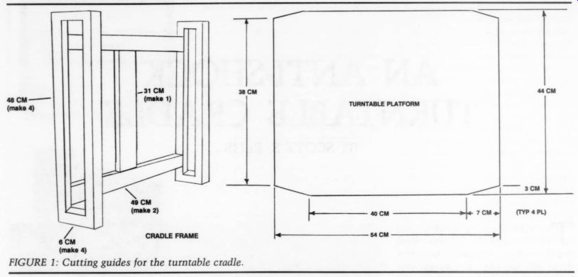
FIGURE 1: Cutting guides for the turntable cradle.
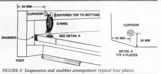
FIGURE 2: Suspension and snubber arrangement typical four places.
---------------
In designing suspensions, it is an easy task to come up with a system which is anti-resonant in the desired stopband.
On the other hand, impulsive shocks, as viewed on a ‘scope, look like narrow pulses of DC. In fact, there is a direct analogy between mechanical suspensions and electrical filters. The modeling techniques are the same. Stopping impulsive shocks is much like blocking DC in a circuit; a capacitance in series is required.
In mechanical terms, this series capacitance must take the form of an element which will absorb the impulse and then dissipate it as heat. By this definition, we really require a mechanical resistance so great that it totally ‘drops’ the voltage (impulse) across it.
It would be easy to jump to the conclusion that all we need is a great deal of mass as our resistor, but not so fast.
Most people use their turntables on a table or shelf. Putting a large weight on such a support creates another weighted lever with its own series of resonant modes. Of course, a separate stand, suit ably weighted, can also be used; I am reminded of the hi-fi pioneer who in 1946 perched his 78 rpm turntable atop 600 lbs. of sand.
A workable solution is to provide a very lossy path for impulses. This path must not introduce any resonances of its own. For this reason, coil springs alone just don't work. They act more like a pure reactance. Too stiff a spring and there will be no deflection, efficiently transmitting the shock up to the tonearm. Too compliant a spring and the mass of the turntable will oscillate easily, bounding up, down, and all around. It's for these reasons that auto suspensions use shock absorbers (resistance) paralleled with coil springs (reactance). Although shock absorbers (known in the trade as dashpots are available in sizes suitable for a turn table, they tend to be expensive and hard to find. In thinking through this problem, another solution popped up out of the dim past.
Chain Gang
Some years ago, an acquaintance of mine had suspended his AR turntable from chains hanging from the ceiling.
In most homes, that's undesirable, but it inspired me to design and build a cradle that offers most of the advantages of the ceiling chains (Photo 1).
This cradle suspends the turntable platform from folded O-rings, and snubs any lateral motion with thick felt. The cradle base offers some resistance by virtue of mass, but not so much as to flex a typical stereo table.
Construction
I dimensioned this project metrically even though some of the parts came dimensioned in English units. I've found that this makes for greater accuracy. Most amateur craftsmen (myself included) tend to let the smallest unit of measure drift away. A millimeter lost (or gained) is less trouble than 1/16 ”, and easier to count on a ruler.
I fashioned the cradle frame from 1.5 ” (38mm)-wide, 3/4 ” (19mm)-thick red oak strips, usually sold as nominal 2 ” (50mm) width, 1 ” (25mm) thickness, for flooring. Figure 1 gives the cutting guides for the wooden parts. The turntable sits on a platform of 0.5 ” (12.5mm) plywood which is suspended by 1.75 ” (38 mm) O-rings, folded double and stretched between cup hooks (Fig. 2) from the inner sides of the base. Felt snubbers sit inside each corner to pre- vent excessive lateral motion in severe cases. Figure 2 also shows the locating dimensions for the cup-hooks.
My cradle was assembled with yellow glue and angle irons, although dowels are better if you have a drill press.
The ends of the cradle frame are covered with veneer tape. The oak parts were finished by scraping with a single edged razor blade, following the grain.
I then gave the smoothed oak a coat of paste wax and buffed it.
The snubbers are made from leftover pieces of a felt/foam typewriter pad, used previously for speaker grilles. The snubbers should just fit between the insides of the cradle and the platform corners.
Four feet, 1.5” (38mm) x 3” (76mm) were cut from the same felt/foam type writer pad and glued to the underside of the cradle, where the two 49 cm lateral braces join the ends.
I fastened small bubble levels in the centers of the front and left sides of the platform. After the turntable is set upon the platform, allow the O-rings about three days to assume their appropriate elongation. After this time, the plat form should be quite close to level. If additional leveling is required, self adhesive cardboard or felt shims can be attached to the feet. Naturally, the level of the turntable, as measured on the platter, should be checked also.
Performance
The cradle really does reduce wow and mistracking due to shock from footfalls and door slams. Of course, no cradle can compensate for a flimsy table and/or floor structure. Nor can the cradle absorb shocks beyond a certain magnitude. Other devices, such as tape decks and compact disc players, can also benefit from a cradle of this type.
-----------------------------
About the Author
A prior professional incarnation, and has been building audio devices for 20 years.
-------
Also see:
HIGH-QUALITY AM FROM A CRYSTAL RADIO