By RMB
This article describes a new I approach for analyzing the dynamic range of the phonographic playback system, in which the cartridge and preamplifier are treated as an integrated system. I analyzed the dynamic range potential of several combinations of phono cartridges and preamplifier amplifying devices and compared the results to CDs.
Additionally, I speculate about the drawbacks of frequency domain characterizations of musical audio components and suggest that the time domain may be a more natural frame of reference for audio instrumentation development.
Introduction
Why should anyone still be interested in the analog phonograph? The reason is simple: today's best record playback systems sound better than today's best CD players. (CD playback is improving, though maybe not faster than turntable, arm, and phono cartridge developments.) Moreover, many analog record treasures are unavailable on CDs or other available and anticipated digital music sources.
After all, standards to transmit digital music (and video) directly to our homes are developing. This will open a vast library of musical selections for our potential enjoyment.
I believe that commercial considerations and the limitations of today's digital technology will establish digital transmission standards of even lower quality than our current CD standards.
Unless these standards are dramatically upgraded (in terms of information content), we may never have a source of music for our homes that sounds better than the phonograph.
Are analog records inherently better in some sense? Your ears may already be telling you that analog can sound better than today's digital. I will provide quantitative reasons this may be so.
Qualitative Requirements
The subtlety of detail in the grooves of an LP record is astounding. Quiet, yet clearly audible, details (such as the reverberation characteristic of Carnegie Hall) are represented by stylus motions of less than an ultraviolet wavelength (1/100,000,000 of a meter)--a dimension approaching the size of a complex organic molecule.
This submicroscopic motion may be superimposed on an orchestral crescendo involving stylus motions thousands of times larger. Over the last ten years, the ability of modern cartridges, arms, and turntables to resolve this ultra-fine detail, particularly during loud and complex music peaks, continues to improve beyond all expectations.
Ideally, to reproduce the dynamic range inherent in the groove modulation of a fine LP with the least possible degradation, the background noise added to the quietest passages by the cartridge-preamplifier combination should be essentially inaudible.
Similarly, the cartridge-preamp system should be able to clearly reproduce the loudest sounds on record without distortion, compression, or clipping.
The same should be true of CD playback. The quietest passages should be reproduced without added noise or distortion of the music caused by amplitude steps, or sampling intervals that are too coarse, or by filter phase shifts and ringing. The loudest peaks encoded, as for analog records, must be reproduced without distortions, compression, or clipping.
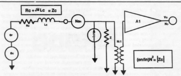
FIGURE 1: Simplified noise model of phono cartridge and preamplifier.
Definitions
For CD players, dynamic range is essentially the ratio of the loudest possible output signal to the quantization noise, i.e., the noise corresponding to the round-off error of the least significant bit. For the 16-bit standard CD format, this is 96dB dynamic range.
To parallel the previous CD definition, I define the dynamic range of a phono cartridge as the ratio of the loudest sound to the background noise referenced to the preamp output terminals. Crucial to this definition is understanding that there is an intimate relationship between the cartridge and the first preamplifier stage.
Each interacts with the other to establish dynamic range; neither the cartridge nor the preamplifier stand alone.
Oddly enough, the preceding definition is not the conventional one, which is simply signal-to-noise ratio (S/N) at some arbitrary cartridge output level well below the loudest.
Often, preamplifier noise is characterized with the input shorted, which, as you will see, is an incomplete and useless way to measure preamplifier noise. This conventional definition led to the widespread notion that phono dynamic range is only 60-70dB. If true, this means LPs are about 25-35dB more compressed than CDs, an amount of compression so severe that you would notice a real "Muzak"-like loss of dynamic impact in LPs relative to CDs.
In fact, serious listeners find the opposite is true. Using LP and CD issues of the same performance, they have carefully and empirically compared state-of-the-art (SOA) phono playback systems to SOA CD players.
LP playback is generally considered either better or equal to CDs in macro dynamic impact. LPs are usually superior in subtle micro-dynamic shadings.
Examples
To help quantify dynamic range for real phono playback systems, I use three modestly priced examples: a Sumiko Blue Point, a high-output moving coil; a Grado MCZ, a fixed coil with moving magnet; and an Ortofon MC 100, a very low output moving coil. Although better-sounding cartridges are available, I chose these for modest price and convenience, not to mention that I own one of each.
To estimate the dynamic range capability of the vinyl LP, first establish the cartridges' sensitivity and the largest signal amplitude it must handle. The sensitivity figures in units of mV/cm/s are: Blue Point, 0.85; MCZ, 0.42; and MC 100, 0.018. The worst case (loudest) recorded sound on a record in the literature is 105 cm/s at 7kHz.! Of these three cartridges, the largest signal available to the input of the preamp is 0.85mV/cm/s x 105cm/s, or 89mV. This establishes the upper limit of dynamic range required of the preamp for the Blue Point cartridge.
From a design point of view, the pre-amp should cleanly handle an input signal of at least 89mV at 7kHz.
Noise Analysis
Calculating the equivalent preamp input noise is a bit more complicated. The input noise depends on the noise parameters of the preamplifier and the equivalent circuit parameters of the cartridge. For the above three cartridges, the significant circuit parameters are the series resistance and inductance. The values are: Blue Point 108 ohm, 190 uH; MCZ 70 ohm, 9mH; and MC 100 3 ohm, negligible inductance.
None of the manufacturers states a need for a loading capacitor. Small loading capacitors and cable capacitance and inductance have a second order effect on the equivalent electrical noise anyway, so I neglected them in the following analysis.
Figure 1 shows a simplified equivalent circuit for analyzing the noise performance of a phono cartridge and preamplifier, or pre-preamplifier. The circuit model is based on the Rothe Dahlke theory of noisy four poles (in which the preamplifier has one input port and one output port). In this model, amplifier noise originates, at audio frequencies, as two uncorrelated generators: an ideal noise voltage generator, ey, and an ideal noise current generator, iy. These generators interact with the cartridge impedance to establish the basic noise level of the phono playback system.
The figure includes a transformer to show the effects of coupling very low output moving coil cartridges to pre amplifiers. You assume the trans former is ideal, but you can represent its losses by increasing the power of the preamplifier noise generators. To apply the diagram to transformerless preamplifiers, simply set N, the turns ratio, to one.
To calculate the S/N ratio at the preamplifier output, first calculate the desired output signal as follows:

... where: Vo is the desired output signal in volts;
ec is the open circuit output voltage of the cartridge in volts;
N is the turns ratio of the coupling transformer;
Z is the input impedance of the amplifier in ohms;
Z: is the series impedance of the cartridge, R- + jX(, in ohms;
A, is the voltage gain of the preamplifier.
The output noise is:
... where: eg is the thermal noise voltage of the cartridge resistance in volts;
ey is the equivalent input RMS voltage noise generator of the preamplifier in volts;
iy; is the equivalent input RMS current noise generator of the preamplifier in amps.
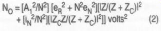
The output S/N ratio is (1) divided by (2):
VON, = e2lleg? + Nog? + [iy IN?[IZ 12] 3)
Notice that the input impedance of the preamplifier has dropped out, and, therefore, does not directly affect the S/N ratio.
Shunt resistances placed across the preamplifier input increase the noise power of the voltage and/or current generators. Such resistors can only decrease dynamic range by increasing noise. Motchenbacher and Fitchen show that the output S/N ratio is maximized if the following is true:
N[ey/iy] = 1Z.| ohms (4)
Substituting (4) into (3) and simplifying yields:
Assuming optimum noise coupling, the output noise is dependent on the product of the basic noise generators of the preamplifier and the magnitude of the cartridge impedance. Equation (5) shows that the preamp's eNiN parameter is useful for choosing a low-noise preamplifier; the lower ein the greater the potential S/N.
Therefore, consider using eNiN; as an appropriate figure for any amplifying device in which low noise is important. I find it more useful than noise figure because the parameter contains information necessary to noise-match to a source and compare two devices.
Of course, as with noise figure, eNiN varies with frequency, bias current, temperature, and even signal level.
For my calculations, I account for variations in frequency by breaking the frequency band into small segments and assume typical bias currents and temperatures.
Noise Matching
For a low-output moving coil cartridge, the source impedance is very small, for example, 3 ohm resistive for the MC 100. For such resistances, it is important to make ey; small compared with the equivalent noise voltage of the source. Nyquist showed that the RMS noise voltage of a resistor is:
eg = [4KTBR] ^1/2 volts (6)
where: k is Boltzmann's constant, 1.38 x 10 2 W-s/°K;
T is the resistor temperature in degrees Kelvin;
B is the noise bandwidth of the measuring system in hertz;
R is the value of the resistor in ohms.
For a 3 ohm resistor, eg is 0.24nV /Hz.
Typically, the ey for a good low-noise amplifier is 1-5nV/Hz, about ten times greater. Connecting the MC 100 to a typical preamplifier results in a poor S/N ratio. To match a low-noise amplifier (for example, an NE5534 op amp) to the MC 100 using equation (4), a transformer with turns ratio N is required, where N is given by:
= [Reiy/ey] ^1/2 7
... and Rc is the equivalent resistance of the cartridge in ohms.
For an NE5534, iy is 0.4pA/Hz ^1/2 and ey is 4nV/Hz ^1/2. Thus, the N required is 1:63. The message here is to design the transformer needed to match a low-output moving coil cartridge to a preamp as a noise-matching device, not as a voltage step-up transformer.
If transformers are a problem, try another way to improve the S/N ratio for small source resistance: paralleling input devices. Motchenbacher shows that ey, improves by the square root of the number of parallel devices and that iy, worsens by the same factor.
Thus, for P parallel devices, the opti mum source resistance is:
Roe = e_N/P_in Ohms (8)
For the 5534 op amp, the optimum source resistance is 10k ohm. Thus, you need 3333 op amps to match to the 3 ohm source resistance of the MC 100, which is an impractical solution. On the other hand, some FETs and bipolar transistors have an ey; of less than InV/Hz^1/2.
Paralleling eight or more of these devices can yield an ey; comparable to a 3 ohm resistor. While not optimum, this is a far more practical approach and produces good dynamic range.
Preamp Topology
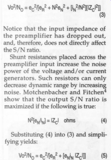
To analyze a preamplifier's dynamic range, we must know its topology. The topology I chose is shown in Fig. 2.
In this circuit, the RIAA network is broken into two sections, each of which, in turn, is driven by a separate amplifier. The first section has a nominal breakpoint at 50Hz and a nominal turnover" frequency at 500Hz. The second section has a turnover frequency of 2,120Hz.
FIGURE 2: Preamplifier topology.
You can achieve exact RIAA compensation in this configuration by adjusting or trimming the components in each section. Amplifiers with assumed low reverse gain isolate the sections of the RIAA network from each other, so little interaction occurs between the upper and lower turn over frequencies. Additionally, you can adjust the value of the capacitor in the 2,120Hz network to compensate for loading introduced by the cable and the line amplifier.
Applying the Theory
If you know the topology and noise equivalent circuits of the preamplifier, you can analyze the dynamic range of various combinations of cartridges and preamplifiers.
The first amp should determine the noise. However, the maximum signal handling capability is a function of both amplifier stages and the cartridge.
Based on the maximum recorded music levels on records at six selected frequencies, I calculated the maximum gain for each stage assuming that the amplifiers could swing through 10V RMS without compression.
Table 1 shows the results of the analysis in spreadsheet form. Note that each cartridge demands a differ ent gain setting because of the differences in cartridge sensitivity. In any case, the 7kHz signal dictates the maximum input signal handling requirements of both stages. However, because the RIAA network following the second stage rolls off higher frequencies, the 3kHz signal emerges as the largest output signal.
To compare the dynamic range capability of records to CDs, think of the 3kHz signal as the maximum digital signal that a CD can handle, i.e., 16 ones. Next, you need to know how the preamplifier and cartridge thermal noise compares to the digital quantization noise.
Quantization noise for an ideal 16 bit CD is easy to calculate. It's simply 20 x log (2'%), which is 96dB down from the maximum signal. Calculating the thermal noise of a preamplifier and phono cartridge is a little more complex.
I used equations (1) through (8) to analyze the noise power at the output of the preamp, and chose eight different devices as the noise-determining front end of the first stage: an FET designated C413N, eight 2N4403 transistors in parallel, and opamps 5534, TLE2037A, HA5190, OP44, OPA604, and AD797. Next, using equation (7) to determine the optimum noise matching transformer, I calculated the optimum noise performance achievable with each of the devices as driven by each of the three cartridges. Finally, I calculated the ratio of the maximum output signal to the noise power to determine the dynamic range of each of the 24 combinations.
Table 2 shows a sample portion of one of the sets of calculations. (I would not attempt these calculations without a spreadsheet; the calculations require 40 pages.) I broke the 20Hz-20kHz audio bandwidth into ten one-octave bands centered on frequencies as shown in column E, thus taking into account the changes in ey, and iy; and the impedance of the cartridge as frequency changes. I calculated the noise as a voltage squared in each frequency band and then added the squared voltages to arrive at an integrated noise level for the 20-20kHz frequency band.
Following each stage, the RIAA net work will equally attenuate the signal and noise. As long as the second-stage noise is low compared to the attenuated first-stage noise, the dynamic range is not changed significantly.
(The gains shown in Table 1 are more than adequate to assure that second stage noise is negligible.) Figures 3a and 3b summarize the results of the spreadsheet calculations.
LP vs CD Dynamic Range
The vertical bars in Figs. 3a and 3b represent the dynamic range obtain able with various combinations of cartridges and preamplifier devices. The line marked with squares represents the optimum dynamic range attain able with an ideal noise-matching transformer. Ideal means it adds no additional noise and varies its turns ratio to match the ratio eN /iN as a function of frequency. Figure 3a arranges the preamps in descending order of their eNiN; product, while Fig. 3b shows the preamps in descending order of their noise voltage generators, ey.
For the high-output cartridges, the Sumiko Blue Point and the Grado MCZ, the dynamic range possible with good low-noise devices, such as the C413N or AD797, is almost optimum. For the low-output moving coil cartridge, the MC 100, the dynamic range approaches within 3.5dB of optimum for a preamp with eight 2N4403 transistors in parallel. Most importantly, the dynamic range potential of any of the three cartridges with its best preamp is equal to or better than the theoretical best a CD can achieve! The best of these modest cartridge-preamp combinations has 16dB better dynamic range than the CD upper limit.
The best transformerless combination, the Sumiko and eight parallel 2N4403s, has greater than 112dB dynamic range, and is only 1.5dB shy of the optimum combination of a Sumiko with a transformer and a C413N FET. At 111dB, the Sumiko/ AD797 combination is only 1.7dB less than optimum.
In Fig. 3a the trend in optimum dynamic range performance for any of the cartridges follows the trend in the eNiN product. Interestingly, the optimum dynamic range is very nearly the same for all of the devices except for the HA5190. This means that cartridge noise generators tend to dominate this set of optimally noise matched phono preamps. However, for non-optimum cases, the trend is not so straightforward.
The ey /iy ratio interacting with the cartridge impedance determines which is the best combination. For example, for the Sumiko and Ortofon cartridges, the parallel combination of 2N4403s is best (highest dynamic range), while the C413N is best for the Grado. The larger impedance of the Grado cartridge favors those preamps with lower iy.
In Fig. 3b, where the data is arranged in order of descending ey, the dynamic range of the relatively low-impedance moving coil cartridges, the Sumiko and Ortofon, follows the trend in ey. The Grado, because of its significantly greater impedance, does not always follow the ey; trend.
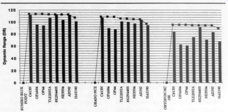
FIGURE 3a: Preamps arranged in descending order of eN iN.
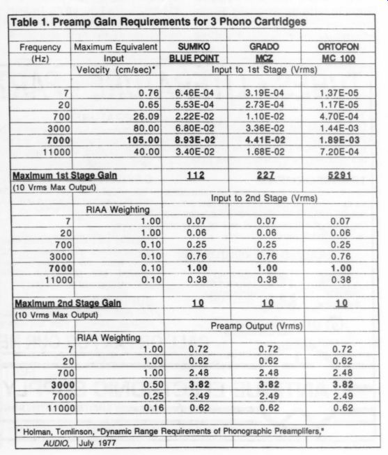
Table 1. Preamp Gain Requirements for 3 Phono Cartridges
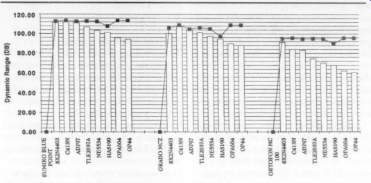
FIGURE 3b: Preamps arranged in descending order of e_N
The bottom line here is that if your goal is to achieve best dynamic range, select the preamp and cartridge with knowledge of all the relevant parameters. Audio amateurs can do this during the design phase. Preamplifier, low-output transformer, and cartridge manufacturers should at least state their products" parameters so you can make intelligent choices. Of course, I am not suggesting that we choose components on these parameters alone.
Beyond the Numbers
When comparing the sound of phono playback with digital, note the difference in the way noise combines with the signal and how humans react to that noise. Phonograph thermal noise is linearly added to the signal. Thus, the right kind of filter can retrieve signals below the noise level. Our ears are the right kind of filter. We can retrieve musical signals that are 10-30dB below the thermal noise (or tape hiss). You can decide if this factor adds an additional 10-30dB to the maximum dynamic range for LPs I previously calculated.
No doubt, we can more readily hear music embedded in thermal noise than in quantization noise. Why?
Digital noise destroys information, whereas thermal noise adds innocuous, unrelated information to music.
Ironically, despite the low noise usually attributed to digital, quieter passages of records sound better than their digital counterparts. The greater dynamic range potential, and the ability to hear music well below analog noise, and digital's quantization distortion of quiet sound all partly explain why I, and perhaps you, still prefer the best phono playback systems to their digital counterparts.
Epilogue
The intent of this article is to demonstrate that the LP is, contrary to popular belief and the opinion of the audio vanguard press, potentially superior to the CD in dynamic range. I used a rigorous, analytic approach to do this. I take little comfort in the results of the analysis because numbers rarely tell us much about how audio components sound. In this case they seem to sup port what I already believe to be true.
The following comments, although speculative, support the notion that we have much to learn about how humans perceive music. An understanding of this process will help us to identify the significant parameters for audio reproduction systems and to develop techniques for measuring them.
Myth of the Frequency Domain
Literature suggests that perfect play back is possible if we could only reduce measured distortion and noise to inaudible levels. Up to this point, I focused on noise and dynamic range.
For the digital case, the term quantization distortion is more appropriate than noise, since quantization is essentially a nonlinear process.
We generally consider nonlinear distortion as harmonic and intermodulation distortion, which we measure in the frequency domain, and use sinusoids as the test signals. Almost all of our audio equipment is characterized in the frequency domain. Yet modern sensory research suggests that our ears are not Fourier analyzers, decomposing music into sinusoidal components. At least for music our cars seem to be very sensitive, perhaps most sensitive, to distortions in the time domain. We hear live music and listen to recorded music in the time domain; i.e., we process variations in air pressure as a function of time, and do not receive or perceive music in the frequency domain.
I believe fidelity in the time domain is paramount. Consider that great orchestra leaders breathe life into music by controlling the flow of the music in the time domain, i.e., by making adjustments in tempi and loud ness. Not much training is required to hear differences between first- and third-rate orchestra conductors.
This, of course, doesn't prove my time-domain hypothesis. It does underscore the idea that our hearing mechanisms are highly sensitive in the time domain. We can reasonably assume that similar perceptual mechanisms are at play when we perceive that something is not quite right with today's digital music, and that digital is doing something wrong in the time domain. We know that major improvements in digital happen when time-domain jitter is reduced, but there is something more fundamentally wrong with digital.
The Trouble with CD Sound
To quote from an article by Fonte [6]: "It is a mystery to me how basic concepts can get so twisted around that they become nearly meaningless. In this new world of digital sampling systems, you would think that the Nyquist theorem would be as familiar as Ohm's law. Nevertheless, as time passes, I see more people and publications misunderstand its implications.
The results of these misunderstandings are circuits that don't work well and designs that are inappropriate... Simply stated, the Nyquist theorem tells you the minimum sampling rate needed to reconstruct a signal's frequency without aliasing." The theorem fails to directly mention recovering the phase or amplitude of the signal. If the sampled signal has a sinusoidal shape and also repeats for several cycles, phase and amplitude errors will decrease to small values. However, if the signal to be digitized is impulsive and does not contain many identical repeats, then significant errors in phase and amplitude can occur. Errors in the frequency domain can also occur for non repetitive sinusoids.
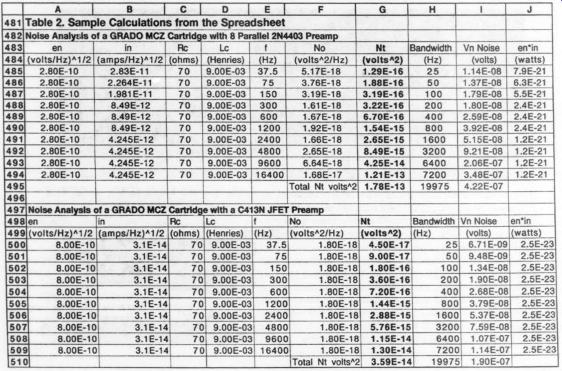
TABLE 2
Fonte shows that time-domain errors are inversely proportional to the sampling rate and can be quite significant. He states that CDs can introduce amplitude modulation errors to 30%, amplitude errors of 0.436-1.84dB, and frequency errors up to 18% into single cycle events corresponding to the harmonics of instruments. He gives sever al arguments explaining why the ear does not hear these aberrations in CDs:
- distorted harmonics are over whelmed by the strength of the fundamental;
- the ear cannot hear an error of 0.436dB;
- the ear is not sensitive to phase errors in music signals;
- music signals, consisting of many repetitions of the same waveshape, average out any of these aberrations to zero.
While I respect Fonte's analysis, | disagree with his assumption that CDs sound great, and that the ear does not hear the rather large errors he ascribes to the CD sampling process. On the contrary, I think Fonte has put his finger on one of the fundamental problems with CD sound: time (and frequency) domain errors inherent in the sampling process.
That notwithstanding, if the time domain is important, shouldn’t we be able to characterize our audio components in the frequency domain and then Fourier transform to predict their behavior in the time domain? Another Theorem Superposition' is the basis of Fourier theory; i.e., the theory states that there is a weighted set (an infinite set in the case of nonperiodic waveforms) of sinusoids, which, when linearly added together, can represent complex wave forms. But superposition only holds in the case of linear systems. Of course, we know our systems are very nonlinear.
As such, we cannot validly use Fourier transforms to relate a characterization in one domain to the other.
When I see music in the time domain (at the output of an audio component on an oscilloscope), I do not see sinusoids, but rather non-symmetrical and strikingly impulsive looking shapes highly correlated in time. I suspect that sinusoidally stimulated harmonic and intermodulation characterizations tell us little about what we hear in the time domain.
In the absence of test equipment we use our ears. Stories about tie analog version of a performance sounding better than the digital are not unique, for they have been reported repeatedly in audio publications emphasizing listening comparisons. Keep in mind these comparisons are for a digital playback system, which should certainly sound better because its frequency domain distortion measures 90dB below the maximum signal. In contrast, the cartridge component of the analog playback system measures somewhere between 30-60dB for sinusoidal references. Clearly, frequency domain distortion measurements are meaningless for predicting which audio components will sound better than others.
We need to understand in more detail, and perhaps fundamentally, how humans perceive and enjoy music. I predict that time-domain measurements will be crucial and frequency domain much less so. Re search that develops a set of test techniques more closely related to how the ear perceives music could well lead to revolutionary time-domain instrumentation breakthroughs.
All Noise Is Not Created Equal
In my earlier quantification, I went along with the common notion that a single-dimensional parameter that is the same for both recording techniques represents LP and CD noise.
This is wrong for several reasons:
1. Digital quantization noise sounds-and is-completely different than analog thermal or record surface noise (or analog tape hiss).
2. Within the class of analog "thermal-like" noises of equal power, major differences exist in how annoying they sound.
3. There is good reason to believe that not all quantization noises, even at equal 16 (or n) bit resolution level, are or sound the same; e.g., D/A converters using different roundoff algorithms sound different.
To expand on these very fundamental differences, note that random analog noise, uncorrelated with the music, operates as another signal linearly adding to the music signal. A signal with amplitude less than the noise is preserved and amplified just as accurately as a signal larger than the noise. Thus, the ear can filter out weaker music from noise.
The effect of digital quantization noise is entirely different and quite nonlinear. As signals grow progressively smaller (relative to the maximum signal level the A/D converter can handle), fewer quantizing bits are available to resolve them and smaller signals thus become progressively more distorted by the A/D process. A limit is finally reached where signals smaller than the smallest quantization step are completely lost.
The A/D process sets all such signals to a fixed amplitude. There is no music signal for the ear to filter out of the quantization noise. I believe the facts that the ear filters weak music from noise and smaller amplitude signals amplify just as accurately as large are important advantages of analog over digital. (Some of this advantage can be lost where Class B or starved AB analog amplifiers, such as many op amps, are used because they distort smaller signals.) Of course, some analog noises are not "thermal-like" and are quite important in audio.
1. Record pops and clicks, due to dirt or scratches. The effect of these on music is not linear and additive.
Instead, the effect appears to be a kind of burst distortion, perhaps analogous to slew rate limiting because of the steep scratch edge the stylus meets.
Clearly, in general, better-sounding turntables audibly reduce the annoying quality of pops and clicks both with respect to the ear's perception of the intensity of the initial distortion transient and the ringing thereafter.
2. "Popcorn" noise associated with a number of op amps. Unlike the hissy noise we find easy to filter music through, "popcorn" noise increases in power with lower frequencies and occurs in fractional second bursts.
This adds a gravelly, grungy sound, particularly at low frequencies.
3. "Contact" noise typically associated with dirty contacts and poor connections, or sometimes associated with stranded wire in the signal path.
This nonlinear noise imparts a digital character to analog sound or makes digital sound even drier and more etched. Others hypothesize that the nonlinear effect on music is the result of partially shorted point-contact diodes at the junction between dissimilar materials, e.g., copper and copper oxide or nickel and nickel oxide.
These diodes are highly nonlinear components which severely distort low-level music. Distorted low-level musical details submersed within more faithful high-level music give "contact" noise a digital character.
Noisy LPs
Scratched or dirty records are noisy. A good record vacuuming system greatly reduces this noise. SOA cartridges, arms, and turntables also reduce, by a surprising degree, the audibility of dirt and scratch effects. However, even a pristine LP can still emit hiss from the master tape and/or record surface noise.
Tape hiss can be largely eliminated by noise reduction processing (at the expense of a small loss in overall fidelity) or by recording at higher levels (at the risk of compressing loud transients). At least 10dB of hiss reduction is possible with either technique.
When audible surface noise occurs, it is due to indifference on the part of the recording industry-poor-quality vinyl or poor-quality stampers at the pressing plant. Lack of quality control is abetted by the RIAA record industry standard permitting surface noise of 55dB below a 1kHz sinusoid recorded at 7cm/s (interpolating from the Maximum Equivalent Input Velocity column of Table 1, the equivalent RIAA dynamic range is roughly 67dB at 1kHz).
The above notwithstanding, clean, unscratched, good quality records played back through "first-rate" modern cartridges, arms, and turntables sound as quiet as CDs to me. More importantly, I find well-recorded LPs more dimensional, truer to the tonal qualities and dynamics of live music, and very noticeably more relaxing than CDs, particularly during long listening sessions. Additionally, my guests, most of whom are not audiophiles, listen to the same source material played back from LP and CD, and prefer the analog version without exception, much to their great surprise! direct-to-disc method) should easily achieve greater dynamic range than the playback system. Whether analog tape recording, which is the source of most of our LPs and some of our best CDs, can achieve greater dynamic range than CDs or LPs needs to be evaluated using the methods of this article.
Fortunately, there seems to be a rekindled consumer interest in vinyl. I hope that if this trend continues, and affordable analog records become available again, the recording industry will produce a quality record, free of surface noise and warps, that exploits the full dynamic range potential of the phonograph. (We know much bad vinyl was produced, especially near the end of the LP era, somewhere in the '80s, when it seemed that overnight all vinyl had been yanked out of record stores and replaced by CDs and cassettes. During this period, I remember trying four or more warped records until I found one that played. Consumers with similar experiences must have been happy to see vinyl go away.) Having said few nice things about digital in this article, I must point out that I have great expectations. I prefer the convenience and ruggedness of CDs, and hope that over time their quality achieves or surpasses analog. I find it ironic that with all the technology advances over the past 40 years, analog tape recorders and records of the fifties can achieve a higher standard of musical fidelity than today's technology.
But we understand a good deal more about CDs' limitations, and technology has advanced since the 16 bit/41kHz standard was established.
Affordable 20-bit A/D and D/A technology is here. Those few who have heard 20-bit digital attest to a sound closer to analog masters (if also played back at 20 bits).
To achieve analog quality, however, digital standards need raising to per haps 21 or more bits. Also, sampling rates must be significantly raised.
(The CD standard sampling rate of just over twice the highest frequency humans are reputed to be able to hear (i.e., 20kHz) is suspect. A growing body of evidence suggests we can hear rates of change in time-domain signals that are greater than equivalent slopes for 20kHz sine waves.) Most importantly, the sampling rate and quantization levels should match our ears' demand for fidelity in the time domain.
Sooner or later the 16-bit/41kHz standard will be revisited, if for no other reason than to produce a small but truly state-of-the-art music sub-industry. I hope the next digital standard is carefully and deliberately set much higher than our de facto analog standard of 40 years ago.
------------
ACKNOWLEDGMENT
Thanks to Dr. Pierre M. Sprey for many helpful suggestions on organizing the manuscript.
REFERENCES
1. T. Holman, " Dynamic Range Requirements of Phonographic Preamplifiers," Audio (July 1977).
2. Data provided by Mr. Matthews at Sumiko.
3. H. Rothe and W. Dahlke, "Theory of Noisy Fourpoles," Proc. IRE 44, 88811-818 (June 1956).
4. C.D. Motchenbacher and F.C. Fitchen, Low Noise Electronic Design (John Wiley, 1973).
5. "Audio Handbook," National Semiconductor Corp.
(1976): 2-27.
6. G.C.A. Fonte, "Apply fundamentals to avoid surprises with sampled systems," EDN (June 24, 1993).
7. S. Stein and J.J. Jones, Modern Communication Principles (McGraw-Hill, 1967).
------------
------
ABOUT THE AUTHOR:
RB received his BSEE from Lehigh University. He is founder and owner of in Sound, which produces high end audio amps, preamps, and, in partnership with Mapleshade Electronics, the Omega Mikro line of digital and analog interconnect, power, and speaker cables. Ron also specializes in personal and meteor burst communication systems design. With his wife Marcia, he is raising his sons Marcus and Mitchell. His hobbies include music, beer-making, flying, and restoring old Volvos.
--------
Also see:
A Filter For Treble Distortion In Recordings