Can't live with the distortion on some recordings? Try this DIY filter to restore listening enjoyment.
here is consensus among music lovers that the most common type of distortion in recorded music takes place between 2k and 3kHz. At those frequencies there is often an amplitude rise from a few decibels into the double figures. When severe, there is nothing subtle about it. The abrupt step up in volume appears to disrupt the normal, orderly procession of the harmonics. The ear experiences this as distortion that can make a recording intolerable. It is responsible for the grating whistle that replaces the violins' high notes and for a soprano voice that becomes a screech.
Very few listeners can ignore it, be cause the distortion occurs in the frequency area where experience shows (and the psycho-acousticians confirm) that the ear is most sensitive, where a change of as little as 0.5dB can be perceived. Sensitivity decreases sharply with decreasing frequency. The distortion was obtrusive on many LPs, even prestigious ones. For example, Angel recordings even when good on bass, were quite prone to screech at climaxes, and even high-end Mercury Living Presence platters were not immune. The less said about CDs, especially the early ones, the better.
I decided that a successful filter would allow me to listen to the 50% or so of my records that were gathering dust. The range of frequencies in question was fairly narrow-about half an octave--but no SO narrow as to require very sharp, hard to-achieve bandwidth corners. Also, the cut required would not be more than 6dB on the average. Beyond that, it would lose so much musical content that the project would not be worthwhile.
As things are, any filtering (which is one form of equalization) needs to be a compromise between interference with the orderly harmonics succession, the loss of musical text around the filter bandpass, and making the unlistenable tolerable to the ear.
-------- ---------
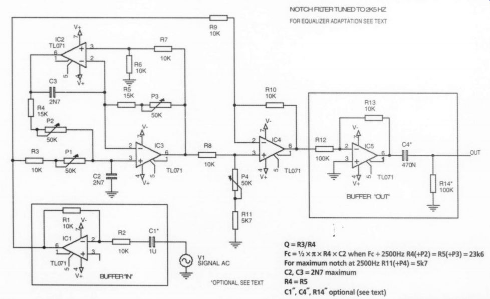
Q=R3/R4
Fc =0.5 x pi x R4 x C2 when Fc + 2500Hz R4(+P2) = R5(+P3) = 23k6
For maximum notch at 2500Hz
R11(+P4) = 5k7
C2, C3 =2N7 maximum
R4=R5
C1, C4, R14" optional (see text)
FIGURE 1: Notch filter schematic.
-------------------
The Filter
As in all of my equalization work, I elected the double amplifier bypass (DABP) as the working model. Together with a "summer" amplifier, it lends itself easily to either amplification or notching, i.e., cutting down on the volume as required.
It permits independent adjustment of all the three important factors: Q (i.e., bandwidth), frequency, and amplitude, using two twinned active op amps and one summer (Fig. 1). The parts list is in Table 1.
-----
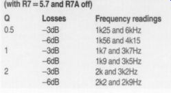
TABLE 1: CIRCUIT FREQUENCY READING (with R7 =5.7 and R7A off) Q 0.5 Frequency
readings 1k25 and 6kHz 1k56 and 4k15 1k7 and 3k7Hz 1k9 and 3k5Hz 2k and 3k2Hz
2k2 and 2k9Hz 1 2 b54R4]
----
I preferred two single amplifiers over a twin for quality considerations and ease of compensation if required. The DABP amplifier acts like a noninverting amplifier; i.e., it doubles the input voltage, which appears at the positive input of the summer amplifier. I assessed the response of the filter using a calibrated Radio Shack SPL meter with Stereophile number 2 CD as source of warble notes, placing the SPL meter in the usual listening location. I used it in "slow" mode with A weighting. You should use C weighting below 1k6Hz but from there up it under reads by 1dB at first, the error increasing to 3dB at 5kHz. Above 6kHz, the unit becomes un reliable even in A mode, under-reading grossly at any distance greater than 3' from the speaker.
Following are some practical considerations and component choices:
1. Linear trimpots P1, P2, P3, and P4 make all the critical parameters adjustable.
2. Re center frequency: Two 20k trim pots, P2 and P3, are adequate for fine adjustment around 2k5Hz if you use a 2n7F cap. For reliability, it is best to adjust both to the same resistance. If available, a high-quality (not the wiper type) ganged control is the most practical solution. The fixed resistor should be about half the calculated R4 = R5 value, i.e., +/-15k for versatility up or down the frequency scale. You may skip the P2 and P3 Filter center-frequency adjustment if you're satisfied with my choice of 2k5Hz, which appeared to be a satisfactory compromise in my room with my system.
To prevent oscillation, a minimum R3, R8, and R9 value of 10k is advisable at the op-amp inputs. Since the ability to achieve a minimum Q value of 0.5 is advisable, the C value should be 3nF or less. (See Fig. 1 equations. Q = R3/R4 = 0.42-for higher Qs, smaller capacitor values would be required.) An R3 resistor value of 10k would allow a Q of +0.5. The P1 trimpot could be 50k ohm, because I doubt that a Q higher than 3 would ever be needed in this context. Capacitor values higher than 5 may drop the R1 value below the minimum desirable 10k.
The summing amplifier is really a variant of the differential amplifier. A resistance between the positive input and the ground is necessary--without it, notching is impossible. Without resistance you will reach maximum amplification only at the price of op-amp instability. In addition, if you have no fixed-resistance R11 between the P4 trimpot and the ground, then, as you turn the trimpot for less resistance (counterclockwise if pin 3 and pin 2 are connected), you will reach the point where the voltage amplitude and phase will reverse, and you will start gaining voltage instead of losing it. By that time, you have spilled to the ground all the positive noninverted voltage, and at the output you are get ting only inverted voltage from the minus (-) input.
I used R11 = 5.7k as the minimum resistance necessary to prevent this "turnover." The voltmeter read a some what alarming --22dB voltage drop at f, but this lasted only for a few hertz, and even at the modest Q = 1 allowed for recovery to -3dB within half an octave-a minimum filter bandpass width. In practice, I preferred to leave the trimpot in the fully "off" position and rely on P1 for the required band width adjustment.
For the record, Table 1 provides the circuit's frequency readings for -3dB and -6dB losses when Q = 0.5, Q=1, and Q = 2, with R11 =5.7 and P4 off.
Needless to say, these readings are only a guide to real-life performance through the real life system in a variety of rooms.
(There should be unity gain at some position of the QO6A trimpot.)
Components
The resistors should be metal film; the capacitors polystyrene or polypropylene; the trimpots cermet, horizontal, single-turn for ease of adjustment. I find life too short for multiple-turn pots, and in view of wide tolerances in band width, I do not think ultimate accuracy is essential.
As op amps, I am using TL071s as my workhorses, not because I believe 1 could not do better, but because I experimented with two upgrades (Ne5534 and Burr-Brown OPA 604 and 2604) and found I could use them only at unity gain. They oscillated when used for amplifying or notching, whether the power bypass capacitor was tantalum or electrolytic. They might perform better with a satisfactory compensation network, but this would mean further component crowding.
To clue the filter in and out of the circuit, you will need a switch mounted in the box. This should be a miniature SPST (single-pole, single-throw). You will need DPST (double-pole, single-throw) if you insert the filter module between the two equalizer modules described later (Fig. 2).
You insert the unit between the pre-amp and the amp, or in the tape loop if you are using an integrated amplifier. At the exit, you will need a basic inverting amplifier as an exit buffer, and an identical input amplifier so as not to change the polarity of the whole. The 1mF cap at the input is needed only if you have no caps in the output of your preamp, e.g., when using an integrated preamp/amp unit. The same applies to the "exit" capacitor and resistor.
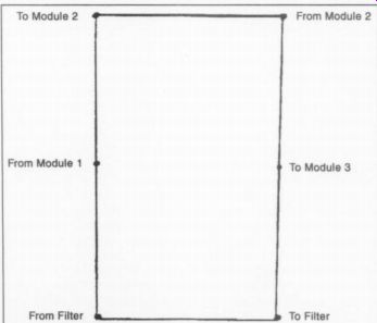
FIG. 2
As for power-supply regulation, use high-current, high-quality regulators LM317 and LM337. The R-adjust resistor allows you to adjust to the optimum voltage for the op amps you will be using
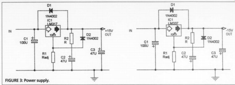
(Fig. 3).
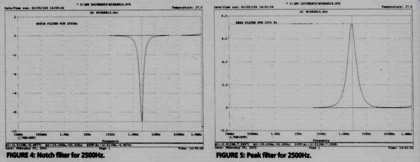
FIGURE 4: Notch filter for 2500Hz. FIGURE 5: Peak filter for 2500Hz.
Performance
The filter rehabilitates intolerable recordings, including some "great performances," to a pleasurable listening session. Naturally, the more correction that is needed, the more musical content will be lost until you arrive at a point of no return.
The filter is very convincing when an otherwise great recording requires only a moderate decibel correction over a narrow band. For example, the great Angel recording of Carmina Burana with Fruhbeck conducting, and several Glen Gould Bach recordings on Columbia are immeasurably more pleasant to listen to without soprano voices changing into a scream at higher volumes or the treble piano notes sounding like pistol shots.
(Regrettably, my filter could not get rid of Mr. Gould's chanting accompaniment.) All in all, I now have a larger us able record library. See computer simulations (Figs. 4-6). The printed circuit lay out is shown in Fig. 7.
Modular Parametric Equalizer
I will now explain how to adapt and expand the filter-unit design into a complete high-quality room equalizer (Fig. 8).
In AE 5/98 1 presented the design of an analog audio equalizer based on DABP bandpass design ("Tailored Filtering for Room Equalization" )--with a correction in the AE 2/99 issue. Here follows an update that I believe renders the project more flexible, more tractable, and above all incomparably easier to make.
The filter unit described earlier is essentially an equalizer module de signed to attenuate the 2k-3kHz frequencies. You can use, however, as many such units as you need for building blocks of a complete room equalizer universally adaptable to individual requirements.
In my original article, I described three designs I now they think can be discarded. First, there was an "augmented" DABP that would allow amplification greater than 9dB. Further very convincing experience, namely the flapping cones of three woofers blown up trying to get "enough" of a 20Hz tone, convinced me that buying a long-excursion subwoofer such as a Velodyne is ultimately a cheaper solution.
I concluded that if you need more than three times voltage amplification (i.e., +/- 9dB) to equalize your low frequencies, you should buy new speakers. The speaker tolerance is greater at mid frequencies, but there, forceful amplification must increase distortion, and be sides, it should hardly ever be necessary.
As for notching (rejecting), the DABP summer has almost unlimited capability.
I also proposed a "shelf" filter for wideband notching. Over the years I re placed it with one or two DABP modules. I found the shelf filter hard to control. It flattened out too much of the spectrum without controlling any of it adequately.
As for the biquad, it needs more amplifiers and more components than the DABP. Its theoretical advantage is the high Qs (i.e., narrow bandwidths) it permits. This is largely immaterial in equalization. Most corrections need moderately wide bandwidths. In fact, a very steep bandwidth may be accompanied by greater harmonics deformation and more abrupt phase reversal. In addition, experience showed that the summer unit in this application did not have an adequate range, and manipulation of the R3/R4 ratio was often necessary, with undesirable effects on the bandwidth.
The design has four trimpots per module. This crowding is regrettable, but experience has shown that with changing components and room treatments, you'll regret omitting trimpots more often than you'll find too many of them forcom fort-and rewiring is a pain. Note that your workbench figures are only approximations of what will happen in the room as the signal passes through your system.
Component Adjustments
As you descend along the frequency scale, progressively larger capacitor values are desirable. I used 27nF from 1kHz down, and 38nF at the lowest bass to keep the R1 values as low as possible to avoid reaching into the stratosphere at higher Q values.
For example, to allow a variation from Q=0.5t0
Q=5 at 20Hz, you will need R3 = 110k, with P1 = 1Meg.
Circuit Changes Required by Multiple Modules

Fig. 7
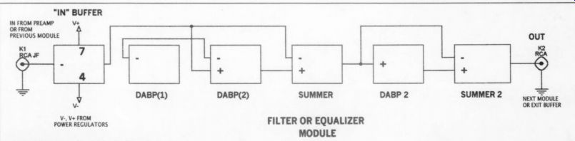
Fig. 8
Power-Supply Regulation: You could use one Sulzer-type regulator or Didden/Jung board for several modules. The up dated version with LM317 and 337 pre regulators is advisable. This should cover several modules, dispensing with separate regulation for each one.
Buffering: The "in" buffer is needed only with the first module, and can be jumpered in the following modules. The "exit" buffer is needed only with the last module, with the optional "exit" capacitor and 100k resistor to follow.
Equalization: The R7A trimpots need to be 2 for near maximum possible voltage (+/- 9dB). If you intend to use the module exclusively for either notching or amplification, the R7 fixed resistor can be 5.7k. But if you change components and wish adaptability, the compromise requires R7 = 10.5k with a 200k R7A trimpot. If you turn off the pot, you will lose -8.5dB at f.. If you turn it on fully, you will reach +8.8dB. Any larger trimpot value would gain you another 0.7dB to a possible maximum of 9.5dB. You should have unity gain at one trim pot's point.
Equalizer Performance
All in all, the DABP proved itself a serviceable model. By now I have about 12 "building blocks" per side. No doubt they have undesirable effects of their own, but the "equalized" Acoustat X and Quad ELS electrostats still sound immeasurably better when compared with the factory version. The same goes for my custom woofers. The distortion due to extra electronics is minute when compared to that due to the room/speaker interface.
When the modules are in a "flat" position and the equalizer is inserted between the preamp and amp, I am not aware of any difference when comparing it with the speaker connected "straight through." Any of the commercial equalizers I ever tested had a noticeable and un desirable "presence" in the "bypass" mode. I am well aware that the future of equalization potentially lies with digital technology, but at the price of what is available now, paying your mortgage comes first.
Reference:
1995, McGraw Hill, Electronic Filter Design; Williams/Taylor
Also see: