Here's a useful project to help the hearing-impaired enjoy TV by controlling the sound volume, separate from the TV speakers.
This is not a high-fidelity audio project, although for me it is a very necessary one. My dad has a 90% hearing loss, and his listening to the TV without blasting everyone else in the room is difficult. He tried headphones (in the TV jack) and the wire less modules that transmit audio to a dedicated battery-powered amplifier, but both solutions depend on the TV's volume setting. Any conversation in the room just adds to the distractions.
I decided to build an amplifier that can hook up to the audio output jack of a VCR, which is in turn used as the tuner for the TV. I added some tone-shaping controls and a volume control, so his audio level is totally independent of that of the TV. Portable audio provide unregulated +/-12V DC power supply rails for op amp. In addition, I locally bypassed the supply rails to U1 with 100nF ceramic caps. The only chassis ground connection for the circuitry is at the audio-input jacks, J2 and J3, which precludes any ground loops in the signal path.
LED 1 provides the power-on indication when S1 is on, and fuse F1 protects the power adapter. Power to the LED is half-wave rectified via CR1 and R1. CR2 and R2 then equalize the positive and negative supply currents, balancing the flux in the AC power-adapter trans former. I did this so the LED current would not increase the ripple on the filtered DC supplies.
Figure 2 shows the schematic for the input-summing amplifier and the two sets of tone controls I finally settled on after some experimentation.! VCRs are available with either mono or stereo ("Walkman") headphones complete the package. I put it together mostly with parts I had on hand, using a Radio Shack 270-274 enclosure.
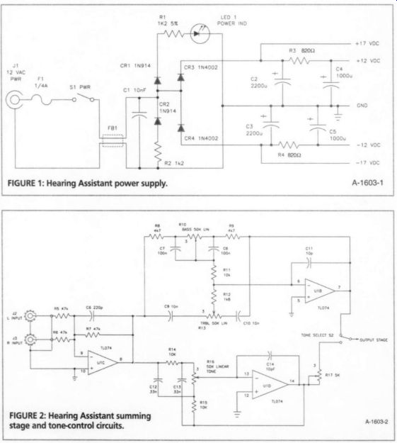
FIGURE 1: Hearing Assistant power supply.
How It Works
The schematic diagram for the Hearing Assistant power supply is shown in Fig. 1.
Power for the unit is obtained from a 12V AC, 0.5A plug-in power adapter. Thus there is no high voltage present inside the unit. The 12V AC supply at J1 is dual half wave rectified to + / - 17V DC.
Ferrite bead FB1 and C1 filter the rectification noise from CR3 and CR4.
Capacitors C2 and C3 filter the rectified DC, and resistors R3 and R4, in conjunction with C4 and C5, C6 220p R17 5x
FIGURE 2: Hearing Assistant summing stage and tone-control circuits.
…audio outputs, so I provided J2 and J3 to accept a stereo input. If the VCR you are using has only a mono output, just connect it to J2, or use a Y-splitter to connect it to both input jacks.
U1C is an inverting amplifier that also provides buffering for the two tone-control sections. C6 rolls off the high-frequency response to provide stability. I used a TLO74A quad op amp since maximum fidelity was not an issue. S2 allows you to switch between either of two active tone-control networks. I found that graphic equalizers were harder to use than simple tone controls, and the inter action between the bands caused some confusion.
Tone-Control Networks
The network built around U1B is a standard bass/treble control circuit. I adjusted the values so the center frequency was around 400Hz rather than the 1kHz used in audio equipment (Fig. 3). I found an application note that defined the normal speech range as 300Hz to 3kHz, but I also desired more treble boost with in this range.
The second tone-control network, built around U1D, is a kind of bandpass ...
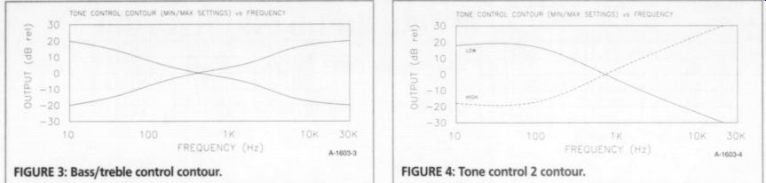
FIGURE 3: Bass/treble control contour.
FIGURE 4: Tone control 2 contour.
... filter that boosts one end of the spectrum while cutting the other. The con tour for this single control is shown in Fig. 4. It is effective for quickly isolating a smaller band of frequencies to improve intelligibility. Since it provides a bit more LOGY gain than the bass/treble section, R17 equalizes the levels so there is no volume change when switching between the two tone-control circuits. Note that for all the pots, the "3" designation is the CW end of the control.
Figure 5 shows the output-amplifier circuit that drives a standard set of portable audio-equipment headphones. I connected the stereo-headphone drivers in series by connecting output jack J4 as shown in the schematic. You need to insulate the jack sleeve from the chassis, or you will short the amplifier.
It is easy to drive this type of head phone to adequate volume levels with just an op amp such as the 5532. However, for the hearing impaired, much more volume is needed. I added a complementary-symmetrical common-emitter transistor output stage to U1A. The design is Class B, since high fidelity is not an issue, and it is more efficient.
There is no sense wasting watts with a flat response from 20Hz-20kHz, so I limited the 3dB bandwidth. R20 and C18 roll off the high frequencies above 15kHz, and R19 and C17 limit the low frequency response below 16Hz. You can adjust your design as you desire. If you need more gain, reduce the value of R19, while increasing C17 to maintain the same low-frequency 3dB point:
C= 1/ [2 pi R f_L]
Just make sure you do not drive the amplifier into clipping.
Stereo Version
If you wish to preserve stereo sound, you will need to make two sets of circuits, requiring ganged pots for the volume and tone controls. The input-summing amplifier will have only one jack per channel, so move R6 and J3 to the right-channel op amp. The input op amps are still needed to buffer the tone control circuits. Since the current draw will be higher, filter capacitors C2-C5 will need to be larger.
Construction
I used a Radio Shack 270-274 enclosure with dymo labels, since I wished to finish the project quickly and get it into | service. The circuit was wire-wrapped on a standard 4" pre-punched Vector board.
I mounted the board with 4- 40 nylon spacers, screws, and flat washers. I used 3"-long spacers because of the height of the wire-wrap pins. I have not shown the parts placement, since it evolved as part of my tone-control experimentation and is not really optimal. I also used axial lead aluminum caps, which take up more board space than the vertical-mount caps noted in the parts list (Table 1).
The pots, output jack, switches, and LED indicator are on the front panel. I used a large knob for the volume control, and smaller knobs for the tone controls. The headphone jack is directly under the volume control, and the input jacks, power jack, and fuse holder are on the rear panel. After in stalling the mechanical parts in the chassis, place the board near its final location and then wire to the switches, pots, and jacks. Use shielded wire from J2 and J3 to the board, from S2 to R18, and from R18 back to the board.
Connections
I connected the Hearing Assistant to the VCR with a 24' long Radio Shack 15 1540 A/V cable. You need to locate the unit near an AC outlet. The project worked out very well. The unit has plenty of clean gain, the tone controls give lots of flexibility, and the headphones provide isolation from the room acoustics and other distractions.
--------------
Hearing Assistant
Sources:
Mouser Electronics 958 N. Main Mansfield, TX 76063-4827 1-800-346-6873 mouser.com
Radio Shack Local stores, or Radio Shack Unlimited (RSU) 1-800-THE-SHACK tandy.com
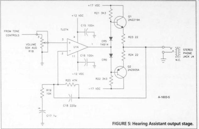
FIGURE 5: Hearing Assistant output stage.
Additional parts and materials:
Radio Shack 270-274 enclosure, Mouser 12V AC 500mA 412-212053 AC adapter, fuse holder, perfboard, pins, 14-pin DIP socket, control knobs, nylon spacers, LED mounting ring, hookup wire, shielded audio cable, solder, hardware, etc.
-----------------
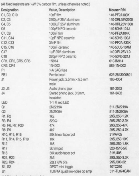
TABLE 1:
PARTS LIST (All fixed resistors are %W 5% carbon film, unless otherwise noted.)
Designation Value, Description C1,C9, C10 10nF film C2,C3 2200uF 35V aluminum C4,C5 1000pF 25V aluminum C6 100pF NPO ceramic C7,C8 100nF film C11,C14 10pF NPO ceramic C12,C13 33nF film C15,C16 100nF ceramic C17 1uF 25V aluminum C18 220pF NPO ceramic CR1, CR2, CR5, CR6 1N914 CR3,CR4 1N4002 F1 YA 3AG fuse FB1 Ferrite bead J1 Power jack, 2.5mm x 5.5mm male J2,J3 Audio phono jack J4 Stereo phono jack, 3.5mm, insulated LED T-1% red LED Q1 2N2219A Q2 2N2905A R1,R2 1k2 R3, R4 82 0-ohm RS, R6, R7, R20 47k R8, R9 47 R10, R13, R16 50k linear taper pot R11, R14, R15, R19 10k R12 1k8 R17 5k trimpot R18 50k audio taper pot R21, R22 3k3 R23, R24 22 -ohm %.W 5%
$1, 82 DPDT mini toggle U1 TLO74A quad low-noise op amp
Mouser PN 140-PF2A103K 140-XRL35V2200 140-XRL25V1000 140-50N5-101J 140-PF2A104K 140-50N5-100J 140-PF2A-333K 140-50U5-104M 140-XRL25V1.0 140-50N5-221J 610-IN914 583-1N4002 623-2643000801 163-4304 161-2052 161-3402 511-2N2219A 511-2N2905A 298J250-1.2K 29SJ250-2.2K 295J250-47K 298J250-4.7K 31VA405 295J250-10K 295J250-1.8K 320-1510-5K 31VJ405 295J250-3.3K 298J500-22 10TC260 511-TLO74CAN
Also see: