Marchand Electronics Mode PRAY Passive Preamp
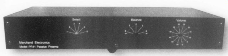
PHOTO 1: Marchand PR41 passive preamp.
The audio enthusiast searching for a separate preamplifier faces many choices. An active preamplifier offers low output impedance, and possibly a phono stage, tape-monitor loop, head phone amp, and tone controls. One proponent of the active preamp may prefer tubes, while the solid-state fan has a choice of op amps or discrete FET or bipolar circuitry.
A passive preamp, which is really a volume-control unit since it offers no gain, has the potential for absolutely transparent sound. However, the audio sources (CD player, tuner, phono pre amp, and so on) must be able to drive the passive attenuator, the interconnects, and the power amplifier.
Here you have more choices. The simplest passive preamp is a high-quality audio potentiometer. The rotary-switch stepped attenuator offers better attenuation accuracy, superior tracking between stereo channels, and longer life. All audio attenuators use make-before-break contacts to minimize switching noise.
The number of steps can range from a mere 12 on up to 60. The resistor net works can be arranged in series stepped, ladder, bridged-T, or bridged-H (balanced) circuits! The ladder attenuator has the lowest noise, with only two resistors in the circuit path at any time, but it requires twice the number of switch contacts, and is more expensive.
A set of relays can also do the switching (facilitating remote-control operation), with the help of some active logic-control circuitry.
Attenuator impedances range from 10k up to 500k. The lower values work well with solid-state amplifiers, while tube amps prefer the higher resistances.
The PR41 The Marchand PR41 passive preamplifier is a series-stepped attenuator design, with 46 steps of 1.25dB per step. Turning down the volume control adds more resistors to the upper-series string, and subtracts more from the ground-side string, causing more attenuation.
A companion balance control is connected in series between the signal source and the volume-control stepped attenuator for each channel. In its zero (centered) position, no additional resistance is added. Rotating the balance to one side adds resistance in 12 steps of 0.6dB each to the opposite channel only.
An off position is located at each extreme rotation, opening the opposite channel.
The circuitry is a true dual-mono de sign, and does not even share a common ground connection between channels.
The left channel is referenced to the chassis through a 10 0-ohm resistor.
The 17"W x 2.8"H x 8.5"D chassis consists of four black-powder-coated sheet steel panels. The front and rear panels are marked in white silk-screen lettering (Photo 1), with stylish black aluminum knobs. Exposed hardware is finished in black oxide to match the chassis.
The front panel has a six-position stereo-input selector switch, as well as the balance control and volume controls, which are both marked in dB of attenuation, and are accurate to 0.2dB when ...
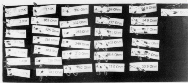
PHOTO 3
... used with a power amplifier that has a nominal input impedance of 50k. The rear panel has six pairs of unbalanced phono input jacks and a stereo pair of phono output jacks. A tape-loop is not provided. There is no power cord or power supply of any kind.
All the resistors in the balance and volume attenuators are 1%metal film. All the phono jacks are gold-plated with Teflon insulators. The source-selector switch is a Lorlin unit. The balance and volume controls are heavy-duty Shallco rotary switches with silver-alloy contacts on gold-plated connection posts. Each switch wiper uses two preloaded silver alloy contacts that ride on a silver-alloy stator slip ring. Even the lug connecting the chassis resistor to the left-channel ground is gold-plated.
Construction
All the parts you need for assembly are provided in plastic bags (Photo 2). The resistors are conveniently packaged in the order in which they are installed, and each resistor bag has the value and quantity written on a paper tag.
As is my usual practice, I took inventory of everything in the kit before beginning construction. Marchand provides an enumerated parts list, so you can easily detect any part shortages, and another list of the resistors by part number for use during assembly.
All the resistors were of the proper value. I always take the time to measure the value of each part. I'd rather identify a bad or incorrect part before I solder it in place and then need to troubleshoot later. The supply of color-coded hookup wire, which appears to be Tefzel-insulated, was much more generous than in many other kits I have built. Solder was not supplied with the kit, so I used Kester Electronic Silver Solder. The solderability of the pc boards, components, and wiring was excellent.
The assembly manual is complete, with clearly written instructions. The halftone photos are not very clear, but this does not hamper construction. In addition to the usual tools. you will need a 0.05" Allen wrench to disassemble the volume control, and a 0.063" Allen wrench for the control-knob set screws.
Three identical PC boards are sup plied for the resistor attenuator net works-two for the volume control and one for the balance control. Each board is double-sided, with plated-through holes and a solder mask. Assembling the boards is tedious, but straightforward. I pre-bent all the resistor leads and arranged them in order on a piece of antistatic foam I had on hand (Photo 3). I inserted the straight leads through the value tags supplied in each bag of parts, making it easy to locate the correct values as I needed them.
The instructions tell you not to bend over the resistor leads on the solder side, but I used a slight lead bend (Fig. 1) to hold each resistor in place while I soldered it. Make sure the solder flows through each plated through hole to the component side of the board, where the …
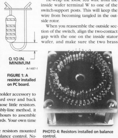
FIGURE 1: A resistor installed on PC board.
... jumper tracks are located.
…I used a Pana-Vise with the circuit-card-holder accessory to quickly flip the board over and back while installing all those little resistors.
Even with this assembly-line method, it took me about two hours to assemble each of the three boards. Your own time may vary.
Photo 4 shows the resistors mounted on the completed balance control. Notice the zero-W jumpers, which look like ordinary film resistors, but with only one black band.
Volume-Control Assembly Hints
While the instructions are certainly clear, I'll elaborate a bit on the disassembly and reassembly of the volume control. Before taking the switch apart, install a knob on the shaft and turn it fully counterclock wise. The movable contact is adjacent to a two-contact gap on the switch wafer.
When you disassemble the outside switch wafer, carefully remove the two brass washers in order between the switch contact wafer and the rotor. Keep the rotor and the movable wiper-contact set facing up at all times; otherwise, the contacts could fall out of the rotor.
After you install and solder the inner resistor-network circuit board, be sure to install the red wire to terminal W. You won't be able to reach it later when the volume control is reassembled. It was pure luck that I noticed a wire sticking out of the middle of the switch assembly in Picture 6 of the manual, which led me to investigate its purpose.
In fact, it is easier if you install the red and brown wires on the volume-control circuit-board W terminals, and those on the C and W terminals of the balance control circuit board before installing the switches in the chassis. The instructions tell you about installing these wires, but not until much later, in the chassis wiring section.
Tie-wrap the loose red wire from the inside wafer terminal W to one of the switch-support posts. This will keep the wire from becoming tangled in the out side rotor.
When you reassemble the outside section of the switch, align the two-contact gap with the one on the inside stator wafer, and make sure the two brass...
PHOTO 4: Resistors installed on balance control.
...washers are properly installed. Again, keep the rotor and the movable wiper contact set facing up.
Align the outside rotor movable con tact with the center of the last fixed switch contact after you reinstall the cotter pin. There is just enough free play in the rotor assembly to permit mis aligning the rotor and shorting across two fixed contacts. Tighten the set screws after the alignment is perfect, and then run the switch through all its positions a couple of times to recheck the contact alignment.
Be careful when handling the two switches after you install the resistor-net work PC boards. The complete volume control attenuator weighs over half a pound, and it could crush all those little resistors if you drop it, or even set it down, on the back end. The balance control is also fairly hefty, at 0.35 lb.
Chassis Final Assembly
Once the attenuators are complete, the chassis wiring goes fairly fast if you take my advice to connect the red wire to the inside volume-control PC-board terminal W while the switch is disassembled. I found it impossible to reach this terminal after the outside deck is attached. The wired chassis is shown in Photo 5.
When I installed the 100-ohm chassis-resistor lug under its star nut, I found that the 1/4" chassis screw engaged the nut only by one thread. I had a 6-32, 3/8"long black oxide screw in my hardware bin, so I used it to replace the screw supplied in the kit.
The only change I would suggest in the PR41 (other than the chassis ground screw length) is to add a shaft-extension kit to the source-selector switch. This would allow you to shorten all the wires between the input jacks and the switch.
Listening Tests
There is not much to listen to in a passive preamp. I normally use a solid-state preamp with a phono section, but I also have a passive preamp that I built with an Alps Black Beauty dual-conductive plastic potentiometer. I use it whenever I audition power amplifiers.
I used my regular interconnects-a 1m set between my CD player and the PR41, and another 1m set from the PR41 to my power amp, which has an input impedance of 60k. The PR41 was very quiet, as you would expect from a device with no active electronics or power supply. In theory, it is also quieter than my potentiometer, although the CD player and power amplifier were probably the limiting factors in hearing any difference. The wiper in the pot contacts the resistive element itself, while the wiper in the PR41 contacts a silver-alloy slip ring. The only noise sources are metal-film resistors, silver contacts, and solder.
The detent mechanism in the Shallco switch is spring-loaded, so the chassis makes a brief ringing sound when you change attenuator taps. (The volume control sings an A440, while the balance control, being closer to the center of the chassis, sings a halftone lower, at A'. The selector switch does not join the chorus, emitting only a slight click.) A number of passive preamps have 24 step attenuators with 2dB/step and a -44dB range. The 46-step volume control in the PR41, with its 1.25dB steps and -56dB range, is much more selective. My preferred listening level with
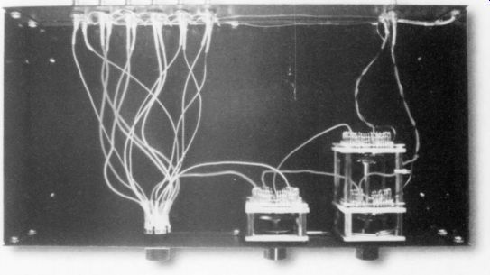
PHOTO 5: Wired PR41 chassis.
my power amplifier turned out to be at the "24" position on the PR41 (-24dB nominal). This means that my active pre amp is operating at much less than unity gain-as more of an active attenuator.
The balance control, with its 0.6dB steps, nicely complements the precise volume control; they work very well together. Despite the detent springs, the rotational torque is only a bit higher than that of the input selector switch.
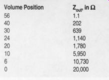
TABLE 1: OUTPUT IMPEDANCEWITH VOLUME POSITION
Measurements
I made all measurements after the listening tests, and there is little to measure.
No harmonic nor intermodulation distortion exists, and no clipping (unless you apply so much input voltage that you blow open a resistor). The noise is not measurable without special test equipment. I tried, but it was below the --107dB noise floor of my spectrum analyzer, without even the slightest bit of through-the-air 60Hz power-line pickup.
The input impedance was 20k for both channels with the balance control centered, and 34.2k with the balance control at the -6dB position (opposite channel measured). With the balance control in the off position, the opposite-channel input circuit was completely open.
The output impedance varies with the volume-control position, as shown in Table 1 (with the balance control centered). The position number corresponds to the dB attenuation with a 50k output impedance.
The frequency response for the PR41 proved to be ruler-flat from 10Hz 100kHz with my 1m-long test-setup interconnects and 600-ohm sine-wave oscillator. I ran this test with the volume control set for "24," which is the same position I used in the listening tests. Since passive preamps are reputed to be very sensitive to their interconnect cables, I made another set of frequency-response measurements with an LRC network (Fig. 2) having the same impedance as a 25' (7.5m) interconnect.
Figure 3 shows the frequency response for output loads of 100k, 47k, and 20k. Notice the highly compressed vertical dB scale. The response was essentially identical for both channels. With the simulated 25" interconnect (dashed lines) you can see a slight high-frequency rolloff. Also interesting is the little effect of the 5:1 output impedance change on the attenuation. At -24dB, the PR41 has an output impedance of only 1.14k.
I also made crosstalk measurement with the volume control at "24." Since crosstalk is a function of how well you separate the wiring between channels during assembly, your own results may vary. All the input-signal wiring converges at the input selector switch, so it is the most susceptible wiring location The high-frequency crosstalk was a bit higher from left to right, as Fig. 4 shows.
Conclusions
The Marchand Sound PR41 is extremely quiet, with great dynamics and no coloration. Its six line inputs provide nice versatility. The kit is rugged, well de signed, and foolproof to build. A balanced version is also available. If you find that your active preamp is used primarily as an attenuator, you may wish to consider the PR41.
----------------

TABLE 2: MANUFACTURER'S SPECIFICATIONS
Frequency response: DC to 100kriz + 0.5dB Input impedance: 20k, with balance control centered Volume control: 46 steps at 1.25dB/step, -56dB to 0dB Balance control: 12 steps at 0.6dB/step, -6dB to zero to -6dB.
Volume and balance accuracy: 2% (0.2dB) Output load: 50k typical Kit price $495 Available from Marchand Electronics Inc., PO Box 473, Webster, NY 14580, 716-872-0980, FAX 716-872 1980, info@marchandelec.com, http://www.marchandelec.com
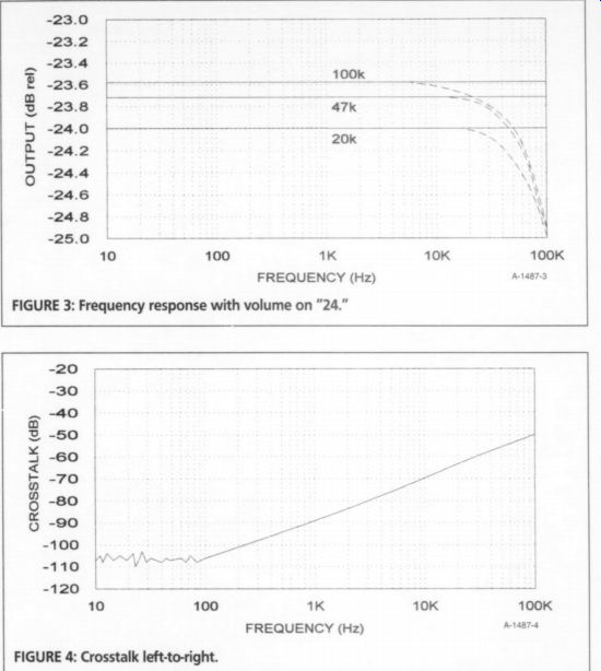
FIG. 3.
FIGURE 4: Crosstalk left-to-right.
--------------
Manufacturer's response:
Thanks to Mr. Hansen for his excellent review of our PR41 passive preamp kit. The remarks he made regarding the assembly are well taken and his review makes a good addition to our assembly manual. We will try to improve the manual with some of his suggestions.
A passive preamp is not for everyone, but if you desire clean sound and have enough gain from the power amps, then it is a good choice.
We offer the PR41 in three versions. The kit as described here is the PR41-KK, the full kit. It is also available fully assembled (PR41-AA) and as an EZ kit (PR41-EZK). The EZ-kit comes with the attenuators fully assembled, which makes assembly of the preamp a snap.
Phil Marchand, President, Marchand Electronics
1. There have been a number of articles on passive attenuators in Audio Amateur magazines over the years, some of which I have listed below.
D. Crawford, "A Well-Balanced Low-Noise Volume Control," Audio Electronics 3/98, p. 8; 4/98, p. 43; 1/99, p. 46.
J. O'Connell, "Stepped Attenuator for Balanced Audio Amps," The Audio Amateur 3/91, p. 34.
J. O'Connell, "Stepped Volume Controls," The Audio Amateur 3/89, p. 33.
J. O'Connell, "Computer Programs for Stepped Volume Controls," The Audio Amateur 4/88, p. 43.
L. Hupp, "A Ladder Attenuator," The Audio Amateur 5/82, p. 20; 1/83, p. 54.
Also see: HHB Compact Disc Recorder