An otherwise good design can come to naught through poor layout and construction. The final part of this article addresses this important facet.
I constructed the 100W amplifiers referenced from time to time in this article as monoblocks because it is difficult, using purely passive methods, to adequately cool a piece of equipment that dissipates 500W. Active cooling methods, such as ventilation fans, are undesirable due to their associated acoustical noise when operating. The A40M constructed as a stereo unit dissipates less power than a single 100W monoblock, so I built the prototype as a stereo pair.
To be more precise, I built the proto type A40M as a (largely) dual-monaural amplifier in which only the enclosure and the components from the AC power line to the transformer primary are common to both channels. You are certainly free to build the A40M as two monaural units, which would have the advantage of cooler operating temperatures and allow closer placement of the amplifiers to their associated speaker loads.
The 100W monoblocks, for example, sit immediately behind Martin-Logan ReQuest loudspeakers, joined to them by 2' of 8-gauge and 12-gauge cable in a biwired configuration. To avoid seeming hypocritical, 1 hasten to add that while I don't believe there is any significant benefit to bi-wiring, I did it because it was easy to do and made my golden-eared friends happier.
The disadvantages of monaural construction are the increase in metal work, component count, and expense of the additional components. This last factor is not inconsequential, since the power transformer is the single most expensive component. Although the smaller power transformers used in the monaural units would be individually cheaper, their combined cost would be appreciably more than the single larger transformer required by the stereo version. Given the aggravation of amateur metal-working, I think this, too, is not an inconsequential factor.
Enclosure
The two major considerations for enclosure (chassis) selection are that the internal volume must house all the components except, perhaps, the output transistors, while the external surface must accommodate the heatsinks required for the output transistors. It is possible to mount the output MOSFETs to a bracket which, in turn, you bolt or otherwise thermally join to the heatsinks so that these transistors are also within the enclosure.
I prefer to mount the transistors directly to the heatsinks, because this avoids yet another thermal junction with concomitantly higher thermal resistance between junction and ambient. However, you can often achieve more aesthetically pleasing results with the internal bracket approach. This is yet another example of a trade-off.
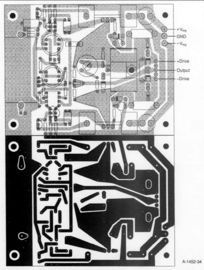
FIGURE 34: Amplifier front-end printed-circuit pattern and parts placement.
As to the volume requirements for the enclosure, my recommendation is to purchase the power transformer and then use its dimensions as a scale factor in determining the needed volume. The heatsinks you use will dictate the height and depth of the enclosure, since they are usually mounted on its sides.
In the case of the A40, the process was partially reversed in that I had purchased for $5 a surplus chassis that would house the original A40 power transformer. I then minimized the PCB sizes and selected the largest commercial heatsinks I could find that would fit on the chassis. At that, the four heatsinks on each side extended beyond the back of the chassis, so that I needed an "L"-bracket to extend its depth. The heatsink area should be no less than about 100in? per output MOSFET.
Wakefield no. 441 or Thermalloy no. 6441 are commercial heatsinks that would work in this application.
Layout
A first rule is that input and output should be separated as much as reason ably possible to avoid stray coupling that could lead to oscillation because of the unintended feedback path. I have not en countered this problem even where input and output terminals were only a couple of inches apart. Since other authors highlight this potential problem, I shall, also.
It is difficult to imagine that wire lengths can pose a problem at audio frequencies, but apparently they can, since some amplifiers that work fine when constructed in nearly cubical form with short leads tend to oscillate with more "open" construction and longer leads.
This occurs despite the fact that compact construction offers a greater chance of stray coupling than more open construction.
Inductance is intrinsic in wires and can lead to frequency-dependent effects and even oscillation. Unless current changes rapidly in a wire, the small inductance should not induce much of a voltage. From the discussion on slew rate, a combination of high frequency and amplitude could perhaps cause a problem.
Long power leads to the output transistors, then, at least potentially cause similar problems, although neither the 100W monoblocks nor the A40M seem susceptible to this, given that the power leads in those units could not be particularly short because of the physical layout. In general, larger-gauge power leads are better, but a reduction in wire length reduces inductance proportionally more than does an increase in wire diameter.
As an indication of how little inductance you need in some instances, there are audio power amplifiers that have a few turns of wire in series with the output connection. This small air-core inductor is all you need to isolate the amplifier output from reactive loads that would otherwise cause high-frequency oscillation by lagging the output and thereby the feedback error signal.
The A40M output shows some peaking but no oscillation when driving capacitive loads up to 2 uF with no inductor used. If you add an inductor for any reason, check the output waveform with an oscilloscope. It may be necessary to reduce circuit Q by paralleling the inductor with a 2 or 5W power resistor of 1 ohm or so to eliminate overshoot and ringing. The inductor can actually use the resistor as a coil-form to conserve volume.
As a general rule, try to keep power and signal-path leads as short as possible.
In the A40M, this includes the path between the front-end PCB and the output MOSFET gates. The construction of the A40M prototype worked fine.
[...]

FIGURE 35: Power-supply printed-circuit pattern and parts placement.
... them (Fig. 34). In fact, the heatsink for Q11 interconnects two ground traces on the board and is therefore an essential part of the electronic circuit.
You must electrically insulate Q11 and Q12 from their heatsinks with some type of insulator. Some insulators do not require silicone grease, but the commonly used mica insulators do, because otherwise their thermal resistance is unacceptably high. It would be best to use mounting hardware designed for heatsinking applications, since this hardware is available in individual kits that often include the insulator, a feed-through insulator for the mounting bolt, and a spring washer. In combination, the kit allows simultaneous electrical insulation and good thermal coupling between transistor and heatsink, along with easy and safe torquing of nut and bolt.
It is not a trivial matter to mount transistors to heatsinks. Improper mounting can produce poor thermal conductivity or an electrical short; it can even cause transistor damage, although that is unlikely unless the mounting bolt and nut are severely overtorqued. After mounting them, check continuity between the collectors of Q11, Q12 and their heatsinks with an ohmmeter. An open circuit (no continuity) should be present.
For Q11's heatsink, make sure that there is continuity between the PCB's main ground trace and the emitter of Q7.
If there is no continuity, it is probably easier to solder a wire between the two traces than to manipulate the heatsink connections to the board. If you do this, be sure the wire touches no other traces.
There is no need to insulate Q14 from its heatsink, since the mounting bolt electrically connects the transistor's mounting bracket to an underlying board trace to which the transistor's collector lead is already soldered. As you can confirm with the ohmmeter, Q14's metal mounting bracket is internally connected to its collector lead. However, you must still take care that the mounting nut on the trace side of the PCB does not touch the adjacent positive output trace.
The heatsinks for Q101, Q102 on the voltage doubler/regulator board are also solderable-pin types (Fig. 35). Mounting is similar to that already described. These heatsinks are "floating," i.e., unground ed.
Thus they require no insulator, but you do need to apply silicone grease between transistor and heatsink.
Output MOSFETs
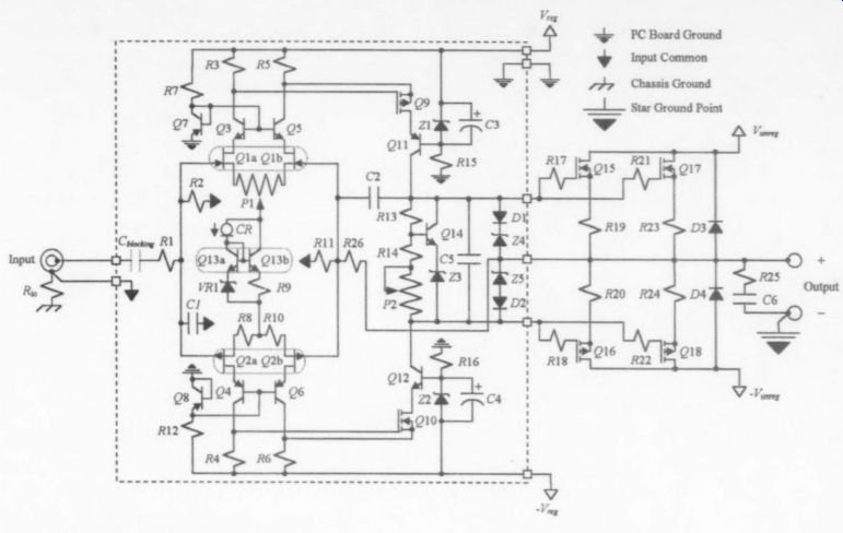
FIGURE 36: Amplifier schematic.

FIGURE 37
The output MOSFETs, while of a different physical construction than the other heatsink-mounted transistors already discussed, nonetheless require the same considerations. There are, again, heat sink mounting kits that provide the (two) appropriate mounting bolts, nuts, and washers, as well as the required insulators. Although they're not essential, you can use transistor sockets with the MOSFETs. If you do, make sure they are of good quality, because the source and gate contacts are prone to high resistance if they become loose.
You should connect the gate resistors directly to the gate lead or the gate terminal of the socket. Since gate currents will not be overly large, 20 AWG wire is a good choice for interconnection of the gate resistors and the positive and negative drive connections on the front-end PCB. Since the MOSFET cases are electrically connected to the drain internally, verify with an ohmmeter that no continuity exists between case and heatsink.
The heatsinks themselves should be electrically grounded to the chassis; this requirement usually takes care of itself via the bolts that attach the heatsinks to the side of the chassis. In the A40M prototype, I placed an additional small anodized heatsink over the case of each MOSFET. This looks good, affords some minor additional heatsinking capability, and offers protection against shock from touching the case of one of the externally mounted power devices. However, this protection can be compromised should a scratch or other damage breach the anodized layer.
Hardware
A glance at the amplifier schematic (Fig. 36) reveals the presence of connectors, fuse holders, a switch, and other chassis mounted hardware. It is usually a good idea to separate the power-supply components from the signal components. In the 100W monoblocks, the power supply was on one side, with the signal circuitry contained on the other. Power-supply components (Fig. 37) in the A40M are mostly in the front of the enclosure, and the signal circuitry at the rear. Obviously, the power connector and line filter must also be at the back, so the physical separation is not complete.
Mounting hardware may or may not be supplied with toroidal power transformers. The 100W monoblocks contained two small toroidal power transformers wired in series and mounted vertically to either side of a vertical metal bracket.
They did not come with mounting hard ware because they were purchased as surplus items for $15 each. I used stove bolts and home-brew insulating cushions to mount them to the bracket. Be careful to avoid shorting windings to the chassis when mounting toroidal transformers.
Again, rubber insulating cushions are usually supplied with manufacturer-sup plied mounting kits.
I recommend good-quality chassis mounting RCA jacks. Since jacks can corrode, gold-plated variants are best.
The jack must be completely insulated from the chassis; a 10 ohm resistor is subsequently connected between its ground lug and the chassis. Connection between the jack and the front-end PCB is best effected via shielded audio cable.
For output (speaker) connectors, I prefer heavy-duty, gold-plated, five-way binding posts. These can be dual or single, but if they're single, use one red (+) and one black (-) binding post for each channel, mounted with the same spacing between them that exists in a dual unit. This allows the speaker-cable terminations at the amplifier end to be the very convenient dual banana plugs.
The high current levels at the output of a power amplifier dictate low-resistance interconnections, and there are connectors superior in this regard to those used in the A40M prototype. It is doubtful that the very slight improvement merits the considerable difference in cost, but this is my engineering judgment. Vertical or horizontal (or any other) orientation of the binding posts is acceptable. You must insulate all output connectors from the chassis. I recommend heavy-gauge wires of 16 AWG or thicker for the interconnection of these connectors with the output and the star-ground point.
Lurking Load
The output-filter components R25 and C6 are mounted between the internal solder lugs of the five-way binding posts.
Since the A40M displays no instabilities on the test bench with various loads, this is obviously an acceptable location for these components. Other locations would probably also be acceptable, since I added this filter in obeisance to those masters who have preceded me, rather than on the basis of a demonstrated requirement. In bench tests without the filter, I detected no differences. Nelson tells me that a load lurks out there some where that will need the filter.
Although not essential, a three-terminal chassis-mounted AC power receptacle is convenient and provides a more professional appearance. The fuse holders are standard chassis-mounting units.
You should use insulated wire of 18 AWG or heavier to connect the power line fuse to the receptacle and the on-off switch. The DC-rail fuses should be connected to their respective circuit points with wire that's 16 AWG or heavier.
I placed the relay, thermistors, and Reps Repo on a small PCB that was in turn mounted to the positive terminal of the filter capacitor C and the negative terminal of C_unreg- NO pattern is provided for this board because its dimensions and layout will depend upon the particular physical construction of a given A40M. You can use chassis-mounted relays that would entirely obviate the need for this special PCB. This is a builder option.
Use 16 AWG or heavier wire to connect these components to the bridge rectifier. Obviously, the board traces to which the thermistors and relay contacts are connected will need to be equivalently broad. For example, 0.1" wide traces are acceptable for currents up to 5A, 0.2" would be okay for up to 10A, and so on.
Wire Interconnections
Connections to the drain and source of each output MOSFET should be via 18 AWG wire or heavier. If the output-MOS FET source-degeneration resistors are connected directly to the transistors' source terminals, you should use individual 18 AWG interconnections between the other end of the resistor and the positive output binding post. Actually, completely separate interconnections are not required, but if, for example, the Q15 drain is connected only to the Q17 drain, and the Q17 drain is then connected to the V_unreg fuse holder, 18 AWG is fine for the former connection, while a heavier gauge is indicated for the latter.
If four collectors were tied together, as might be the case in a common-supply stereo version, then you should use at least 16 AWG interconnections. These values are conservative when compared to data taken from electrical code requirements that dictate allowable current levels for various wire gauges.
Tables containing this information are in the ARRL Handbook, the CRC Hand book, and other sources.
All my power-amplifier designs contain a speaker fuse. Some will argue against such fuses on the basis of an adverse sonic effect that is probably undetectable in blind testing. Fuses have resistance, which is larger in those with smaller values. Increased output resistance will increase damping factor, an undesirable consequence. On the other hand, destruction of an expensive driver in a loudspeaker is also an undesirable potential consequence of failure to provide a speaker fuse.
All audio power amplifiers have failure modes that can take the output to the rail, and my inclination is to protect against that eventuality. Since output current can peak at 3.2A in normal operation, a 3A fast-blow fuse will protect an 8 ohm speaker while holding up at all but the most severe output levels.
Bear in mind that the speaker-impedance specification is a nominal AC value that usually varies markedly over the audio range.
DC Resistance
In my somewhat limited experience, the measured DC resistance (by definition, resistance is the applicable quantity at DC) of a speaker is close to the specified nominal impedance, but this is not necessarily so. Measure the DC resistance, note the manufacturer's nominal impedance specification, and then select a fuse rating that offers good protection should +30V DC suddenly appear across the speaker terminals. The lower the rating of the fuse, the better the protection, but it is unfortunately also more likely that the fuse will blow in ordinary listening.
Here, as you have now seen a number of times in this design, another compromise is required. It may be that no good compromise fuse rating exists for a given speaker. In that case, you must either use some other method of protection, or run the amplifier with no protection. At least your golden-eared friends will be happier if no fuse is used. (But if you don't tell them, they will never know.) I recommend using quick-disconnects (QDs) for PCB connections-gold-plated ones for reliability. There are a number of different types; for example, Molex connectors. The spacing for the external interconnection points on the provided PCB patterns are based on the use of particular QDs. You may need to modify these spacings if you use other types.
While the serious golden-ear will eschew the use of QDs in favor of directly soldering interconnecting wires to the PCB, it is very frustrating to perform maintenance on boards that have hard wired interconnections to other circuit elements. The first time you perform such maintenance, you'll find that the QDs are worth their weight in gold. If you are of the golden-eared ilk, you'll prefer to use silver or some other exotic solder, I am sure, for its sonic purity.
The PCBs must be insulated from the chassis or other circuit elements. In the prototype, I accomplished this with standoffs, which are widely available in various heights. The height should allow clearance between the chassis and any part of the trace side of the PCB. The board patterns in Figs. 34 and 35 are such that the standoffs themselves may not need insulating. If you use metal standoffs, however, be certain they do not touch any PCB traces. As alternatives, use Teflon® or other insulating standoffs.
Adjustment
Due to the DC capability of the amplifier, you must make an initial adjustment of the DC offset at the output. Because of the precise Class-A bias level desired, a second initial adjustment is required to set that bias level. Both adjustments are simple and probably will never require readjustment (the A40M prototype has never required a readjustment in seven years of operation). Take care in initial setup and checkout so that blown fuses or damaged parts do not result. I recommend a Variac for the initialization exercise.
To facilitate checkout of the front-end boards in the prototype, I added resistors to provide feedback. The front-end PCB patterns accommodate these resistors.
You should therefore ignore the two resistors shown in Fig. 34 above and below resistor R26.
Initialization
Before power on: Make sure that the wiper of trimpot P1 is at its midpoint, since reasonable matching of input-stage devices should cause the output DC-null point to occur at or near the wiper mid point. Since output-stage bias levels increase as the resistance across trimpot P2 decreases, you should set the P2 wiper to yield the highest resistance.
Unfortunately, trimpots are produced with either clockwise or counterclock wise sense; that is, resistance will be maximized in either rotation extreme, depending upon the manufacture. Use an ohmmeter to guarantee that resistance is at its maximum.
You can operate solid-state amplifiers safely without a load. No load should be attached during initial setup. Place fuses for power line and rails as described in the text. Use the minimum recommended values initially.
If two voltmeters are available, use one to measure output-stage bias level and the second to measure output offset voltage. Placing the leads across any of the source-degeneration resistors R19, R20, R23, or R24 effects the former measurement. The latter is made by attaching the positive lead to the positive output terminal, and the negative lead to the negative terminal. If you have only one voltmeter, use it for the bias-level determination, and use an oscilloscope, if available, in DC input mode to monitor output offset. All devices used should be set at their lowest DC voltage range.
Power on: If you use a Variac, set it at zero before power on. Plug the A40M into a 117V AC power outlet and switch the A40M power switch to the "on" position. If DC voltage is no more than a few millivolts across the source resistor, then check DC output voltage, which should be less than 1V. If voltage across the resistor is more than 50mV (or zero, which may indicate a blown rail fuse), or output voltage is more than 1V, then immediately power off the amplifier and look for obvious problems.
Causes of excessive bias voltage are a misadjusted P2 trimpot or some circuit error or failure. The most common causes of excessive output-voltage offset are a misadjusted P1 trimpot or mismatched input JFETs. Of course, circuit errors or failures can also cause high offset voltage.
Bias: This is usually the more critical initial adjustment, assuming that no load is attached to the amplifier. Since the source resistors have a value of 0.1Q, the current through them-and hence through their associated MOSFET-is equal to ten times the measured voltage across them. Since each output MOSFET should have 0.8A drain current, slowly adjust P2 until the measured voltage is 80mV. Rapid adjustment may result in overshoot, which, if severe, should only blow a rail fuse, but why take chances?
DC offset: Once bias level is set, direct your attention toward nulling the DC offset at the output. It is imperative that no load be attached until this step is complete. Adjust P1 slightly. Output voltage should increase or decrease slightly with the adjustment. Continue to adjust P1 until voltage is zero or only a few millivolts at most. It is normal for this voltage to fluctuate a few millivolts. If you can change the voltage by adjusting P1, but nulling to zero is impossible, JFET mismatching is the likely cause.
Readjustment: Let the amplifier operate for at least 30 minutes, and then readjust both bias and output offset. Bias may have fallen slightly for reasons discussed in the text. If so, and the fall is only a few millivolts, then readjust to 80mV. Output offset may now be as much as 50 or 60mV, and anything up to about 0.1V is acceptable. Higher than this is excessive and may indicate unusual device sensitivity to heat, unequal thermal conditions in different parts of the circuit, or a transistor that is not firmly affixed to a heatsink.
Operation
Assuming that these procedures are successfully completed, you may now attach a load to the amplifier. If a dummy load, signal generator, and oscilloscope are available, it is a good idea to put the A40M through its paces while monitoring performance on the test bench. However, if the initialization went as described, a serious problem is unlikely.
Power off the amplifier, place a 1A fast-blow speaker fuse, and attach a signal source to the input and a loudspeaker to the output. Upon power up, you will hear a mild thump in the speaker. With source material playing, gradually turn up the preamplifier volume. The reproduced material should give no evidence of distortion. If distortion is present, power down and recheck the amplifier and all the connections. Otherwise, the amplifier is ready to use.
Judgment
A famous designer, Nelson Pass, once told me there is no music sweeter than that which you (re)produce yourself.
Although the amplifier is near the end of the reproduction chain, there is a certain extra thrill of listening to music via an amplifier you have built yourself. The final proof of the pudding will be in your subjective evaluation.
I still am impressed with the sound when passed through the A40M. Equally impressive has been the seven-year trouble-free operation, no mean feat for an amplifier legitimately rated at 40W/channel Class A. I hope that you enjoy the amplifier if you construct it, and that, in any event, you found this series useful.
Also see: