Voltage level is a critical area of audio work. Construct this power line monitor to ensure long-term accuracy.
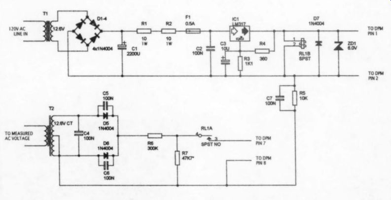
FIGURE 1: DPM power supply and measured voltage.
An AC powerline monitor is a use
A piece of test equipment for many people in audio design and construction work. I frequently use a Variac to initially apply AC power to a new project, and to verify DC-regulator operation over the possible wide AC-line variations I experience.
My typical method of measuring the AC line was to use one of my DMMs (dig ital multimeters). The problem with this is that the probes don't fit well (or at all) into standard duplex outlets. So I was al ways jerry-rigging a clip-lead arrangement, which is not the safest way to proceed--or I would forget to turn off the DMM and kill the 9V battery. I needed a meter dedicated to this purpose that I could safely plug in and forget, so I decided to attempt this project.
(see parts list). The DPM operates on a 5.0V supply and has a 2.0V maximum input. I chose a LED display instead of LCD because it's easier to read and, to me, just plain better looking.
The design is essentially two low-voltage power supplies (Fig 1). One is dedicated to providing regulated 5.0V to power the DPM, and the other conditions the AC line voltage to meet the DPM input-voltage requirements. Both sup plies are fully isolated from the AC line with transformers, as well as being isolated from each other. Under these conditions, C-TON recommends connecting together the common of each supply through a 10k-ohm, 100nF parallel RC arrangement to avoid ground-loop problems. R7 and C7 meet this requirement.
The "measured voltage" conditioning supply uses a full-wave rectifier, the average values of which are directly related to RMS values for sine-wave signals, and the circuit provides for calibration to RMS values using the procedure de scribed in the Operation and Calibration section that will follow.
DPM Power Supply
This is a straightforward supply that uses an LM317 adjustable regulator designed for 6.0V output. The DPM is the most expensive part in this project, so I decided to include some protection features. C TON states that 6.0V is the absolute maximum supply voltage. To protect the DPM from a possible LM-317 input-to output short condition, I placed a 6V zener diode across the power-supply terminals.
If the 317 shorts, the zener will clamp the supply voltage to 6V and draw enough current to blow F1. Series resistors R3 and R4 reduce the 6V regulator output to the 5V required by the DPM.
Under the potential fault condition de scribed, they also limit zener current and provide the additional benefit of reducing LM-317 power dissipation.
Actually, standard zener voltages are either 5.1 or 6.2V. You have two choices-test 6.2V zeners until you find one that measures 6.0V or less (the method 1 used); or use a 5.1V zener in series with a 1N4007 silicon diode. Either method [...]
PARTS LIST
Digital Panel Meter (DPM)
3 1/2 digit, red LED DPM, 2.0V DC input, 5.0V supply-C-TON: Digi-Key PINCDPM605-ND Resistors-all are Yageo 1%, %W metal film, except where noted.
R1, R2 10 ohm 1W; Radio Shack PN 271-151; or one Yageo 2W 200) Digi-Key P/N 10W-2-ND osci +5VDC
WIRING RS 10k-ohm R6 300k
od A R7
Approximately 47. 7k-ohm-selected value; see text
Capacitors
C1 2,200 pF 25WV
DC electrolytic; Hosfelt P/N 15-518 C2,C4-C7 100nF, 100V mono; Hosfelt P/N 15-905 or 15-859 C3 10pF, 16WV DC tantalum, Hosfelt P/N 15-901 Diodes ovesng ppt S D1-D7 1 Amp 100V PIV 1N4002, Hosfelt P/N 1N4002 faa ZD1 6.2V zener diode selected for 6.0V; Hosfelt P/N 1N4735A, or Hosfelt P/N 1N4733A in series with Hosfelt PAN 1N4002
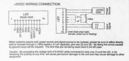
FIGURE 2: C-TON D Transformers T 12.6V CT; Radio Shack P/N 273-1365 (or similar) T2 12.6V CT; Radio Shack P/N 273-1385 (or similar) RL1 SPST 5V DC coil, Radio Shack P/N 275-240 (or similar) Fuse Fi 500mA fast-blow
r- Aluminum enclosure Digi-Key P/NHM322-ND
AC Line-Voltage-Conditioning Supply
I chose a 12.6V center-tapped transformer to reduce the measured voltage to a range suitable for the DPM (2.0V maximum). I initially used a capacitor-input filter, trying values from 1,000uF electrolytic to 470nF metal film and polypropylene. Using this type of filter, I was unable to get long-term accuracy of better than 2% compared to a reference AC DMM.
---------
FIGURE 2: C-TON DPM wiring.
--------------------
The final solution was to eliminate the capacitor-input filter entirely. The average DC value is calibrated to RMS value with R5 and R6. With this circuit, the long-term accuracy has been better than 1.0%. As of this writing, my power-line monitor has been operating continuously for over 500 hours with no failures; it maintains 1.0% maximum accuracy, and is typically better than 0.5%.
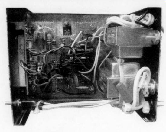
PHOTO 1: Top view of completed project.
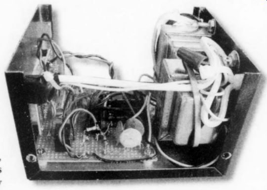
PHOTO 2: Side view of completed project.
Resistors R5 and R6 form a voltage divider for calibration from average to RMS value. I installed relay RL1 to pre vent application of measured voltage to the DPM input if the DPM is powered down, and the measured-voltage section is still connected to the AC line. At power-up, RL1's normally open contacts close, applying measured voltage to the DPM only when regulated voltage is available from the DPM power supply.
Construction Details
Follow the wiring diagram C-TON provides with their DPM (Fig. 2):
«pin 1 =+5.0V power supply;
+pin 2 = power-supply common;
«pin 7 = input signal +;
+ pin 8 = input signal-;
«jumper pin 3 to pin 4 activates least significant-digit decimal point.
Photos 1-3 show the parts placement. This project was a good example of Parkinson's Law: "The components will expand to fill the available space." I thought I had plenty of room when I started, but initially I didn't plan for the added protection circuitry. It still worked with point to-point wiring and perf board construction.
The specified enclosure comes with a coat of gray primer applied. You may prefer to paint it with your favorite color after completing your sheet metal work. Make sure you drill ventilation holes in the enclosure bottom and sides as shown in Photo 4. Total active-device power dissipation within the enclosure is about 3.2W, and this does not include heat generated by the transformers. Ventilating the enclosure will allow continuous operation and reduce the temperature drift of calibration resistors R5 and RG.
C-TON provides a diagram with all dimensions for DPM mounting, but it's not printed at actual size on their rather sparse data sheet. The enclosure cutout required for the DPM plastic bezel turned out to be the hardest part of the construction, so I redrew C TON's diagram and made it actual size so you can photo copy it, cut it out, and use it as a template (Fig. 3). I wish I'd thought of this before I started.
C-TON also states that a pair of 2-56 screws is included to mount the DPM to the bezel. Self-tapping screws were supplied with mine, and the DPM PCB holes were drilled too small for clearance. I re-drilled them with a Dremel tool to provide clearance for 2-56 machine screws, which I had on hand (available from Radio Shack).
The bezel mounting holes are not threaded. I strongly recommend that you mount the DPM to the bezel before mounting the bezel to the chassis.
Doing so gives you more leverage for using the screws to thread the bezel, and you can take extra care in the process. After threading the holes, disassemble the bezel and DPM, and mount the bezel to the chassis using the 2-56 screws and two supplied mounting clips.
Mounting the Transformers
Mount the transformers and wire the power switch. It's very important to use tape or heat-shrink tubing to insulate the switch contacts. It would be easy to bump the switch contacts with power applied, so they pose a shock hazard unless they're well insulated. I used standard zip cord with two-prong plugs for both AC inputs. Use rubber grommets, or suitable insulated strain-relief hard ware where these power cords pass through the rear chassis. Wire the mounted transformers to their respective rectifiers on the board before mounting the board to the chassis.
The final value of R6 will need adjustment, the procedure for which is de scribed later in the Operation and Calibration section. Temporarily install a 47k-ohm) resistor for R6. Use 4W 1%metal film resistors for both R5 and R6. Clip a temporary heatsink onto the LM-317, and when this is done, check electrical operation using a DMM. Apply AC-line power to the DPM power supply and check for 6.0V at the LM-317 output.

PHOTO 3: Opposite side view of completed project.
If all is well, apply AC-line power to the signal-conditioning power supply.
Check for voltage at the top of the R53, R6 divider. This should be about 9V.
Check for relay operation by operating the power switch. When all this checks out, unplug both inputs, and wire the DPM to the board before installing the latter in the enclosure. Peel off the LED protective coating and mount the DPM last-after you've installed the perf board.
Total LM-317 load current is about 210mA, which includes the DPM and RL1, so the LM-317 dissipates about 1.4W. Heatsinking is required. Notice in the photos how I notched out the perf board for the regulator, forming the leads at 90° angles and passing them up through the bottom of the board.
Mount the perfboard and LM-317 to the top of the enclosure, using Y4" nylon spacers to provide board clearance from the chassis, which also allows clearance for 317 mounting. Board assembly is easier if you use Micro-Bond or another quick drying adhesive to bond the spacers to the perfboard before installation. As an alternative, you could use threaded nylon spacers. Apply heatsink compound to both sides of a TO-220 insulator, slide it under the 317, and secure it to the chassis. Use an ohmmeter to verify that the LM-317 tab is insulated from the chassis.
SUPPLIERS
Digi-Key 1-800-524-6464 Radio Shack 1-800-843-7422 PHOTO 4:
Completed project.
Operation and Calibration
Once you've completed the mechanical construction and verified circuit operation, you can calibrate the meter. I initially used a 50k-ohm 10-turn trimpot for R6 in series with R5. However, I found this pot would not hold calibration over time and temperature. I even bonded the pot to a cooler part of the chassis to reduce temperature drift, but this didn't help much. You can see the unused pot in the photos. The solution was to use the pot only to "rough in" the value of R6 and then hand-select its final fixed resistor value.
Remove the temporary 47k-ohm resistor you've installed at R6 and connect a 50k-ohm pot in its place, using clip leads.
Plug both line cords into the same outlet and turn on the power. Connect a DMM of known accuracy to the same outlet to measure the AC line voltage--this is your "calibration standard." Adjust the pot so the DPM reading matches your calibration DMM reading. Disconnect both line cords and remove the pot. Measure the trimmed value, and install a fixed metal-film resistor of this same value at RG.
Again plug in both line cords and turn on the meter. Check to see whether the DPM value still matches your calibration DMM. You will probably need to adjust the final value of R6 by using several resistors in series to get the exact value required for accurate calibration. Keep the meter powered up for at least an hour with the cover in place, and calibrate a second time.
Once you've reached the final value, in stall R6 permanently. Calibration is now complete.
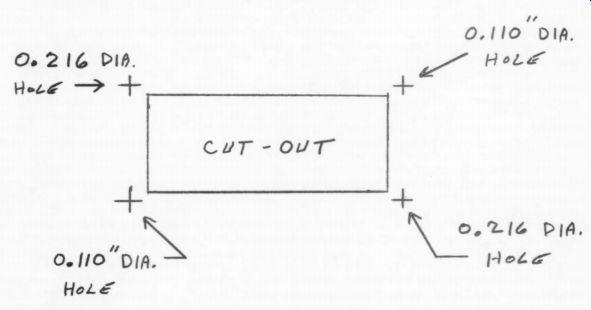
FIGURE 3: C-TON DK-605 LED bezel template, actual size.
I know this process seems tedious, but the written description is more complicated that the actual process. The fixed-value metal-film resistors will provide better calibration accuracy than a pot over time and temperature.
Place four rubber stick-on feet on the bottom cover as a final touch.
DPM Alternative
After completing this project, I discovered a much less expensive alternative to the C-TON DPM. Hosfelt offers a 3 1/2-digit LED DPM (P/N PM-129B) that operates on 5V, but its full-scale input is 200mV. At first glance, I see no reason why it wouldn't give good results compared to the C-TON DPM. If you use this DPM, the sheet metal cutout and mounting will be different, and you'll need to rescale RS and R6 to conform to the 200mV maximum input requirement.
I hope your AC Power Line Monitor proves to be a useful addition to your test bench.
-Frank Mee
Also see:
On The Mechanics of Tonearms, Part 1
A CASE STUDY IN AUDIO AMP DESIGN: THE A40M, PART 6
Just looking (Four, 1989)