Here's a simple circuit module that allows you to easily plug in voltage regulation wherever you need it.
This module is intended for use as a sub-circuit in electronic systems such as op-amp-based audio circuits requiring dual (positive and negative) supply voltages. If you are building active filters, crossovers, equalizers, pre amps, or the like, simply allow room on your circuit board for a 5-pin SIP connector (or a row of five 0.040"-diameter holes) with a little surrounding space for the module PCB (Fig. 1).
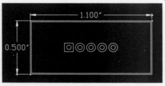
Fig. 1 PCB footprint
Circuit Description
The module is based on the ubiquitous LM317T and LM337T positive and negative adjustable-voltage-regulator ICs. The ICs are thermally and short-circuit protected, so they are nearly indestructible. A quick check of the schematic (Fig. 2) reveals the simplicity of the circuit.
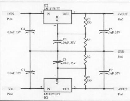
Fig. 2: Schematic of dual-voltage reg. module.
There are filter/bypass caps at the regulator inputs, a pair of resistors to set the output voltage of each regulator, output filter/bypass capacitors, and ripple-rejection caps. All the capacitors are tantalum, rated for 35V operation. The parts are listed in Table 1, and the specifications in Table 2.
The resistors set the output voltage according to the following formula:
V_out =1.25 x (1 +R2/R1) or, solving for R2,
R2=R1 x (V_out - 1.25)/1.25.
Note that the resistors are the same whether setting the voltage for the positive or negative regulator.
You need not set both regulators for the same output-voltage magnitude. One can be set for +15V, and the other for -6V, or any other combination of positive and negative output. Just install the appropriate resistors for the voltages you wish. Table 3 shows resistor values for standard 5% carbon resistor combinations and the resulting voltage output. I chose the 330-Ohm resistor so the voltage-setting resistors would always load the regulator chip with at least 3.5mA, the minimum specified load current for the ICs.
The regulators themselves are not limited to 30V output. They actually float above ground, so you can use them for higher voltages. If you intend to use the regulator for higher voltage output, you must change the capacitors for higher voltage-rated units and recalculate the resistor values.
------------
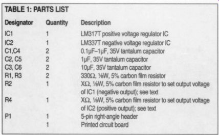
TABLE 1: PARTS LIST
--------------
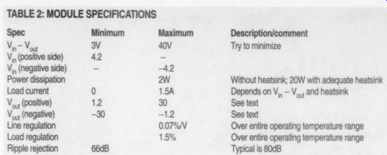
TABLE 2: MODULE SPECIFICATIONS
-------------
Description/comment
Try to minimize
Without heatsink; 20W with adequate heatsink
Depends on V_in - V_out and heatsink
See text
See text
Over entire operating temperature range
Over entire operating temperature range
Typical is 80dB
-------------
Assembling the Board
You should assemble the board with the components mounted on the top side (Photo 1). Be sure you position the voltage regulators and capacitors correctly.
Insert the regulators on the bottom side of the board (Photo 2). Tantalum capacitors become noise- and smoke-emitting capacitors if you put them in backwards.
The long lead is the positive one. Since the board is crowded, it is easiest to assemble if you start by installing components near the center and then work your way out toward the edges. Photo 3 is a top view of the assembled board.
There are several options for mounting the regulators. First, you can mount them so they extend upward as shown in Photo 3. Second, if your project case has little vertical space available, you can mount them so they stand at right angles to the PCB. Either of these positions allows you to install heatsinks if you need them. The third option is to bend the regulators down parallel with the PCB, but taking care not to short-circuit any PCB traces with the metal tabs on the regulator packages.
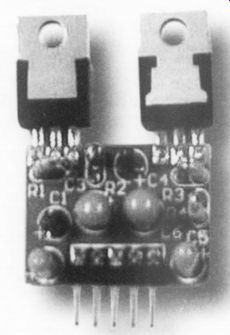
----- PHOTO 1: Top side of the PCB. Note that the square pad at pin
1 of J1 is toward the left side. All components except the regulators are
inserted on this side of the board.
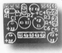
PHOTO 2: Bottom side of the PCB. Note that the square pad at pin 1 of J1
is toward the right side. Regulator ICs are inserted from this side.
---------
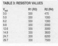
TABLE 3: RESISTOR VALUES
-------
Using the Regulator Module
The module has some limitations of which you need to be aware. Power dissipation, voltage drop, and load current all affect the operating temperature of the regulator ICs. In general, it is best to keep the voltage drop (V, - ) as small as possible (about 4V).
The thermal resistance from the package to the transistor junctions in the ICs is about 50°C/W. The regulator chips will shut themselves down if they become too hot, so try to keep the power the regulators dissipate under about 1.5W each. If the load draws 100mA, and the voltage drop across the regulator (V_in - V_out) is 10V, the regulator will dissipate 1W, and it will become warm.
If you add heatsinks, the regulators can dissipate up to 20W each, but if you use them, be sure the metal tabs on the regulator packages are electrically insulated from one another. Don't just bolt both the tabs to one piece of metal, or you will destroy the regulators.
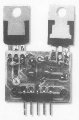
PHOTO 3: Assembled board viewed from the top side.
Also see: