It is recognized that most studio operations are concerned with turn tables and magnetic tape or tape cartridges. The major part of an operator's duties are concerned with prerecorded shows. "Live" studio programs normally are recorded on tape for playback at a later date. Whether a pro gram is recorded on tape or aired live, the operator must be familiar with the proper operational techniques involved.
Different techniques are used for recording or airing stereo pickups than for monaural programs, even with compatible stereo. It should be under stood that the term "compatible" applies to monaural-stereo receivers, not to pickup and recording techniques.
11-1 BASIC DUTIES OF THE OPERATOR
A good studio operator ( whether an announcer/operator or operating engineer) must be very sensitive to art as well as science in broadcasting.
It might appear that the art is overemphasized in the following pages; in reality, however, it cannot be overemphasized.
Broadly speaking, there are three kinds of program sources which concern the control-room operator:
1. Studio--This may be turntables, tape, or an actual studio performance to be aired or taped. The operator may be required to announce in addition to operating the equipment.
2. Remotes--These are pickups originating somewhere other than the studio, such as at a sporting arena, night club, or other location.
3. Incoming network program. In nearly every case, the operator must also maintain the station program log. Where remote control of the transmitter is authorized, the transmitter readings specified by the FCC are logged at the specified time intervals.
For studio programs, microphones must be set up, or "spotted," in the studio in such a manner that all musical instruments and performers will be adequately covered. Microphone output is very weak and must be amplified sufficiently to be carried by wire lines to the transmitting plant.
(This is true in all cases except where the transmitter and control rooms are installed together. Even in this case, the signal must be amplified considerably to drive the speech input stages of the transmitter.) Control of the various microphones is provided by the control console. A volume indicator must be used to indicate the relative magnitude of the program signals; it is mounted on the control console in an area convenient for viewing by the operator.
Fig. 11-1 is a view of the ABC production control room at Pittsburgh station KQV. The window looks into the studio for disc-jockey operations.
Courtesy American Broadcasting Co.
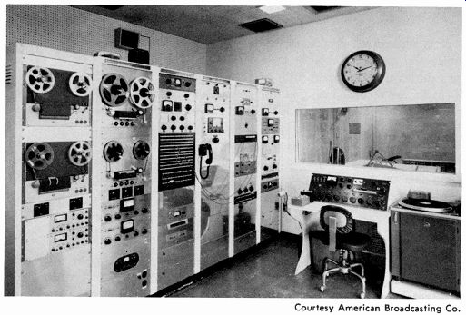
Fig. 11-1. Central production area at KQV, Pittsburgh, Pa.
One duty of the control operator is to place the microphones in the studio where the production director wants them for a particular program.
If no production director is employed, the control operator must determine the positions of the microphones, or perhaps more correctly stated, he must determine the positioning of the performers in the microphone pickup area. The best positions are usually determined only by rehearsing the show before air time and changing the respective positions until the proper pickup is achieved.
During the progress of a studio show, the studio operator's position is at the control console. It is his function to operate the various controls so that the respective microphone outputs blend properly to give the effect desired.
When a production director is employed at a station, he will assist the operator by telling him which sound or sections of sound to bring up or lower.
Since, in any transmission system, definite limits exist as to maximum volume that can be handled and minimum volume that is adequate for transmission, the overall volume must be monitored and controlled by the operator. This is the purpose of the volume indicator. The operator must also operate the switching system to choose the proper studio or incoming pro gram lines.
11-2 YOU'RE UP AGAINST SOUND
The control operator must be familiar with one of the most complex and perhaps one of the most controversial scientific fields, the field of sound. Since he must correlate the known facts of sound with operational techniques of equipment (even though only recordings may be involved for a local announcer), it is important here to review some fundamental principles.
Whenever the air is set in motion at a vibratory rate that happens to fall within the audible range of the human ear, we hear sound. This sound, in the strict physical sense, is a setting up of vibrations that consist of alternate condensations and rarefactions of the air. These variations in the air density constitute sound waves. The engineer or technician concerned with the transmission and reproduction of sound finds himself faced with problems of unwanted noise, loudness, tone color, and the more complex timbre.
He may read somewhere that it takes about 5 seconds for a sound wave to travel a mile in air, that it travels four times this fast in water and almost fifteen times as fast through iron, but this picture of sound does not help him in any practical manner. He is taught in his physics courses that loudness depends on the amplitude of the air disturbance and that pitch depends on the vibratory rate of the sound wave, but in practice he finds many more variables than these fundamental truths of loudness and pitch.
He soon becomes aware of a decided difference between loudness and volume.
Essentially, the reader is interested in the best possible methods of transmitting or reproducing sound, and the proper care, maintenance, and re pair of the equipment involved. He knows that the sounds he hears in nature are very definite and distinct in themselves, that the rustle of dead leaves sounds different from the rumble of thunder. He is able to tell the difference between one person's voice and another, and even to interpret the very spirit that lies behind the inflections of a spoken word. The amplifier with which he is concerned must be fed with electrical impulses which may again be reconverted to all these original characteristics that are so much a part of the original sound in nature. This section, therefore, deals with the conversion and reconversion of sound.
Fundamentals We usually think of sound as something we hear. Since this is the most practical approach to a highly complex phenomenon, we will approach the subject in relation to the effect of vibrations in the air on our hearing sense.
The physicist and the laboratory technician consider the word "sound" to mean vibrations that are set up in the air or a solid by vibrations of the original sounding body, even though there is no ear to hear that sound.
However, a broadcast technician or recording operator wants to be able to visualize the nature of his equipment as it affects the ear of the listener.
For example, what could be the various causes of amplitude distortion in a microphone? What would affect the frequency response? If the characteristics of a particular microphone in normal operating condition are known, how can these particular characteristics best be used to achieve the utmost possibilities within the natural limitations of the microphone? In order to gain the feeling and the "know-how" with sound-converting apparatus, we will start with the fundamental nature of sound and the problems associated with the conversion of sound to electrical impulses in such a manner that the ear will be able to hear the reconverted sound as an almost exact duplicate of the original impulses. Sound, of course, may be transmitted in liquids and solids equally as well as in gaseous matter, but this text will be concerned with the nature of sound waves in air, which is the primary concern of the reader.
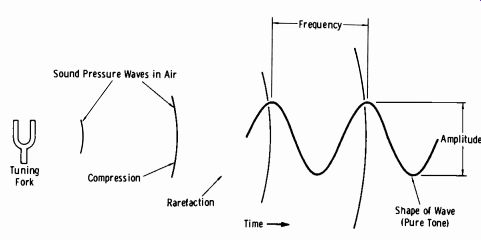
Fig. 11-2. Sound pressure and waveform produced by tuning fork.
Fig. 11-2 illustrates the fundamental principle of a sound wave. When a tuning fork is struck, it is set into vibration at an amplitude depending on how hard it was hit and at a frequency depending on the physical dimensions of the fork. As the fork vibrates, the air surrounding it is disturbed, and alternate condensations and rarefactions of the air occur. The waves travel in all directions from the fork and decrease in amplitude in proportion to the square of the distance from the vibrating fork. If these variations of the air pressure are charted with respect to time, a curve of the sound wave is obtained. The amplitude of the sound wave is represented as the overall height of the curve, and the frequency is represented by the distance between successive peaks or troughs of the curve plotted against a definite time axis. For example, if the time between successive peaks is one-thousandth of a second, the curve represents a tone of 1000 Hz.
Insofar as pure tones such as those from a tuning work or audio oscillator are concerned, it may be stated that the intensity of the sound is dependent on the height or amplitude of the wave, and the pitch of the sound is de pendent on the number of wavelengths per unit of time or frequency of the wave. Note the amplitude of the sound wave has been defined as intensity, not loudness; the loudness of any sound wave is a more complex phenomenon.
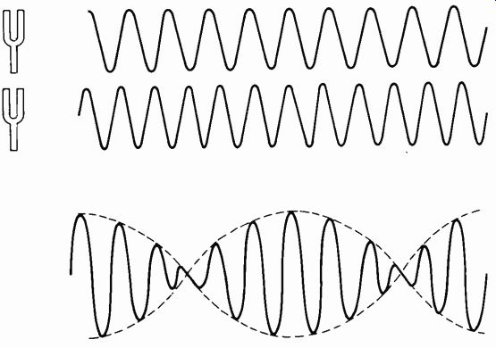
Fig. 11-3. Beat note produced from two fundamental frequencies.
Now consider what happens when two pure tones of different frequency are sounded. Fig. 11-3 shows two tuning forks, the individual waveshapes, and the resultant waveshape when the two are combined in the air. When the two waves are in phase (both rising and falling together), the resultant wave is additive and a large amplitude results. When the waves differ in phase (one rising, the other falling), they tend to cancel out and the resultant amplitude is small. This physical growing and dying out of sound at regular intervals constitutes a beat note, which is equal in frequency to the difference between the two original frequencies. For example, if fl = 2093 Hz and f2 = 2349 Hz, the beat frequency would be 256 Hz. In this case, the ear would hear not only the two real physical frequencies, but also the beat of 256 Hz. If a physical analysis of this tone is made, it will not reveal any wave component of 256 Hz, yet this sound will be just as real to the ear as are the two fundamental tones. Such tones have a great influence on quality as interpreted by the ear.
This tone quality, or timbre, of sound is related to the shape of the wave.
For instance, a flute sounding the tone of middle C (261.63 Hz American Standard Pitch) will not sound the same as a clarinet sounding the same frequency. We still recognize one sound as being distinctly that of a flute and the other sound as being distinctly that of a clarinet. Fig. 11-4 is a graphical representation of these two sound waves, showing why the timbre, or tone quality, differs as interpreted by the ear, even though both tones are of the same frequency.
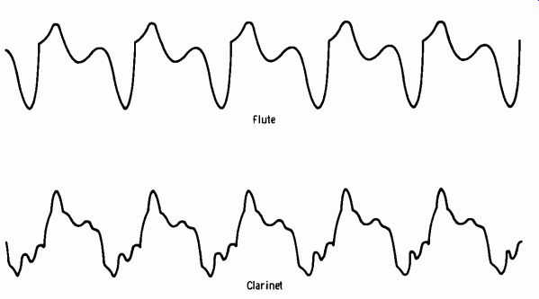
Fig. 11-4. Waveforms of two wind instruments.
In practical use, a microphone is subjected to a wide variety of tones that make up the character of speech or musical sound. These waves be come very complex in character and are termed complex waves. When a word is spoken, the sound is given a certain timbre, or tone color, that is determined by the vocal chords, mouth, and nasal cavities of the speaker.
This characteristic of speech is like the fingerprint of a person; no two people have exactly the same voice timbre, and this is the reason why we can recognize a person's voice even when we are blindfolded. For fidelity reproduction, as in broadcasting, any gateway to sound must be able to convey the different shades of expression of voice or music. In the case of the disc recorder head, for example, it must convert electrical vibrations into corresponding mechanical energy sufficient to move the cutting needle.
The pickup head must convert the energy of the needle in the grooves of the record to corresponding electrical vibrations to excite the amplifier.
All of this must be accomplished so that the original shapes of the sound waves which determine timbre or tone quality are maintained as accurately as possible.
The Phenomenon of Hearing
The understanding of any apparatus connected with sound transmission necessitates a knowledge of human hearing. The previous paragraphs have dealt with the mechanics of sound in air, and how these waves must be handled to be used for transmission or reproduction. In the final analysis, however, the ear, or rather the interpretation by the ear, is the basis of all practice and theory in the practical field of sound.
The frequency response of an excellent ear is from 20 to 20,000 Hz. The range of the average normal ear is generally taken as 20 to 15,000 Hz.
There is, however, a noted falling off of high-frequency response with advancing age.
When you think of response, consider the effect of differing frequencies on the hearing sense. When it is said that an ear responds to a frequency range of 20 to 15,000 Hz, it is not implied that the ear responds to a frequency of 40 to 50 Hz equally as well as one of, say, 1000 Hz.
Review for a moment the graph of Fig. 2-16, Section 2, which shows the frequency and volume range of speech and music. The lower curve, showing the threshold of hearing, is a picture of the deviation of response of the ear with frequency. That is, if the 1000-Hz tone is taken as zero dB and is of such intensity that it is barely audible, a 100-Hz tone must be approximately 40 dB to be barely audible. It is seen here that there is a notable falling off of both the low-frequency and high-frequency response when the sound intensity is low. When the intensity is so high that it approaches the threshold of feeling ( upper curve) , the frequency response of the ear is seen to constitute a comparatively flat line. It can also be ob served from this illustration that the frequency range of speech is 100 to 8000 Hz, with a dynamic range ( ratio of lowest to highest intensity) of 40 dB. The frequency range of music (in this case, an orchestra) is about 40 to 14,000 Hz with a volume range of 70 dB. There is a definite effect of frequency range on the intelligibility of speech and the quality of speech and music.
Loudness
It should be realized that loudness depends not only on intensity but also on frequency, due to the peculiar properties of the human ear. The radio service technician is acquainted with the bass-boost circuit associated with the volume control of a receiver, which boosts the bass response at low volume settings to help offset this characteristic of hearing. In actual practice, it may be noticed by the broadcast operator that two voices producing the same indications on the volume indicator will sound different in loudness. The loudness of a complex wave depends on the number of harmonics present in the sound wave, and on the phase relationships of these harmonics. Since the content of voice waves differs so radically from person to person, the technician should realize that this effect is not an indication of a faulty component, but is a natural phenomenon of the hearing sense. It may also be understood from this discussion why a microphone, pickup, or recorder head must introduce negligible phase or frequency distortion, since the timbre of sound depends so much on the waveshape.
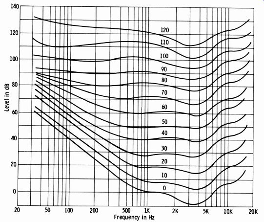
Fig. 11.5. Family of loudness-level curves.
Fig. 11-5 is a graph of loudness level curves adopted by the American Standards Association. The derivation of these curves is explained in most standard textbooks on sound and will not be duplicated here. An example will suffice to enable the reader to use this graph correctly. It will be noted, for example, that a 300-Hz tone 40 dB above the reference level (0 dB) corresponds to a point on the curve marked 30. This is the loudness level.
It means that the intensity level of a 1000-Hz tone (reference frequency) would be only 30 dB in order to sound equally as loud as the 40-dB 300-Hz tone.
Now assume a fundamental of 392 Hz (G string of a violin) with an actual intensity of 40 dB above reference level. From the curve, the loudness level is approximately 36 dB. It was determined by Bell Laboratories that the addition of the overtones or harmonics of the fundamental raised the intensity from 40 to 40.9 dB, whereas the loudness level was raised from 36 to 44 dB. In other words, the addition of the harmonics raises the actual meter reading only 0.9 dB, while the loudness level increases 8 dB.
The reference level of 1000 Hz would have to be 44 dB to sound equally as loud as the complex tone.
When it is realized that the vocal organs of human beings are all exceedingly different, and are associated with a particular resonating apparatus that gives to the voice its individual timbre, it becomes clear why two voices peaked at a given meter reading will often sound far different in loudness. Certain harmonics of the voice are emphasized while others are suppressed in an infinite variety of degrees. Fig. 11-6 illustrates waveforms of two male voices intoning the same vowel. A decided difference in peak factor (ratio of peak to average content) depends to a large extent on the harmonic content and the phase relationship of the harmonics to the fundamental.
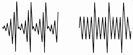
Fig. 11-6. Waveforms of two male voices intoning the same vowel.
At the present time, only one solution suggests itself. When it becomes necessary to transmit two voices so different in timbre as to be decidedly unequal in loudness for a given reference level, the good taste and judgment of the operator at the control panel must govern their respective levels. The author fully realizes the many and varied complications that arise from this condition, since loudness is not only a physical, but also a psychological phenomenon. The level at which the receiver in the home is operated will determine the extent to which changes in loudness intensity are noticeable; at low volumes, a greater change of intensity is required to be noticeable to the ear than at high volumes. Acoustics of the studio and the room in which the home receiver is operated will influence the effect of intensity changes on the ear. However, the control operator with good taste, a critical ear, and keen appreciation of values can find the "happy medium" between aesthetics and conventional transmission operations. This is of prime importance when voice and music are to be blended.
If some kind of guideline is desirable when "gain riding" by a meter, the compression meter ( which indicates the amount of compression occur ring un the agc amplifier) should be observed rather than the output VU meter. When experience dictates that a following sound source is louder than normal programming for a given VU meter reading, ride this source for zero compression. For example, if normal programming is causing 6 dB of compression, adjust the gain on the "loud" source for no indication of compression. The output VU meter will still indicate about normal level, but the average sound level will be 6 dB lower. In many cases, a difference of 10 dB is required between various sound originations for the loudness to seem the same to the ear.
NOTE: The subject of loud commercials has now become a source of FCC rulings, which are covered in the last section of this Section. There are many variables involved, such as the amount of reverberation used and the type of filtering. Due to the wide gamut of factors involved, and the importance of this subject, we will cover these many variables before undertaking a study of the FCC rulings.
(A) Small phase difference. (B) 180° phase difference.
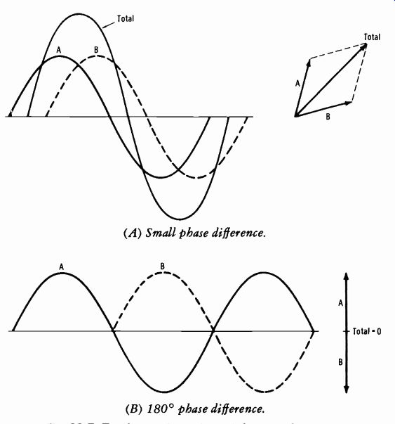
Fig. 11-7. Two harmonic motions of the same frequency.
11-3. VOLUME-INDICATOR INTERPRETATIONS
For the purpose of discussing problems relating to the use and interpretation of volume-indicator readings, use will be made of the fact that any wave, no matter how complex, may be reproduced exactly by a number of sources of pure tones. Fig. 11-7A shows two simple harmonic motions of the same frequency, differing slightly in phase; tone B lags tone A by a certain number of degrees. The vector addition shows how the total amplitude is influenced by the reinforcement of the two tones. Fig. 11-7B illustrates the same tones of similar frequency differing in phase by exactly 180°. The vector diagram shows complete cancellation of the total energy, since the tones are now opposing each other. Keeping this clearly in mind, notice that the total amplitude will be larger for smaller angles of phase difference, and if the two tones are exactly in phase, the parallelogram collapses and becomes a straight line ( that is, the sum of the individual amplitudes) . As the angle of phase displacement becomes larger, the total amplitude becomes less, until at 180° it becomes zero.
Under program conditions, a large number of different frequencies with varying phase displacements are encountered, and the loudness sensation produced in the ear for a given meter reading is dependent on the number of harmonics present and the phase relationships of these harmonics. It then becomes obvious that the acoustical treatment of the studio and the type of program content will influence the correct interpretation of a volume-indicator reading. It is, of course, apparent that the volume indicator shows the magnitude of the waveform, whether it be distortion peaks, noise, or musical sound, that must be kept within the dynamic range of the transmission system. But when the reading of the volume indicator is correlated with the effect produced on the hearing sense of the listener, these problems must be met and analyzed. The loudness sensation for a given meter indication has already been discussed with regard to voices of different persons. The same characteristic is noted between individual musical instruments where the number of harmonics and their phase relationships may vary widely.
The volume indicator is used as a means of visually monitoring the magnitude of program waves for two primary reasons:
1. To compress the original wide dynamic range to an amount consistent with good engineering practice of the broadcast transmission system.
2. To locate the upper part of the dynamic range below the overload point of associated equipment.
For the latter purpose, a scale of 10 dB would be adequate; for the former, a much wider decibel range is desirable. Since the instrument is used for both applications, it was decided that a compromise on a scale length of 20 dB would be desirable. It appears that as the art and appreciation of high-fidelity service advances, not only the frequency range but also the dynamic range of transmission will be extended, particularly for certain types of program material. This feature becomes very important in fm service. With present-day meters, it is left to the experience and judgment of the operator as to how far the volume should be allowed to drop below the visual indication of the VU meter.
In practice, pure sine waves are not broadcast, except for special testing purposes. Program waves, whether speech or music, consists of relatively short bursts of energy with variously spaced peaks and valleys. The standard VU meter is characteristically damped such that the relatively sharp peaks in program audio cannot be indicated. Essentially, this meter shows a kind of average of program audio, and actual program voltage peaks exceed the resulting meter deflection.
(A) Program and sine wave peaked at 0 VU indication.
(B) Program overmodulation with gain adjusted for sine wave.
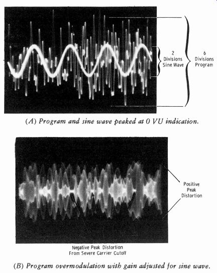
Fig. 11-8. Oscilloscope displays of program waveforms.
Fig. 11-8A shows an oscilloscope display of a sine wave (arbitrarily adjusted for 2 divisions on the graticule) and the superimposed program audio signal when the VU meter indicates 0 VU (100-percent reference) in both instances. An, oscilloscope displays actual voltage peaks; the VU meter (even any so-called peak-reading meter) does not. The actual peak-to-peak excursion of program waves in Fig. 11-8A covers 6 divisions, for a three-to-one voltage ratio, or about 9.6 dB. In practice, depending on the program content, this ratio of program peaks to sine-wave voltage at the same reference VU indication can be anywhere between 8 and 14 dB.
This characteristic is very important to the studio engineer and transmitter engineer when the procedure of setting levels is involved. For ex ample, if you operate the transmitter by remote control and you feed a sine wave at 100 percent reference on the VU meter, do not be concerned that the transmitter modulation monitor indicates only around 32 percent modulation when the input gain was previously set for 100-percent modulation on program.
If you make the mistake of adjusting the transmitter input gain to result in 100-percent modulation when the VU meter indicates 100-percent sine wave reference, you will have severe overmodulation of the transmitter when you apply program. Fig. 11-8B shows the result of this type of error.
The subject of correlation of meter readings between transmitter and studio will be covered more fully in Section 14. This is done primarily to keep the subject matter closely linked to the type of operation at hand, even though many installations use combined studio-transmitter operators because of transmitter remote-control operation.
11-4. MECHANICAL OPERATIONS
In the realm of the physical, mental, and psychological faculties of the control-room operator lies the success or failure of the broadcaster's daily schedule. A script-writer's masterpiece or a composer's dream can amount to no more than the original worth of his work, plus the ability of the control operator to interpret that work on the technical equipment at his command. Yet, perhaps paradoxically, the best qualified operators are the least conspicuous to the listener at home. This statement is just as applicable to operations in a so-called "automated" installation.
An ideal job of turntable and tape operation or switching and blending of microphones for the various performers of a given show is such that the listener is entirely unconscious of mechanical operations necessary to their performance. The operator who cuts his program at its conclusion, instead of fading out (even though because of time limitations it must be a quick fade), not only makes mechanical operations apparent to the listener, but marks himself as a man not entirely a master of his equipment.
Exceptions to this rule exist, such as stunts of a technical nature that are sometimes aired to impart a technical flavor to the layman. In such pro grams, operations should be accentuated, of course, rather than subdued, but it is well to remember that, as a general rule, the test of the operating technique should be, "Are mechanical operations apparent?"
Music, speech, or background accompaniment that is too high or too low in level should be gradually adjusted to normal in a manner cognizant of musical and dramatic values. It might appear, at first, that this prime requisite for good operating practice would conflict seriously with good engineering practice. When levels are too high, overloading of associated equipment at the transmitter occurs. When compression amplifiers are used, as is commonly the case, distortion arises from excessive compression rather than from overmodulation of the transmitter. It has been proven from extensive tests, however, that distortion caused by momentary overloads simply is not noticeable even to highly trained ears. This appears to be due to physiological and psychological factors that determine the response of the ear to aural distortion, resulting in a lack of response to overload distortion of short duration and occurring at rare intervals.
The level of the speaking voice can be least obviously adjusted by correcting the fader setting between words or sentences where slight pauses occur, rather than increasing or decreasing the volume during actual excitation of the microphone. A comparison of these two methods by the operator on his audition channel will reveal the striking obviousness of level control; the former technique allows less conspicuous adjustment.
Anticipation can play a major part in smooth level control when circum stances permit. The operator soon becomes familiar with the approximate fader setting for each announcer, or for his own voice relative to a preceding one if he is a combination announcer-operator. It is obvious here, of course, that ample opportunity to adjust the mixer gain is needed before actual air time. This is also possible in some instances with transcribed and recorded shows, when the operator is aware of the brand of recording to be played next. This will also be influenced to a great extent by the type of filter used on the turntable for various recordings, since a different filter is used in many instances for different brands or conditions of recordings and transcriptions. The gain settings for a given brand will usually be fairly consistent. Thus, when the operator has become familiar with the necessary fader adjustment for each brand of transcription or recording, he will be able to use the art of anticipation to good advantage. However, if uncertain of the level, it is well to remember that from an aesthetic as well as a technical point of view, it is far better to fade in the speech or music rather than to experience the shock of excessive volume which must be quickly lowered to normal values.
The foregoing discussion is likely to lead to an erroneous point of view on the part of a newcomer in a control room. One of the most common errors of new men in this field is to ride gain to the point of exasperation to a critical listener. The operator should endeavor at all times to give musical and dramatic values a free rein insofar as is practically possible.
Remember that from the listener's point of view, the business and purpose of broadcasting is to provide entertainment by bringing music and dramatics into the home. The technical setup necessary for this purpose has been engineered to a point of perfection; it is only necessary that this equipment be operated in a manner that will promote musical and dramatic values in their original intent.
The fundamental rule of good operating technique is probably the most abused by innocent operators during the transmission of symphony broad casts, live or recorded. Suppose that an orchestra of 40 to 80 members has just finished a number which for the past few minutes has been pianissimo (soft), say-15 to-20 VU. It is safe to say that the average listener to a symphony program will have his receiver volume adjusted so that comparatively high power exists in the speaker when the studio level reaches 0 VU. It is obvious then what will occur if the announcer suddenly starts speaking at a 0-VU level. The listener may not be actually raised from his chair by this sudden roar, but the experience is quite unpleasant. Sudden crescendos in music are expected, welcomed, and appreciated, but a single announcer at an apparently greater volume than an 80-piece symphony orchestra simply is not only unwelcome, but extremely obnoxious.
It is a safe rule to remember that after such musical numbers as this, the announcer should be held down to about-6 VU maximum. The difference to be maintained between levels of voice and music will depend not only upon the type of program aired, but also upon the acoustical treatment of the studio where the program, live or recorded, originates.
The inadequacy of present-day broadcasting in the field of symphonic music transmission is quite apparent to most engineers. The discrepancy between the usual 70-dB dynamic range of a full orchestra and the actual 30 to 35 dB allowed by broadcast equipment is all too obvious to the control operator handling such pickups. It has been the practice of some operators who do not appreciate the symphonic form to bring all low passages up to around -4 VU, and then reduce the gain as the orchestra increases its power according to the continuity of the musical score. The fault in this technique should be apparent. If the very lowest passages are brought up to just "jiggle" the meter, and care is taken to use good taste in suppression of the crescendos, a satisfactory dynamic range may be experienced, since even a range of 25 dB will vary the output at the receiving point from 25 milliwatts to nearly 16 watts on peaks.
The technician on a symphony, or any musical program, should possess a good ear for music. Rules and regulations will never help a man with a pair of "tin ears" to handle a musical show properly. It is, nevertheless, important that the transmitter technician (if separate from the studio) under stand that a great amount of modulation during classical music will be below 20 percent even with compression line amplifiers.
Recordings and transcriptions of symphonic music have already been compressed into the broadcast dynamic range, since the recording engineer has essentially the same problem to contend with in relation to this difficulty. Usually all that is necessary for the control technician to do is to set the peaks of the music to 0 VU or 100 on the scale, and "let it ride."
Don't Be Hypnotized
The foregoing discussion should serve to warn both newcomers and old timers against one of the most common occurrences in control rooms-the hypnotized operator. A volume indicator is apt to exert a strong hypnotic effect on the person responsible for "riding gain" on a program. So long as the meter peaks at 0 VU, or 100 percent, on the scale the suggestion to the subconscious mind that all is well is almost overpowering, in spite of the aural reaction that ordinarily would warn the operator. Competition in the field of modern operating technique demands more and more coordination of aural effects and volume-indicator interpretations.
The rule here is to train the aural response to command attention over and above the VU-meter indication. If a certain voice sounds low in volume in relation to the music, peak the music just enough lower than the voice to compensate for this effect. If two or more voices on the same program sound different in loudness, balance them aurally, then note the respective VU-meter readings. It is quite often possible to alter the loudness sensation of a particular voice by changing the distance from the microphone or the angular relationship to the axis of the microphone.
-------------
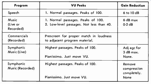
Table 11-1. Suggested Program Transmission Standards
Program VU Peaks Gain Reduction
Speech 1. Normal passages. Peaks of 100. 6 to 10 dB Music (Live or Recorded)
1. Normal passages. Peaks of 100.
2. Low-level passages. Not less than 40.
6 dB max
0-2 dB Commercials (Recorded)
Prescreen for proper match in loudness to adjacent program material.
Symphonic Music (Live) Highest passages. Peaks of 100.
Pianissimo. Just move VU.
Adj agc for 3 dB max.
None.
Symphonic Music (Recorded) Highest passages. Peaks of 100.
Pianissimo. Just move VU.
Remove compression completely.
None
------------
The amount of compression of the agc or compression amplifier affects the loudness to the extent of raising the average volume level of transmission. Table 11-1 lists suggested audio program transmission standards and serves as a guide for radio operators. Note that the gain reduction (decibels of compression) is considered along with VU-meter peaks. In the individual station, where management permits, the operator is under a far more flexible set of rules which allows consideration of "loudness sensation" in gain adjustments.
Keeping Sound "Out of the Mud"
The problem of correlating volume levels with comparative loudness of speech and music has appeared as an item of major importance and should not be ignored by broadcast station personnel. As was mentioned before, because of the nature of classical music, the symphony listener at home will operate his receiver a great deal higher in level than he would for ordinary programs. Five minutes of symphonic music will have perhaps 3 to 4 minutes of low to very low levels; the average intensity level over a period of time is far lower than the average intensity level of a dance orchestra in the same time interval. It should then be obvious that a greater difference should exist in the ratio of music to speech levels for symphonic programs than for those of dance music.
The acoustical treatment of the studio in which the program originates affects to a great degree the loudness of voice and music, and in a different ratio. A studio that is over-treated with absorbent material deadens the sound because of high-frequency absorption and is an outstanding enemy of musical programs. Music from "dead" studios is "down in the mud," lacking in brilliance, and generally dull to hear. The effect on speech, however, is not so pronounced as that on music. Speech originates within a few feet of the microphone and requires much less reverberation to assure naturalness, whereas the space between the source of the music and the micro phone is greater, and many things happen to the musical waveforms that must eventually be translated into perceptions of loudness.
So-called "optimum reverberation time" really is an expression of what constitutes pleasing sound, and it changes with experience. It may well be that standards of optimum reverberation time in the near future will decidedly alter the preceding discussion of ratio in peaking voice and music.
The point that is important to keep in mind is that a great majority of studios throughout the country are below today's standards of correct reverberation characteristics.
The newer "live-end, dead-end" studios, with musical instruments placed in the live end and microphones spotted in the dead end, present one solution for properly controlled reverberation. In these studios, voice and music peaked at the same level will appear the same in loudness sensation. In fact, the advancing state of studio development indicates a transitional era during which the brilliance of music is so great in some of the most modern studios using reflecting panels for musical pickups, that when the music is peaked the same as voice, the voices sound much lower in loudness than the music. This brings to mind again the importance of using judgment in aural perspective when riding gain on productions with the intent of achieving a properly balanced effect when the program is reproduced in the listener's home.
11-5. TECHNICAL PRODUCTION TECHNIQUE
This text is concerned with the type of productions normally encountered in the average AM or fm station. More complex productions, such as those requiring many tracks of tape channels which are "mixed down" to a one- or two-track format (as is done in professional recording studios) , are not considered.
Principle of Microphone Patterns
In determining the placement of microphones for any given setup, it is important that the operator become familiar with the pickup patterns of the microphones used. These patterns illustrate the amplitude response for varying directions about the face of the microphone. Fig. 11-9A shows the pattern of the RCA 44-BX velocity microphone, and Fig. 11-9B is the pat tern of an RCA 77-B combination ribbon- and pressure-type instrument.
There are several important points of interest relating to these patterns which show great differences in characteristics aside from the most apparent one, that of bidirectional pickup by the velocity type and unidirectional pickup by the combination type.
An analysis of the patterns reveals a much wider range of amplitude response for the combination pressure-gradient (ribbon) and pressure microphone than for the ribbon type alone. It is noted from Fig. 11-9A that at an angle of 70° the amplitude response is down about 10 dB with respect to the response at a given distance at 0°. Now note from the response curve of Fig. 11-9B (combination type microphone) that the amplitude response at 70° is down only approximately 3 dB from the 0° reference.
These patterns are useful for determining the setups necessary for discriminating against unwanted sources of sound, and for obtaining a particular relation between sounds from different sources. It can be seen that as a performer is moved around the microphone, loss of sensitivity may be compensated for by moving closer to the instrument.
(A) Bidirectional. (B) Unidirectional.
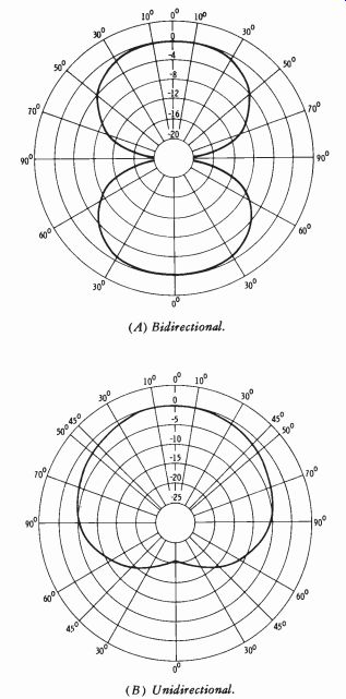
Fig. 11-9. Amplitude response of microphones.
Microphone Placement
"The microphone is a mechanical extension of the human ear." This statement is purely a fancy. The fault in this definition lies not so much in the literal meaning as in the implications that are involved. Were it true, even if we had only one ear, we could walk into a studio or on a stage and place the microphone at the spot where the one good ear could hear the orchestra, the soloist, the chorus, and the announcer. It won't work. Yet this conception is probably the contributing factor in the reasoning of an opera tor who places a microphone and proceeds to handle the show by "riding gain." Of course, there is the more ambitious type who spots a microphone for each section of the orchestra, then one for the soloist and announcer, and several for the chorus. Granted that there are some cases (particularly encountered in remote pickups) where this is necessary, it will be made clear in discussions to follow that this condition is the exception rather than the rule for regular broadcast studios.
Why is it that a microphone cannot be treated as an extension of the human ear? To understand this it is necessary to review a fundamental theory that is an old story, but absolutely essential to understanding the microphone from an operational point of view.
Unlike the human hearing system, which is binaural ( two-eared) , the microphone is monaural (one-eared); this is true regardless of the number of microphones used to feed one channel. Whether one microphone or ten is used, the sound is collected into one channel and received through one speaker. Physically, the difference is that in a monaural system the sense of direction is lost, while reverberation is somewhat more noticeable; this makes the apparent distance of the sound source seem greater than it does when the sound is heard binaurally. Any operator who has ever set up a microphone in a particularly live hall has experienced this phenomenon.
He is able to hear quite clearly the conversation of two people somewhere in the hall when listening with his two ears, but when he listens with the headphones through the amplifier, the sound seems much more distant, and extraneous noise is very high. This brings up an all-important psychological factor closely linked with the above physical one.
This psychological factor is the unconscious ability of focusing power when listening binaurally, or even with one ear plugged as much as is physically possible. The ear, associated as it is with the nervous system and the brain, tends to exclude extraneous noise that is present and focus attention on particular sounds. The microphone is a mechanical device not associated with any means of concentration except as it may be deliberately used to achieve a desired result in the listening ear at home.
A practical example is familiar to anyone who has dined in a public place where, for instance, a small orchestra renders dinner music. The table may have been out in the center of the room, and although the usual clatter of dishes, hum of conversation, and all the various noises were quite notice able, the music may have been found very enjoyable when the diner cared to listen. Yet it takes little imagination to realize what the result would be if a microphone were placed at this same table. Very little of the music would be heard, and the few strains coming through would sound far, far away. The pickup would be nothing but a hopeless hodgepodge of voice, noise, and confusion.
First, do away with the misleading idea that the microphone is a mechanical extension of the human ear. Think rather of the microphone as an instrument that must be used according to its characteristics and within its limitations to achieve an exact replica of the original program content in the listener's ear. Another statement heard occasionally is, "Microphone technique is different for fm that it is for AM." This is still a somewhat controversial subject; however, the following analysis should be carefully considered before taking the statement literally.
It is obvious that the significant difference between AM and fm is the means of rf modulation, transmission, reception, and demodulation. Many AM stations today have an audio system that is as good as that of the best fm station. Now consider only the job of the control-room operator or production man responsible for microphone setups. He will monitor the pro gram from the speaker in the control or production room, whether or not the audio signal is feeding an AM or fm transmitter. The program will sound no better in the receiver than it does in the monitor regardless of the means of transmission. It is, of course, true that the fm listeners will hear more nearly what is heard in the control room than will the AM listener. It appears then that the rule should be, "Microphone technique is somewhat more important for fm than for AM." Pattern/Studio Effects Insofar as program setups are concerned, the foremost characteristic of a microphone is its pattern of response. There are several important factors in using a microphone pattern to obtain a desired result.
The basic point to keep in mind is that a response pattern as illustrated for any particular microphone is plotted in an acoustically dead room to avoid any practical amount of reflection of sound waves. In other words, a pattern of response will hold true when not influenced by any enclosure, such as when the microphone is used outdoors. The manner in which a microphone response pattern is affected by the acoustical nature of the surroundings becomes an interesting and highly important item for the technician to consider.
In general, the pattern will hold more nearly true in a dead studio, and it will be altered more and more as the surroundings are made more live.
Take a hypothetical case of a setup involving two sound sources and a bi directional microphone. Fig. 11-10A illustrates the theoretically dead room and ideal pattern of a bidirectional microphone. Sound sources A and B are of the same intensity and are the same distance from the microphone, but B is directly on the zero-response axis. Since sound source B will excite both sides of the ribbon equally, no movement of the ribbon will result from this source, and no output voltage will be created in the microphone.
Therefore, the total output voltage will consist only of the impulses received from A. Thus, the pattern holds true.
Fig. 11-10B shows the same setup in a live room. It is still true that B will excite both sides of the ribbon equally, resulting in no response to the direct wave, but now there are reflections. Sound will be reflected from the walls back into the sensitive side of the microphone, and although reduced in intensity, the reflected sound will add to the sound from source A. The difference now between the two sound sources is one not only of intensity, but also of the ratio of reflected to direct sound. Naturally, this ratio is greater for sound source B than for source A. It is, of course, obvious that there is no such thing as a perfectly dead studio or hall. This example,
therefore, illustrates the basic idea of how acoustical treatment influences the polar response pattern of a microphone.
From this and the previous discussion can be derived three fundamental operating rules for the microphone:
1. As a sound source is moved about the microphone, loss of sensitivity may be compensated for (if desired) by moving closer to the instrument.
2. The ratio of reflected to direct sound may be raised in sufficiently live surroundings by using greater angles from the zero axis of the microphone (especially with bidirectional microphones) . The more live the acoustics, the greater will be the effect.
3. High-frequency sound sources must be more nearly "on beam" for a given distance to achieve the same intensity as lower-frequency sound sources.
(A) In dead studio. (B) In live studio.
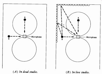
Fig. 11-10. Response patterns for a bidirectional microphone.
The nature of the acoustical enclosure about the microphone is the one factor that has most prevented any establishment of definite standards in microphone setups. If there were such a thing as a standard studio, designed to approach as nearly as practicable the ideal condition of sound dispersion, the setup for any particular musical organization would be a simple matter anywhere when once worked out. Naturally, such is not the case. It is probably safe to say that there are no two studios or auditoriums anywhere in the world that are acoustically alike.
There are, and will be, a great number of operators and producers who do not have adequately designed and acoustically controlled studios in which to work. This is an undesirable situation, but it is outside the influence of the average operator. Even some of the most recent fm broadcast installations, built in completely new studios independent of any AM company, have neglected this feature. Most of the good articles appearing thus far on microphone setups have been concerned with well-designed, musically live studios of the network centers or more production conscious in dependent owners.
The so-called "modern studio" may not yet be the ultimate in design, but it is certainly a far cry from the previous rectangular-shaped, acoustically deadened rooms. The walls remain live to musical sounds but are broken up acoustically in some manner to avoid standing waves, while still achieving a maximum response to diffused, poly-phased, high-frequency sound. Good tonal brilliance is obtained with a minimum of microphone and control-board manipulation. Recording studios have kept more abreast of recent acoustical development than have broadcasters.
Summary of Production Fundamentals
First, there is the monaural response of audio transmission. Sense of direction of the various sound sources is lost until stereophonic transmission is used. Sound perspective, then, must come from relative distances of sound sources. A sound will still appear close or distant in a monaural system. Also due to this type of response, "focusing power" must be achieved by orientation rather than by the subconscious and automatic means of the human hearing sense.
Second, strive in any microphone setup to achieve the best results possible as determined by the sound from the monitor speaker. Do not be con fused by supposed differences in AM, fm, recording, etc.
Third, bear in mind the microphone response pattern, and select one suitable for a particular purpose as explained later. Remember the influence of the acoustical treatment surrounding the pickup area on the basic pat tern of the microphone.
And fourth, it is realized that many do not have available the latest in studio design so necessary for brilliance in musical tones. An attempt will be made to help overcome this difficulty by showing what operational modifications are necessary in the older-type general-purpose studios to achieve the best results possible.
11-6. REVERBERATION When adequate sound reinforcement is not provided by the studio, several acoustical or electronic possibilities exist which may be exploited to achieve added reverberation. (Due to the special problems involved, stereo reverberation is covered in a later section.)
Fig. 11-11 illustrates one of the acoustical methods which has been used with some success and is self-explanatory. Note that the echo chamber is much smaller than that previously used for special cavern sound effects.
Since sound travels roughly 1100 feet per second in air, the 12-foot delay provides a reverberant sound of approximately 10 milliseconds. Note particularly that the lower frequencies are attenuated through the delay or reverberant channel to add reinforcement of liveness without the boominess that would occur with lower-frequency reverberation.
(A) Block diagram. (B) Relative response.
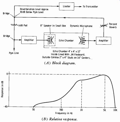
Fig. 11-11. Acoustical reverberation system.
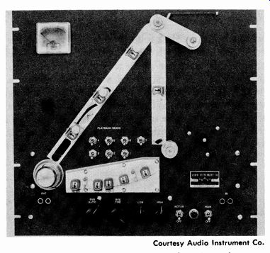
Fig. 11-12. Magnetic-tape reverberation unit.
Electronic Method
An electronic device for adding reverberation is shown in Fig. 11-12.
This reverberation unit is a tape recording system especially designed to replace an echo chamber in broadcasting and sound recording. The sound is allowed to circulate (as an electrical signal) in a closed loop formed by the multiple heads of a nine-head unit in the same way that sound circulates with multiple reflections in a room. The reverberant decay of this circulating signal is precisely analogous to that of sound in a concert hall.
The large number of heads provided allows long reverberation time with a natural overall effect.
The system is arranged to be patched between a microphone preamplifier and a mixer input, between a console output and a tape recorder, or be tween a tape reproducer and a disc recording system. It may also be wired permanently into a circuit and operated with or without reverberation.
When a note is played on a musical instrument, a fraction of the sound goes directly to the listener's ear, while some strikes the nearest surface and is reflected. The reflected sound and more of the original sound spread out, strike the next nearest surface, and are again reflected. The remainder of the original sound and the two reflection products spread out still further and are yet again reflected. The sound is attenuated by each reflection, and after a sufficient number of reflections, the sound becomes so weak as to be inaudible. Note that the sound circulates about the concert hall repeatedly, being reflected many times before it dies out. The tape reverberation device uses a process analogous to this, except that the signal is handled electronically and magnetically instead of acoustically.
The incoming signal is divided between two channels for its trip through the reverberation unit (Fig. 11-13). One portion goes through the direct-channel isolation amplifier to the output, just as some sound travels directly from the instrument to the ear. The balance of the incoming signal passes into the reverberation channel and undergoes multiple reflection in circulating about a tape-loop system. A controlled amount of this reverberant signal is fed to the output and mixed with the direct signal. By regulating the proportion of direct and reverberant signal, various effects may be produced.
Reverberation is generated as follows: A signal entering the reverberation channel passes first through high- and low-frequency equalizers, then to the recording head, and so on to the tape loop. The recorded signals are reproduced from the tape a fraction of a second later, and a controlled portion is fed back to the recording head without passing through the high and low-frequency equalizers, to be recorded and fed through again. More than one playback head may be used so that the signal may be reproduced and rerecorded several times with different degrees of delay, just as sound experiences multiple reflection (with different time intervals) from the several walls of the concert hall.
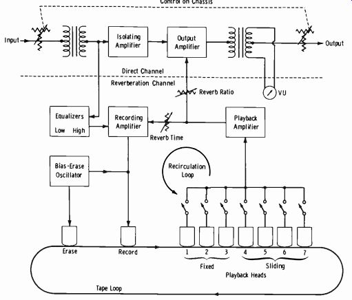
Fig. 11-13. Block diagram of tape reverberation unit.
The degree of amplification during rerecording is adjustable so that the signal may circulate many times, or only a few, around this reverberation loop before it decreases to inaudibility. By selecting the appropriate play back heads, a smooth natural reverberation decrease may be produced.
Alternatively, a single reproducing head may be used to achieve sharp echoes for special effects, or to repeat words. High- and low-frequency equalizers modify the signal which feeds the reverberation loop so that a wide variety of other effects may be obtained. The unit shown in Figs. 11-12 and 11-13 has four auxiliary heads, adjustable in position, for producing long delayed echoes, for repeating words, and for very long, natural-style reverberation.
The signal passes through an input attenuator (optional) and an input transformer and then feeds the direct channel and the reverberation channel. Both channels are then combined and fed through an output amplifier, output transformer, and attenuator (optional) . The input and output attenuators are controlled by ganged switches, providing the following combinations:
1 2 3
Maximum input level (VU) : + 4-30-30
Maximum output level (VU) : +4-30 +4
The signal in the direct channel goes through an isolating amplifier and then into the output amplifier.
The reverberation-channel signal passes through low- and high-frequency equalizers to the recording amplifier, and on to the freshly erased tape by way of the record head. The signal is reproduced from the tape with a delay that depends on which of the playback heads are in use (determined by panel toggle switches).
After amplification in the playback amplifier, the delayed signal is split into two parts. One part is attenuated in the time potentiometer and fed back to the recording amplifier for rerecording. The remainder is fed through the ratio potentiometer to the output amplifier.
It is clear that the reverberating signal recirculates through a loop consisting of the recording and playback amplifiers, the time control, and the tape-loop system, decreasing in intensity by a controlled amount with each recirculation. Because the signal makes many trips around the recirculation loop, the playback amplifier must be equalized to compensate for both head and tape response, making the frequency response of the loop very accurately flat over the required frequency range.
In general, a combination of heads 1 and 2 affords moderately short-time reverberation and is useful for adding resonance to a single voice or to a small ensemble. A combination of heads 1, 2, and 3 develops a somewhat longer reverberation time and is useful with larger ensembles. For maxi mum natural reverberation time, heads 1 through 6 are used.
The ratio control regulates the amount of reverberant signal added to the direct signal in the output; the time control regulates the rate of decay of the signal in the reverberation loop. By analogy, we can say that the latter control regulates the sound absorption of the walls of the imaginary room and its reverberation time, while the former control regulates the ratio of direct to reverberant sound (in effect, the distance between the imaginary microphone and the imaginary orchestra) .
A hasty guess may give one the idea that the controls interact. This is not correct; although both controls alter the quality of the signal, they change it in different ways. Proper setting of both the ratio and time controls is essential for good results.
Typical operation of the tape reverberation unit is as follows:
1. Set panel controls:
Head Select-Switches 1 and 2 on Time-Fully counterclockwise Ratio-Straight up Low-Straight up (approximately flat response) High-Straight up (slight rolling off of highs entering reverberation path)
2. With signal being fed into the circuit, the direct channel should deliver signal to the console fader. Advance the fader until the system output level is as desired (the VU meter should be reading 0 VU).
3. Advance the ratio control until the reverberant signal is heard.
4. Advance the time control until the reverberation becomes sufficiently apparent.
5. Further variation of the ratio, time, and equalizer controls will now produce a variety of desirable reverberation effects. The output level will increase slightly as the amount of reverberation is increased.
6. Additional variation may be secured by using other head combinations. For example, a combination of heads 1 through 6 provides the longest and smoothest average decay and is often preferred for special effects and for large instrumental ensembles. (Be sure that at least one head switch is on; otherwise hum will result.)
7. If the time control is advanced too far, the circuit will either ring or be on the edge of ringing.
8. Be absolutely certain that the input level to the unit is not over the rated value. Complaints of distortion may usually be traced to excessive input level. If in doubt, compare the panel VU meter and system VU meter readings for zero with the same input signal. On the other hand, insufficient input level will lead to failure of adequate reverberation.
9. An exactly repeated word or phrase has been found to lend force to a spot announcement. To repeat words:
A. Turn on head 5 only. Slide head 4 to bottom of track, slide head 6 to top. Turn ratio control fully clockwise.
B. Turn time knob clockwise slowly, while someone repeats the de sired word into the microphone, until the word repeats steadily (and gradually dies away) .
C. Stop the action by lifting the tape off the record head ( next to right position on 5 head block) for 2 or 3 seconds.
D. Change the repeat tempo by sliding the head carriage up or down in the slot, or by switching to another playback head. After each change of head or head position, clear the tape by holding it off the record head as above.
10. In setting up playback-head combinations, two philosophies, natural and theatrical, may be used.
A. For a theatrical effect, use one or a few heads, widely spaced.
This produces a reverberation decrease which is stepwise and prominent. The result has acquired a wide vogue in the popular recording field.
B. For a natural effect, always use heads 1, 2, and 3, perhaps plus 4, or 4 and 5, or 4, 5, and 6. The reverberation decrease is smooth, without stepwise character. Use as few heads as possible.
The longer the reverb time desired, the more heads must be used to eliminate the stepwise character. Start with 1, 2, and 3 or 1, 2, 3, and 4. Head 4 at the start should be at the bottom of its slot, the head-5 carriage should be about 1/2" away from carriage 4, and carriage 6 should be similarly far from carriage 5.
11-7. MICROPHONE TECHNIQUE
The announcer is the logical starting point for a discussion of micro phone technique. It must be understood that we are not concerned at present with announcing over a background of music or any form of dramatic presentation.
Single-Voice Pickup
Announcing alone occupies a considerable portion of the broadcaster's schedule. Correct voice transmission is very important to radio because there is no sense of sight to aid impressions; the voice is the complete medium of expression. The intake of the breath, the most subtle inflections, the style of delivery, the original voice timbre, all are factors in naturalness.
Any or all of them may be severely affected by the announcer's relation to the microphone. All of us in the technical end of radio must at some time in our career realize that our engineering training may not have encouraged a feeling of artistic values or sense of showmanship. We may be apt to lose sight of the real reasons behind the keys, faders, and perfectly matched impedance of the control system. They are designed this way so that the electrical impulses may correspond to the thunderous crescendos of Wagner's "Die Walkure" or the light, delicate strings of Debussy's "Festivals." They must reproduce the moods of music and the moods of voice. The wires and switches and dials and knobs of the technical department are concerned with these intangible qualities of human experience. If we grow ever more conscious of this in the course of our work, we will find whole new vistas of sound and sound control opening at our fingertips.
The first thing to do concerning the announcer is to get the microphone away from his face. "Mugging" a microphone is a terribly deep rut and a difficult habit to break. You will likely meet resistance from the announcer; in many cases you literally cannot do it. Some announcing desks have microphones permanently mounted on them, and the announcer cannot move back without holding his script uncomfortably in his hand with no arm rest. This is plainly and simply an engineering error. Like fingerprints, there are no two voices exactly alike. For every voice there is a definite relationship with the microphone which allows the most natural and pleasing reproduction for the combination of that particular voice and that particular microphone.
For voice work alone, there is no distance less than 2 feet from the microphone that will assure naturalness. Furthermore, a distance of 2 feet should be used only for the softest voices. Compare this with your own observations of studio operating practice. What is the distance most announcers use? Probably somewhere between four inches and a foot. Voice waves at this distance from the mouth and throat cavities do not create the electrical impulses that correspond to the natural character of that particular voice. Setting the microphone on the "voice" adjustment, if such an adjustment is incorporated, helps in cases where it is absolutely necessary to work very close (to cover up background for example) , but it is not natural transmission.
Perform this experiment if possible: On rehearsal, set up microphones (in addition to the regular announce microphone) 3, 6, and 9 feet away.
Stagger them enough so that no one microphone will be in front of an other. If the regular microphone is immediately in front of the announcer's face, move it lower or to one side. Don't tell him what is occurring; you are just "testing microphones." If he is told to start reading at a great distance from one microphone and then to move closer, he will subconsciously alter his volume and you will not get a natural check.
Now turn on only one microphone at a time. Start with the farthest one.
Unless you are so conditioned to hearing the "mugging voice" that you can accept no other, you will find a new experience in naturalness of voice transmission. A distance will be found at which the voice begins to sound "hollow" in a live studio, or "thin" in a dead one. Use a distance just a shade closer than this point.
In small announce booths where space is at a premium and where distance would create the "barrel effect" due to the proximity of the studio wall to the microphone, the microphone should be suspended over the announcer's head at a distance of several feet. This technique is borrowed from television, where the microphone must be kept out of the range of the camera and is often as much as 15 feet from a performer. It should be borne in mind, however, that the sound in television is only a secondary expression to the picture. In other words, all of the intent and meaning need not be embraced in sound alone as in radio broadcasting.
This same technique is most convenient when two persons are seated at a table and using a single microphone. The table top should be deadened to sound by acoustical treatment or a heavy cloth cover to prevent reflected sounds from entering the microphone. This is very important when the suspended-microphone technique is used.
Two or More Microphones
In studying specific program setups, the number of microphones that should be used will invariably be questioned. Always keep in mind the previous discussion on the monaural character of the system and the lack of focusing power unless deliberately used to concentrate the attention.
The greatest weakness in microphone setups for large shows has always been the use of too many. There is bound to be some distortion (however slight) in multiple setups because the time lag of sound waves creates phase additions and subtractions at the various positions of pickup. This source of distortion, however, is only minor compared to the other faults of this technique. Aside from the operational difficulties of handling a large number of channels on the mixing panel with greatly increased chances of error, the sound man and his board now share control with the conductor. All the dramatic interest, the emotional pattern written into the original score, plus even the conductor's interpretation, are now placed in the ratio of fader adjustments and depend on the reaction and psychological temperament of the operator; in other words, there are too many variables.
This is just the opposite of professional recording techniques, where as many as 12 to 14 channels are later "mixed down" to achieve the proper balance and perspective in the final recording.
Microphone Phasing
It is very important in any sound application in which two or more microphones are used fairly close together to have the outputs properly phased. If this is not done, the outputs will oppose each other, reducing the total signal and introducing some distortion. This is the same thing that happens in multiple loudspeaker systems when the voice coils are out of phase, causing a "pumping" or bucking of sound at points in the overlap ping fields of the speakers.
Ti-e best way to phase two or more microphones is to hold two in the hand at the same time while talking. Turn one microphone on and note the volume-indicator reading. Be sure not to alter the volume of the voice when turning on the second microphone with the same volume-control set ting. If the volume now decreases, the connection of one of the microphone cables at the amplifier input terminals should be reversed. Each additional microphone should be checked in this manner against the first microphone.
Phasing may be accomplished by using a patch cord between any two terminations of the circuit on the jack panel, and reversing one end at a time during the test.
How Many Microphones
Let us establish a foundation on which to build a workable structure for determining the correct number of microphones for a given show. Let us also be practical and realize that a great number of operators do not have the very latest studios and hours of rehearsal time to spend on one program.
1. Whenever it is physically possible in the allotted setup time, arrange the performers about a single microphone so that the overall balance is correct. If you have the time to do this, you achieve proper balance by positioning rather than mixing various sources on the control board.
2. Assume now that time is running out and you are still having trouble with a particular section in obtaining balance. (This is more apt to occur in a dead studio than in an acoustically correct live studio.) The use of one microphone is not achieving maximum fidelity, and an other microphone for the troublesome section will have to be used.
Many times in practice it will be found that the second pickup need be used only at times and not all through the show (such as rhythm section accentuation of an orchestra at a few spots in the score.)
3. Some of the more complex shows will positively require more than one microphone for proper pickup. Take, for example, a variety show consisting of a drama cast, a chorus, and an orchestra. Remember that the microphone does not focus attention as your ears would do in the studio. Of course, it is likely that a program of this type will originate in a larger station having modern studios and plenty of rehearsal time with the operator.
4. The rule, then, is simply this: Use the absolute minimum number of microphones for a given program and set of conditions surrounding rehearsal time.
Piano Pickup
The single-piano pickup is the simplest setup in any kind of studio since it is perhaps the least affected by the acoustical nature of the room. But there are "tricks of the trade" even in the simplest programs.
First, regardless of how softly the pianist plays (so long as he is unaccompanied by other instruments), the microphone should not be placed under the lid. Operators who have had considerable experience with using the microphone have known the amount of distortion arising from the close proximity of large physical objects to the microphone. It should then be obvious that a pickup under the lid and close to the sounding board will not allow natural transmission of the piano tones. "Close-miking" of this kind to almost any instrument will cause many "peaks" on the VU indicator that are inaudible, with a consequent necessity of holding the volume down with great loss of musical brilliance. It is true that many operators have be- come so accustomed to this type of piano setup that they are in the same position as those in the habit of hearing the close-talking announcer. It may be a familiar sound, but it is not natural reproduction.
Here is the best method of determining the setup for a single piano.
Start with a distance of 20 feet, head high. In a dead studio, this distance will probably result in a "thin" response, especially on low passages. In live studios, the sound may be too reverberant for clear-cut transmission. Move the microphone in on a line drawn through the center of the sounding board until the tones are full-bodied and just the right amount of reverberation exists. This distance is seldom less than 8 feet and will allow tonal brilliance and balance between lows and highs that is sacrificed in a close-up technique.
Now comes the final check for balance between bass and treble, in other words, the check of the player's left- and right-hand pressures. If the pianist happens to use approximately the same pressure with both hands, the above procedure is usually all that is necessary. But assume he has a heavy right hand and bass response is somewhat weak in relation to the highs. Keeping the microphone at the same distance, move it from the line drawn through the center of the sounding board toward the tail of the piano. This increases the response from the bass strings. If the pianist should have a heavy left hand causing loss of highs (this lack of highs is also apt to occur in dead studios), the microphone should be moved toward a line drawn through the hammer line of the piano, or even over to an imaginary extension of the keyboard. This will increase the response to the treble strings and decrease that from the bass strings.
Microphone
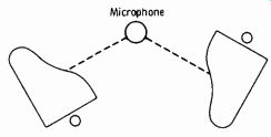
Fig. 11-14. Microphone placement for two-piano pickup.
The dual-piano team imposes only slight additional requirements. Fig. 11-14 illustrates the most satisfactory orientation of the two pianos with the microphone. The temperament of the pianists must, of course, be considered and the lead piano given prominence by moving the microphone closer to that piano if the accompanist is "heavier fisted." The above procedure for bass and treble balance must be followed by moving not the microphone, but the piano itself.
Vocalist and Piano
There are three variables in the case of a voice and piano-the distance of the vocalist from the microphone, the distance of the microphone from the piano, and the distance of the vocalist from the piano. There is no reason to use more than one microphone unless no time is allowed for rehearsal.
Listen to the vocalist in the studio first. Does he or she "sing out" with the chest muscles, using a large volume and dynamic range? Or is the vocalist the "crooner" type, using only the larynx and throat for emphasis? Generally speaking, every vocalist fits in one category or the other.
Now excluding the piano accompaniment, it is known whether the vocalist must be near to or far from the microphone. One who sings with his full volume range will be placed anywhere from 6 to 12 feet from the microphone when a piano alone is used as background. On rehearsal, always start with the greatest distance. The goal is to be able to enjoy adequately the lowest volume and the highest volume without riding gain on the fader control. This part of the balance can be achieved by careful rehearsal checks.
The balance between vocalist and piano accompaniment is not always so simple. A good pianist or one familiar with a particular vocalist's style will automatically adjust his volume to the singer. The microphone may be placed about 8 feet from the piano with the vocalist on the opposite side (calling for a bidirectional microphone) at the distance determined by trial. It is well to point out here that a very common error of operators is taking a "vocal solo" too literally. The presence of the piano must always be considered, with only slight emphasis on the voice. It should be a blend, with, of course, the voice always a little predominant. This does not permit the so often noticeable weak background of piano tones.
When the pianist insists on playing so loudly that his accompaniment smothers the vocalist (some pianists cannot alter their volume and still play well), the dead side of the vocalist's microphone must be turned toward the piano. This is practically always the only adjustment necessary from the 8-foot distance between microphone and piano. If the studio is very live and the piano tones are still too predominant, turn the piano around so that the lid opens toward a wall of the studio, and deaden the wall with drapes. Do not at any time move the vocalist closer to the micro phone, where riding gain is necessary for the natural dynamic range of the voice.
Small String Setups The music of chamber groups is intimate in style and requires good instrumental definition. This calls for comparatively close microphone setups--but not too close.
Consider a small orchestra consisting (most popularly) of several violins, a viola, a cello, a string bass, and sometimes a piano. Due to their comparative volumes, the instruments are usually placed in that order from the microphone. Fig. 11-15 illustrates the general orientation of such a group with the microphone.
Now assume that the approximate distances are: violins 4 feet, viola 6 feet, cello 8 feet, string bass 10 feet, and piano somewhat off microphone at 10 feet. Also assume that the violins are too predominant for proper sectional balance and comparative "presence." What would you do first? Here are the possibilities if you move the instruments: The violins could be moved farther back or to one side in a less sensitive zone, or the other instruments could be moved closer.
Cello First Violin String Bass Microphone Viola Second Violin
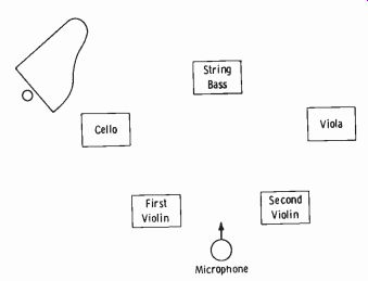
Fig. 11-15. Microphone placement for chamber orchestra.
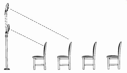
Fig. 11-16. Height and tilt adjustments.
But have you remembered the "focusing-power" principle? You can achieve quite a range of sectional balance by the simple expedient of height and tilt adjustment (Fig. 11-16). If the violins are too predominant, raise the microphone and focus on the other instruments. If the violins are weak, the microphone should be lowered and focused on the violins. This is a better method than moving the predominating instruments to one side in a less sensitive area of the microphone, since the higher frequencies containing the overtones are very important for wide-range pickups.
There is little difference in pickup for this type of musical organization between dead and live studios, since the setup must be intimate in character, with high direct-to-reflected-sound ratio. This minimizes the effect of the acoustical nature of the studio.
Small-Orchestra Setups
In the category of small orchestras are a large number of organizations presenting popular, serious, or variety music. They may consist of a combination of brass, strings, and reeds, and they may have from 4 to around 15 instruments. Again the first step is to visualize the instruments in terms of comparative power outputs, as follows (softest to loudest)
1. Violins, muted trumpets or trombones, and guitar
2. Clarinets, saxophones, xylophone, and vibraphone
3. String bass
4. Piano
5. Trombone (open belled) and trumpets (open belled)
6. Traps and bass drums; guitar (electrically amplified)
Traps Trumpets Trombones String Bass Sax and/or Clarinets Microphone
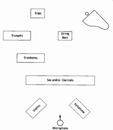
Fig. 11-17. Arrangement for small-orchestra pickup.
These are the most likely instruments to be encountered in such a setup.
As before, the most likely approach is to arrange them in the listed order from a single microphone.
Fig. 11-17 shows a live studio layout, starting with the violins at about 8 feet. When initially checking balance of sections, remember the height and tilt adjustment for focusing power to obtain the proper blend. Then, and not until then, try moving any troublesome section.
When you think it becomes necessary to move instruments, keep these principles in mind: A predominating section might be too loud not be cause the relative distance between instruments is incorrect, but because the microphone is too close to the entire group. Move it back. A weak section might be too soft, not because it is too far from the microphone, but because all instruments are too close to the microphone. Move it back.
This is to emphasize that the farther back a microphone is placed (within the limits of acoustically allowable distance), the better is the chance of a good balance among all sections.
Another very important item is the treatment afforded muted trumpets or trombones. When their bells are muted, the instruments must be very close to the microphone--about 2 feet. If the players cannot or will not step from their regular positions to one immediately in front of the micro phone, a separate microphone must be spotted just in front of that section.
Obviously, it need only be used during the time the instruments are muted.
Now consider a studio of older design without the liveness of a modern studio. When the musicians number around 12 to 15, it is often difficult to get good sectional balance on the above setup with only one microphone.
Even though the farther instruments may contribute about the same number of volume units, their presence may be "thin" due to the lack of reinforcement of harmonics and overtones. Also, the microphone must be a little closer in a dead studio, emphasizing the discrepancy in sectional presence.
In nearly every case, however, one microphone can be used with the setup illustrated in Fig. 11-18. With a bidirectional ribbon microphone, the instruments must be more nearly "on beam" due to the narrower angle of response and the less lively acoustical nature of the studio. More time and movement of players will be necessary, but it is far better than the usual procedure of using additional microphones.
Adding a Vocalist
A vocalist added to a small orchestra imposes special problems unless the organization is trained thoroughly in broadcast production techniques. The ideal arrangement would be for the vocalist to be placed in front of the orchestra facing the microphone at a distance of several feet, depending on the singer's style. This arrangement, however, is often not practical when the microphone is raised and slanted so as to obtain proper balance of instrumental tones. It also imposes restrictions on the actual musical arrangement of the accompaniment since, if brass is used instead of just strings and possibly reeds, the voice will be drowned out. When such a situation occurs, there is no alternative but to use a second microphone for the vocalist. Preferably it should be a unidirectional type, with the dead side toward the orchestra. The announcer may also use this microphone.
Traps String Bass Violins Microphone
Sax and/or Clarinets Trombones Trumpets
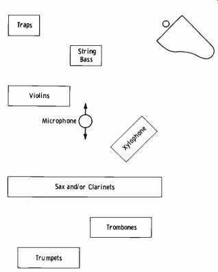
Fig. 11-18. Small-orchestra pickup with bidirectional microphone.
The Symphony
The large symphony orchestra pickup is based on exactly the same principles discussed above. The operator is, however, concerned with a combi nation of each type of orchestral setup into one grouping-strings, wood winds, brasses, percussions, and quite often a choral accompaniment. The grouping of instruments and the type of musical score become much broader in scope. The most helpful characteristic here is the fact that such a program is less apt to be attempted in an inadequately designed studio than are the types of programs discussed previously.
The normal physical arrangement of the orchestra for regular audience listening will generally be satisfactory for broadcast purposes. On the initial trial of the main orchestra microphone, several microphones should be suspended at the most likely pickup positions in order to avoid the con fusion of moving microphones, ladders, and personnel. The general area is 15 to 20 feet high and 15 to 25 feet in front of the violin section.
If a vocalist or instrumental solo is called for, it is almost always necessary to use a second microphone to achieve proper sound perspective. The main orchestra microphone will not act like the human ear. Remember, too, that vocal or instrumental solos are not to be entirely predominant; the orchestral accompaniment must be very much present. Always try, if possible, to get the conductor to listen to the control monitor for a final check on balance. If this is not possible, get some responsible member of the organization to pass on it. The very best control or production men do this simply because every symphony organization has an arrangement of score or possibly a distinct interpretation of the original score with which you cannot be expected to be familiar. This has, many times, necessitated a slight rearrangement of instruments in relation to the microphone.
Along this same line, it has become evident that in spite of the usual superior results obtained with a single well-oriented microphone, it is often necessary to deviate from this practice for true high-fidelity pickup. The main orchestra microphone, back far enough to obtain the proper blend of all instrumental tones, will faithfully pick up the delicate, distant tonal beauty of the violin passages in Clair de Lune. Most music lovers, however, criticize this same microphone setup for such numbers as the Strauss waltzes, where the tonal perspective of the strings should be closer and more strident in quality. It all boils down to the fact that the microphone is not a mechanical extension of the human ear. You will find many leading conductors and producers of symphony broadcasts insisting on an added microphone suspended directly over the strings or other sections of the setup to be turned up only on cue. This procedure supplies the missing psychological factor in obtaining microphone-to-sound perspective. When a choir is used with a symphony orchestra, it is also necessary to use a separate microphone due to the necessary distance between the total combination and the necessary focusing power to be obtained by the use of the microphone. A typical symphony and choir arrangement is shown in Fig. 11-19.
The major difference from the beginning in considering a setup for sym phonies as compared to other broadcasts is the fact that the operator or producer has little to say about the physical arrangement of the orchestra since the interpretation of a score is dependent on the conductor and how he hears the individual and blended tones from the great number of instruments. It will be found in practice that little difference is made in physical arrangement of a large orchestra, since acoustical conditions are usually optimum wherever such organizations perform.
The first information to get when preparing a symphony setup is the program for the broadcast. This should include data on whether or not a choral group is combined with the orchestra and on the types of solos (piano, vocal, etc.) . The next thing to do is to contact the conductor personally (in some cases the symphony business manager must be contacted instead of the conductor) and ascertain if any definite microphone placement is preferred or demanded as dictated by previous experiments or broadcasts. It is then possible to proceed with the preliminary microphone setup as outlined.
In the case of a piano solo with intermittent orchestral accompaniment, no change need be made in the location of the main orchestra microphone, since this nearly always proves ideal for the piano, which is placed in front of the first violin. rows.
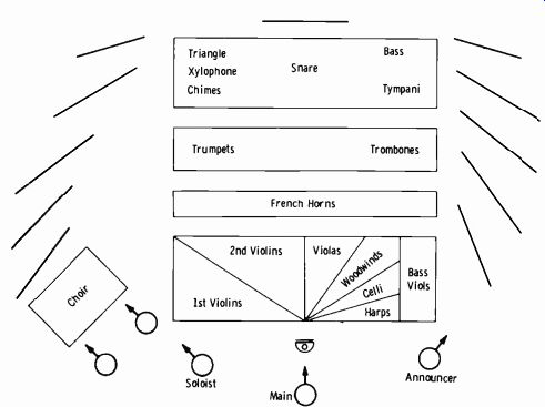
Fig. 11-19. Orchestra and choral arrangement for studio pickup.
Arrangements with a single voice accompaniment almost always require a separate microphone for the vocalist. Remember, however, that this voice must be given auditory presence while the auditory presence of the orchestral accompaniment is maintained.
Remember, too, the listening technique of the symphony listener and that music is the emphasized interest of the program. Announcers should be peaked lower than zero VU by an amount compatible with these conditions. Gain riding is to be held to an absolute minimum; any necessary adjustment of the fader control should be carried out in a gradual, indiscernible manner.
Organ Pickups
Pipe organs are seldom used in studios today, having been largely re placed by the electronic type. In a microphone setup for a pipe organ, sufficient distance must be maintained to get a good blend of tones, and this will naturally be governed by the particular acoustics involved. Cut and try is about the only approach that can be used.
Electronic organs are commonly used in studios. There are two general types of reproducer speakers: the older type with openings on both the sides and top (the major opening is on top), and the newer type that resembles closely the ordinary loudspeaker enclosure with an opening only at the front of the cabinet. Fig. 11-20 illustrates the best arrangements for the two distinct types of reproducers and is self-explanatory.
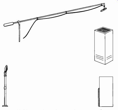
Fig. 11-20. Microphone placement for organ speakers.
Choral Pickups
The wide dynamic range as well as the size of large choral groups emphasize the importance of getting the microphone back as far as the acoustical conditions permit in most ordinary studios. In very large studios, the micro phone should be back far enough that individual voices or sections are not emphasized. It is absolutely essential that risers be used for any large vocal group. When rows of singers are all on the same level, even a microphone raised high by means of a boom stand will not give satisfactory results.
Conventional choir arrangements are often not practical for broadcasting, whether in a regular studio or at a remote point. Fig. 11-21A illustrates the usual arrangement of a choir as used for auditorium or church presentation.
On a broadcast, this arrangement nearly always results in a predominance of soprano voices with very little alto or bass. Fig. 11-21B shows an arrangement much more satisfactory for broadcast purposes, resulting in a better all-around balance of voices.
Importance of Rehearsals
The coordination of hand, ear, sight, and sound for the purpose of blending the component parts of a studio performance is best gained by the operator through rehearsals. Fading in or out of various microphones, turning them off and on, is the procedure which enables the engineer to play on the sound of voice and orchestra much as if the control panel itself were a musical instrument. The ratio of fader adjustments will determine the apparent distance of a singer from the audience; the voice may be smothered with music or may be made to stand alone with only a suggestion of background accompaniment. A proper blend of voice and music, or of dramatics and sound effects, can be created properly only through careful and detailed rehearsals. This is the one and only method of preventing a show from becoming only a caricature of the original idea.
Many experienced operators are familiar with the coloratura soprano who is nicely "adjusted" on rehearsal, then hits +20 VU on the air without batting an eyelash. This condition simply emphasizes one important point:
The operator must be skilled at diplomacy as well as technically conscious.
Talent must be made cognizant of the importance of treating rehearsals just the same as performances. If the performers are instructed in micro phone technique from the point of view of making their performance sound just the way they desire to the listener, the operator will find ready and willing cooperation. Do not be shy of temperament. The more temperamental the performer, the more he likes to be fussed over at rehearsals to gain emphasis of his best talents.
(A) Wrong. (B) Correct.
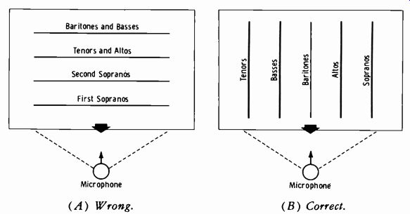
Fig. 11-21. Arrangement for choral pickups.
The distance to be maintained between vocalist and microphone will depend on the type or style of vocal form used by the singer. While the crooner will employ a dynamic range of around 15 VU, the operatic-type singer will use a much wider range. For the former type, it is usually necessary to work close to very close into the microphone. The latter type must be placed a minimum of 4 feet, and preferably 6 to 8 feet, from the micro phone. This may appear to be an excessive distance, but actually a much greater dynamic range and brilliance of voice may be realized by using this distance for singers who produce from extremely low to very high air pressures. There are, of course, a number of in-between singers, such as some of those who sing with dance orchestras, and they are usually placed from 2 to 3 feet from the microphone.
Microphone technique for actors in a dramatic program, or "skits" such as are commonly encountered for various charity fund-raising programs, spells success or failure in creating the desired illusion in the speaker. Usually one microphone is used for the entire cast, with a separate microphone for sound effects. As each actor plays his part, he steps up to the micro phone, sometimes approaching from the fading zone into the announce zone to create the illusion of approaching the scene of action, sometimes leaving in the same manner. In some cases board fades are marked on the script. The operator fades the entire studio setup including sound effects by fading out with the master gain control. Shouts or screams must be per formed in the shading area "off mic" to avoid excessive pressure on the microphone element which would require an excessive gain adjustment by the operator, which would cause loss of the effectiveness of the illusion.
While studio rehearsals are in progress, it is imperative that the engineer and production director be able to talk to the cast for the purpose of instruction in positions, microphone technique, etc. Switches on the control console and perhaps also on the production director's console (where such is used) are provided for the talk-back microphone. The control operator is sometimes provided with a foot switch to free his hands for the controls.
When this microphone is turned on, the control-room speaker is cut off by a relay interlocked with the switch to prevent acoustic feedback. This microphone is also electrically interlocked with the on-air position of the output switch so that it may not be operated during the time a show is actually being broadcast.
11-8. SOUND EFFECTS AND SPECIAL EFFECTS
Sound effects include such things as rainfall, the burning of a building or forest, gunshots, etc. Special effects apply to special handling of a pro gram, such as excessive reverberation to simulate a hall or cavern, or conversely, sound from cramped quarters such as a telephone booth.
Most sound effects are now on disc or tape. However, it sometimes occurs that individually styled sound effects are requested.
In previous years, major network practices in the art of sound effects developed into one of the most highly specialized fields of broadcasting. A sound-effects technician can take the lowly strawberry box and create illusions ranging from the squeak of a wooden gate or the creaks of a ship moored to a dock, to the terrible rending crashes and splintering of wood for collisions of any description. A bow of a bass viol is drawn in a particular manner over the edges of the box for the first effects, and the box is crumbled between the hands close to the microphone for the collision effect. Rainfall is simulated by the pouring of birdseed or buckshot onto a sheet of parchment.
Either a lazy palm-bordered beach or a veritable turmoil of angry waves in an ocean storm can be simulated with BB shot rolled back and forth with skillful timing over a copper screen. Cellophane crackled gently between the hands close to the microphone can create the illusion of the most terrible forest fire imaginable.
The sound technicians' collection includes contrivances such as hail and wind devices, boxes in which glass is shattered, thunder drums, hurricane machines, heavy doors on frames, keys, and a thousand items entirely be yond the scope of this guide to describe. In addition, he has a console on which a number of turntables are mounted with their individual pickup arms and dials which automatically count the number of grooves set in from the edge for proper cueing. These turntables may be varied from 0 to about 150 rpm to make still more flexible the number of effects that can be obtained from recordings.
Ready-made recordings of sound effects are available in thousands of varieties and arrangements. A far from complete outline of general categories follows:
Airplanes: Amphibian, four engine, helicopter, etc.
Animals: Birds, crickets, all types of dogs, fowl, etc.
Automobiles: Ambulance, fire engine, auto in mud, auto with chains, etc.
Crowds: Airport background, applause, cheers, circus, etc.
Industrial: Air hammer, bulldozer, factory whistles, etc.
Marine: Foghorns, motor cruiser, outboard motor, etc.
Trains: Diesel, cable-car, freight, passenger, etc.
War: Air battle, gun shots, explosions, marching, etc.
Weather: Blizzards, rain, thunder, wind, etc.
The voice can be made to sound as though it were coming over a tele phone by means of a filter microphone, which is simply a microphone run through a filter amplifier which clips the high and low frequencies so that the quality is similar to that heard in the telephone receiver. A good tele phone effect can be achieved by feeding a microphone signal through a separate amplifier and exciting a pair of inexpensive headphones held immediately next to another microphone in the studio. Reverberation may be added by feeding the signal into a speaker at one end of a reverberation chamber. The farther away the microphone is placed, the larger becomes the hall or cavern meant to be simulated in the drama. This type of reverberation setup is being largely replaced by a continuous tape arrangement by which any amount of reverberation may be added synthetically to the original sound. The illusion of talking in close quarters, such as in a tele phone booth, is created by placing a microphone in a sound-absorbent booth.
A slight reverberation effect may be obtained by placing a microphone immediately above the sounding board holes of a piano and directing the voice by means of a megaphone or tube over the strings. The sustain pedal is held down to allow the strings to vibrate freely when the voice waves impinge upon them.
Special effects, as distinguished from sound effects, are often called for in modern broadcast programming. Many such effects are achieved by special techniques in disc and tape recording, requiring complex "dubbing" procedures to unify the program.
Perhaps the most common example to illustrate this type of effect is the use of elfin voices and music on certain children's recordings. To get the elfin voice effect, the orchestral background is recorded at 15 inches per second. It is then played back at 7.5 in/s, and the voices of the singers are blended to this tempo on another 7.5-in/s recording. When this recording is played back at 15 in/s, the musical background returns to normal sound, while the voices are stepped up in pitch and tempo.
There are many variations of special recording techniques for special effects. Recording of musical backgrounds and vocal accompaniment on separate tapes allows adding reverberation to either vocal or background at points in the score where this is effective. Reverberation may be added to either one or both simultaneously, or varied at will. Many recordings have made use of such special effects.
11-9. OPERATING THE TURNTABLE AND TAPE EQUIPMENT
Many stations are on almost a complete "disc-jockey" schedule in which the announcer operates the control board, turntables, and tape equipment, in addition to his announcing duties. Fig. 11-22 is a view of the ABC radio studio for disc-jockey-type operation at KQV in Pittsburgh.
The practice of playing recordings and transcriptions varies considerably with different stations. In many stations, the control man operates the turn tables as well as running the control console. In the majority of stations, either the announcer or a specially trained person runs the turntables, which may be in a separate room just for this purpose.
Recorded and transcribed shows constitute a most important part of a broadcaster's daily schedule. Transcriptions are recordings made for broad casting purposes; they usually are 16 inches in diameter, use a turntable speed of 33 1/3 rpm, and are recorded with standard grooves.
Turntables A transcription "platter" may consist of a number of separate musical or voice selections on a single disc, in which case they are numbered on the label with the titles of each number listed. Also on this label will be the information as to type of cut (microgroove or regular) , start on inside or outside groove, and reproduction speed ( 33 1/3, 45, or 78 rpm) . This is enough to keep any operator "on his toes," especially when a program consists of both recordings and transcriptions which may require changing the turntable speed, changing the stylus (1 mil or 3 mil for microgroove or regular) , and noting whether the cut is started on the inside or outside groove.
Courtesy American Broadcasting Co.
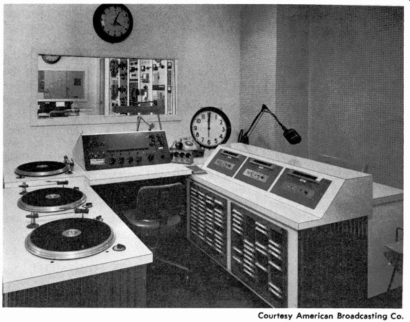
Fig. 11-22. ABC radio studio for disc-jockey operation.
Also, a filter selector switch is employed to select a suitable frequency compensation for the particular disc used. For example, typical switch positions are as follows:
Lateral
1. Transcriptions, Orthacoustic, Columbia
2. Home records and worn transcriptions
3. Home records, World, Decca, and AMP
4. Test records and special recordings ( wide open at highs )
In operating a turntable, it is necessary to be sure that the pickup selector switch is on the proper setting for the pickup arm used, that the turntable speed switch is on the correct speed adjustment for the particular recording used, and that the disc has been properly cued. This means that the pickup stylus must be at the spot on the groove where the announcement or music begins so that no time is lost in waiting for the arm to reach that point on the disc. This is usually accomplished by using headphones or a speaker on an auxiliary amplifier so that each disc may be cued preparatory to going on the air.
When the disc has been properly cued, most experienced operators find it advantageous to start the turntable moving while holding the disc (on the outside edge so as not to touch the grooves) to keep it from turning until start is desired. This practice (called slip cueing) eliminates wow that is likely to occur on starting due to the time taken for the turntable to gain proper running speed. When this trick of operation is not followed, the disc should be cued back at least one full revolution of the turntable so that the proper speed will be reached before the start of the signal. (Some modern turntables require only I/2 revolution to reach proper speed.)
Fig. 11-23 shows the Gates CB-525 turntable. The cartridge may be one of three general types:
1. The turn-around With this type, the knob on the top of the cartridge is depressed and turned so that the desired stylus, 1 mil for microgroove (0.7 mil for stereo) or 2.5 or 3 mils for standard groove, faces the front.
2. The flip-over-The handle at the front of the cartridge is simply turned to the desired position as indicated by the markings on the lever.
3. Some arms employ a complete plug-in head with the desired stylus installed.
Motor On-Off
Frequency Equalizer
Courtesy Gates Division Harris-Intertype Corp.
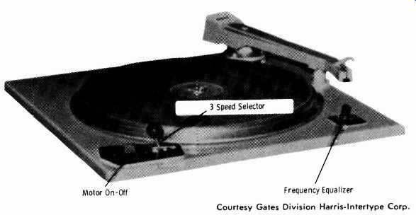
Fig. 11-23. Broadcast transcription turntable.
The music library of a broadcast station may contain files of thousands of recordings and transcriptions, and their proper care in storing and handling is an important factor in on-the-air quality of reproduction. Excessive heat and dust in the air are major enemies to be considered in the storage room.
The library should be well air-conditioned, with an efficient dust-filtering system. In any case, the disc should be cleaned with a soft dry cloth before playing. Static electricity causes dust to cling tightly to records, and all pre cautions such as linoleum floors in the library and turntable room to reduce static electricity should be taken. Finger marks cause noisy reproduction because the oil from the hands causes foreign matter to cling to the walls of the grooves. The discs should be handled by the edges only.
For the same reason, the permanent-type pickup stylus should not be wiped with the fingers in an attempt to clear it of dust. A small soft brush should be used instead.
Magnetic Tape Recording
When recording on magnetic tape, make certain the proper bias is applied to the recording head. This is normally monitored on the same meter used for volume indication by means of a selector switch. Never overload the tape with signal. The program amplitude should not exceed 0 VU or 100 percent (whichever type of scale is used) while recording.
Where short intervals occur between sections of the tape to be edited (portions cut out) , the tape may be pulled by hand over the playback head at approximately the correct speed for intelligibility of the sound. A little practice should develop a fast and sure editing technique. As soon as the last sound of a particular sequence is heard, the tape should be stopped immediately and clipped at the spot where the tape has barely passed the playback head, unless some background sound is present that is desirable to hold a moment or two.
The correct splicing of tape is very important. An angular cut of about 45° should be made, then joined smoothly (do not overlap) with the succeeding portion of tape. Both ends should be cut simultaneously. Use splicing tape only, making sure that the trim is exactly even with the edges of the tape.
When it is known that the tape is to be edited, the technician should observe the following rules.
1. Be very careful of the level fed to the tape during recording. Although modern tape of good quality is hard to overload under usual operating conditions, changes of average level are heavily emphasized upon editing of the tape for playback. Try to avoid unnecessary rerecording for purposes of readjusting respective levels of different portions of the original take.
2. Watch levels of the background noise when tape is to be edited. An originally smooth program can be "choppy" on the air after editing when background music or noise jumps noticeably due to an omitted portion of the tape. Remember that this ratio cannot be readjusted in dubbing.
3. For interviews, try to get some practice takes. The producer will often find these practice sessions more usable than the interview made for the final recording.
4. When musical numbers are to be part of a single show and must originate from different locations under different acoustical conditions, try to avoid even slight amounts of excessive reverberation. The needed reverberation may then be added for the show. This allows control over the separate musical originations, resulting in uniform characteristics. Too much original reverberation cannot be removed.
5. Check the relative microphone distances during all recording to appear on the same program. The reason should be obvious. If the announcer finishes one sentence that was spoken two feet from the microphone and starts the next sentence 6 inches from the micro phone (due perhaps to a time lapse during which the announcer changed position several times, then this portion was edited out) , the listener is apt to get the impression that another person is speaking.
6. Try to educate talent and producers alike that tape recording, especially when editing is required, is a critical technique and should be so handled.
The Automatic Tape Cartridge
Fig. 11-24 illustrates the Fidelipac tape cartridge which is widely used in the broadcast industry. Tape playback speed is normally 7 1/2 inches per second for regular programming. The following operational procedures and drawings are by courtesy of TelePro Industries, Inc., manufacturers of the Fidelipac cartridge, and serve to introduce the reader not familiar with the unit to the proper handling, recording, and playback methods. To visualize the difference between the continuous loop and the mobius loop, study the following two steps:
1. Cut a piece of tape about 1 foot long, and mark one side with a colored crayon. Then turn the tape over and mark the other side with a different colored crayon. To assemble a continuous loop, splice both ends of the same color together forming a loop. Pull the tape between your fingers and observe that no matter how long you keep pulling the tape through your fingers, the same color remains visible at all times. This is termed a continuous loop.
2. Using the same piece of tape, cut the tape at the splice, and re-splice the tape bringing the two different colors together. Again place the tape between your fingers and pull slowly. Note the tape does not turn over or buckle in your hand, but each time you pass the splice, the color changes. This indicates that on one revolution of the tape one side appears, and when the end of the tape is reached at the splice, the other side appears. This is termed a mobius loop.
The tape when threaded on the automatic-tape-cartridge reel is no different than when threaded on a standard reel with the top side removed.
The beginning of the tape is on the hub of the reel, and the end of the tape is on the outside (Fig. 11-25A). To make this reel of tape continuous in operation, simply splice the beginning to the end, forming a continuous loop (Fig. 11-25B) .
Courtesy TelePro Industries, Inc.
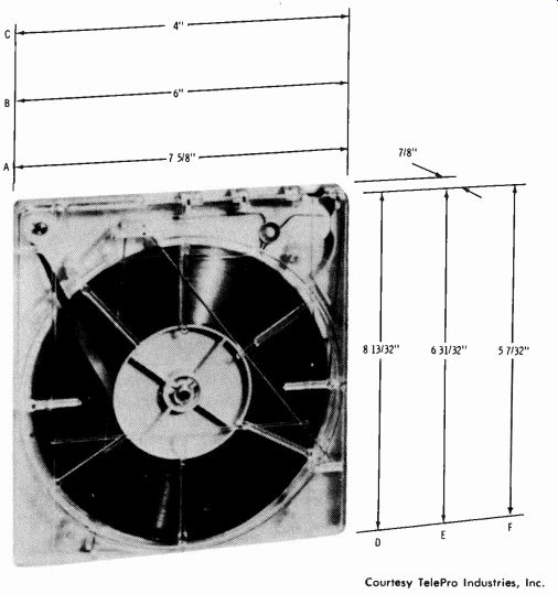
Fig. 11-24. Automatic tape cartridge.
(A) Beginning and end of tape. (B) Tape spliced in continuous loop.
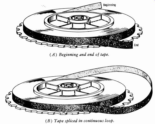
Fig. 11-25. Reell for tape cartridge.
If the reel is placed on a spindle and the tape is pulled from the beginning ( inside) of the reel, the tape rewinds itself on the outside of the reel, and the free loop gets smaller as tape is pulled from the inside. This is due to the fact that the outside diameter of the tape is larger than the diameter at the hub. If this were a normal recording tape, the loop would become so small that it would eventually bind and stop. For this reason, a specially lubricated tape is used to allow the tape to slide on itself at all times. Table 11-2 lists dimensions and recommended loading specifications for these tape cartridges.
NOTE: In the following recording procedures, it is assumed that the recordings are to be made on a conventional tape recorder, then loaded on the automatic tape cartridge. This is conventional practice at many stations where the cartridge machines are playback units only. Some stations also purchase units which are capable of both recording and playback, as described in Section 5-2, Section 5.

Table 11-2. Dimensions and Recommended Loading for Tape Cartridges
------
NOTE: Dimensions are shown in Fig. 11-24; loop lengths are in feet.
Recording Continuous Loop--Place a reel of single-coated tape on the tape recorder, and follow the instructions for recording supplied by the manufacturer of the specific tape recorder used. If you have not used a complete reel of tape to record the information, cut the tape about 1 foot beyond the information recorded. Remove the supply reel. Take the reel from the take-up spindle on the recorder, and, without turning it over, place it on the supply spindle. Place an empty reel on the take-up spindle of the recorder, and wind the recorded tape fast forward in the normal manner. After the tape is completely wound, note that the recorded information now faces away from the recording head.
Place an empty cartridge reel on the supply spindle. Place a metal loading ring over the hub of the cartridge reel, and attach the end of the tape to the loading ring, making sure that the oxide (recorded information) faces outward. By means of fast rewind, wind the recorded information on the cartridge reel. (On the Fidelipac Model 300, simply wind a few turns around the hub; there is no loading ring for this model. The other models can also be loaded in this manner if a loading ring is not available.)

Fig. 11-26. Track positions for mobius-loop operation.
(A) Continuous loop. (B) Mobius loop.
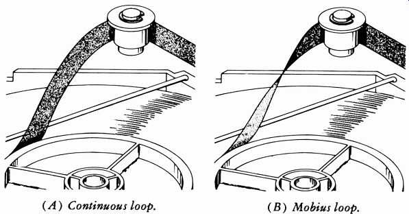
Fig. 11-27. Tape configuration around guide.
Recording Mobius Loop-Place a reel of double-coated tape on the recorder, and record following the normal procedure. After the information has been recorded half-track on one side of the tape, rewind the tape to the supply reel in the normal manner. Take the beginning of the tape, and be fore threading the tape past the head, give it a half-twist. This makes it possible to record on the reverse side, half-track, but not back-to-back with the previous recording. Fig. 11-26 shows the position and the side on which each track has been recorded.
After recording on the reverse side, follow the instructions previously given for rewinding and loading on the magazine reel. When splicing for a mobius loop, care must be taken to twist the tape in the correct direction (Fig. 11-27) .
As the tape comes from the center hub, twist the tape so that it will slope toward the outside of the cartridge as it goes around the corner post. If the tape slopes toward the inside of the cartridge, it is a continuous loop.
The following points apply to any type of recording equipment:
1. The cartridge reel must revolve in a clockwise direction during loading of recorded information.
2. The tape must be loaded with the recorded information facing out ward.
3. The beginning of the program must be at the center of the cartridge reel when starting to load.
4. The tape should be fed to the cartridge reel during loading with as little back tension as possible on the supply reel.
When the tape has been loaded on the cartridge reel, remove the reel from the machine, disengage the tape from the clip on the loading ring (if used), and carefully lift the loading ring off the hub.
Preparing to Splice--Place the loaded reel on a flat surface. Grasp the center of the reel with the right hand to hold it firmly while you pull approximately 18 inches of tape from the outside of the reel. Note that the tape will slip off, so the reel must not be permitted to turn. Remove about 9 inches of tape from the center of the reel by gently pulling on the center end of the tape.
(A) Take up slack. (B) Place tape around guides. Courtesy TelePro Industries, Inc.
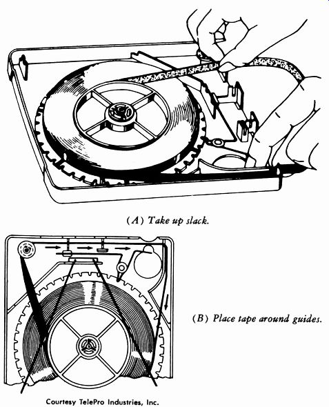
Fig. 11-28. Loading tape cartridge.
Do this carefully so as not to spill the tape from the reel. Make sure there is no twist in either the beginning or end of the tape. For a continuous loop, place the two ends of the tape on the splicer and splice the tape in the normal manner, i.e., oxide to oxide, using Mylar-base splicing tape. (Acetate-base splicing tape generally will break after approximately 100 hours of operation on a fully loaded cartridge.) For a mobius loop, follow the continuous-loop instructions with one exception. Take the beginning of the tape as it comes from the hub, give it one-half twist to the right, and then insert it in the splicer.
Loading the Cartridge--After the tape has been spliced, place the reel in the cartridge with the cartridge front facing forward. With the left hand, release the spring brake over the opening in the bottom left of the cartridge (Fig. 11-28A). This will allow the reel to turn. Pull the tape from the center with the right hand until the slack has been taken up. Place the tape around the guide post, through the front guide slots, and around the left guides as shown in Fig. 11-28B. Again, release the brake and take up all excess slack. Now turn the cartridge so the rear faces you, and pass the long straight wire guide under the tape coming from the center hub; insert the front and rear ends in the holes or slots provided at the front and rear of the cartridge.
On the Fidelipac Model 1200 (large size, now size C) , place the wire with the V on the right side of the reel of tape with the shorter end of the wire guide facing the front of the magazine. The V guide wire should rest near, but not touching the hub, and the V portion of the wire should rest lightly on the tape. This is necessary to keep the tape down against the hub.
The reel must not be raised too high, since this would create excessive down pressure on the tape edge after the lid has been fastened in place.
Before the cartridge is closed, place the cartridge in the tape player with head cover removed, which will allow the lid to be screwed down in place while the reel is in motion. Observe the reel motion carefully to make sure that while the lid is tightened, no binding is produced between the wire guides and the edge of the tape. After complete assembly, if there is too much space between the edge of the tape and the guide wires, remove the reel and add one or more Teflon washers around the center post until the edge of the tape has been raised sufficiently to just touch the wire guides without any pressure being exerted.
On the Fidelipac Model 600 (now Size B) , the guide wire is in a single piece, but the same instructions apply. Only one guide wire is used on the Model 300 (now size A) . Also on this model, use of the loading ring is not necessary. While holding the end of the tape, turn the reel three or four turns so as to give the tape a start; then proceed as instructed previously.
11-10. STEREO SETUPS
The stereo control console provides duplicate channels for feeding two output program lines, for the left and right channels. Any desired number (within design limitations of the console) of microphones may be used for either the left or right channel. An individual VU meter is provided for each channel. It is very important in stereo that the left and right channels be identical in frequency response and phase characteristics.
The console operation for stereo turntable and tape sources is the same as for monaural consoles, except that the disc pickup cartridge and the tape pickup heads each provide two outputs.
In a studio setup for air or recording, at least one microphone each is used for the left and right pickup areas. Directional microphones are normally employed so that each unit picks up first and most strongly the sound for its respective pickup area. When more than one microphone per channel is used, each is directed toward a given area of sound source for its respective (left or right) pickup area.
Important is the fact that no actual "curtain" exists between left and right. A certain amount of opposite-channel sound is picked up, subdued in amplitude and delayed by distance. The result in a properly adjusted receiver is to provide the illusion of dimension or realism found in natural hearing.
The center effect for the two-channel system must be provided by production techniques. With a properly microphoned and balanced production, a given sound source can be made to appear "front and center" even though no speaker exists in the center of the two-channel reproduction.
Loss of this effect is termed a "hole in the center." The term "compatibility," as defined previously, applies only to the technical aspects of broadcasting the sound to the listener, not to pickup technique. The problem of the relationship of background to foreground is the most troublesome aspect. As was emphasized earlier, it is necessary to use the microphone to obtain "attention focusing power" for the listener's mind in a monaural pickup. But in natural hearing, background sounds may be actually quite loud.
To illustrate the problem, consider the example of foreground monologue with musical background. The narrator in this case is at the center, which means the sound is equal in intensity and phase in both the left and right channels. The musical background is dimensioned by conventional stereo pickup. Assume now that a good stereo recording is made so that excellent reproduction results in a stereo system. Assume further that this recording is mixed electronically and presented through a monaural system.
Chances are that the background music will be much too loud. Thus, some compromise is normally made, and this problem will persist until stereo becomes the rule rather than the exception.
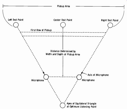
Fig. 11-29. Basic arrangement for stereo pickup.
Fig. 11-29 illustrates the basic rule of thumb for all stereo setups. Draw an equilateral triangle with the apex at the optimum listening point and the base on the first row of the pickup area. Place the two basic pickup microphones with the center axis (of the directional pattern) pointing along the sides of the triangle. The distance will depend on the dimensions of the pickup area, acoustic treatment of studio, and type of presentation, and must be determined by trial. The basic characteristics to be obtained are:
1. A tone sounded at the right test point should result in an output 15 to 20 dB higher from the right microphone than the pickup from the left microphone.
2. A tone sounded at the left test point should result in an output 15 to 20 dB higher from the left microphone than the pickup from the right microphone.
3. A tone sounded from the center test point should result in equal amplitudes from both microphones.
It is sometimes necessary to obtain the center by experimentally moving the source along the base of the triangle until equal amplitudes result. This point may be displaced somewhat from the physical center and is influenced by the acoustics, the number and placement of participants, and the type of program.
Now take a specific example, broadcasting or recording a full orchestra with vocal soloist. Depending on the size of the overall pickup area, the two basic left and right microphones may need to be farther from the soloist than is optimum for good vocal pickup. The soloist may be "lacking in presence" on stereo reproduction, and this will be entirely unacceptable through monophonic systems. A third microphone may be added for the vocalist and bridged into both channels. The following precautions must be observed:
1. If the orchestral sound is too predominant in the center microphone, very little stereo will be evident in the reproduction. Thus the micro phone must be turned off at all times except when required for the soloist.
2. The problem of (1) requires close pickup of the vocalist so that adequate isolation from the orchestra is obtained. (NOTE: This is over come in multiple-track tape master recording by placing the vocalist in an isolated studio with headphones, and recording the solo on a separate track. The proper blend is then made in dubbing onto the stereo tape.)
3. When the soloist must be worked close to the microphone, natural liveness is sacrificed, and artificial reverberation is sometimes used on this one channel only (monophonic) to restore proper sound.
4. When an additional channel is bridged in, it must not introduce phase shift into the other two channels.
The use of artificial reverberation in monaural systems was covered in Section 11-6. It is just as desirable for stereo to correct the actual reverberation time to achieve a value which is suitable for the instruments used or the musical style. But the art of adding artificial reverberation to stereo is not as simple as it might first appear. If, for example, a reverberation device is used in each channel, not only is the phase-frequency problem a severe handicap, but a true "room effect" does not necessarily result.
One type of artificial reverberation unit which has proved satisfactory for both monaural and stereo applications employs a tinned steel plate in the arrangement shown by Fig. 11-30. (NOTE: This description appears here through the courtesy of Electronic Applications, Inc.) While the monaural type is illustrated here, the EMT 140st ( stereo) unit provides an additional pickup to the left of the driver unit; this pickup is identical (in front-view appearance) to that shown on the right in the photo.
Driving Unit Local Reverberation Adjustment Knob
Courtesy EMT
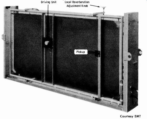
Fig. 11-30. Electromechanical reverberation unit.
The plate, which is excited to transversal vibration, produces numerous reflections of a pulse. These have a linearly increasing repetition rate, which the ear cannot distinguish from a quadratically increasing repetition rate such as occurs in a three-dimensional room. With suitable dimensions and suitable material, the number of natural frequencies is adequate, and the magnitude and the frequency characteristic of the reverberation time are suitable for artificial reverberation. A plate represents the mini mum, but nevertheless adequate, outlay for meeting the requirements of quality for artificial reverberation.
The plate is suspended in its own frame of tubular steel, which is mounted in the angle-iron frame of the outer casing by means of rubber springs. The casing is made of panels of Novopan, a pressed wood-fiber material with plastic binding. A porous damping plate is in a position parallel to the oscillating plate; the spacing between them may be adjusted approximately in the ratio of 1:30. This damping plate is used to vary the reverberation time of the device. The reverberant plate is excited electro-dynamically to transversal vibrations. The vibrations are picked up by means of a piezoelectric contact microphone. The driving unit and the microphone are spot-welded to the steel plate. A power amplifier for the excitation and a voltage amplifier for amplifying the microphone output are contained in a built-in unit. The amplifier chassis is accommodated in one of the narrow sides of the casing, as is the additional remote-control device. By means of this remote control, it is possible to adjust the reverberation time to any desired value from the control desk. An indicating instrument on the control desk shows the reverberation--time setting of the moment. Alternatively, the reverberation time may be adjusted by means of a hand-operated wheel on the upper side of the casing, this wheel being connected with the swinging arms that support the damping plate. The shaft of the hand wheel carries a pointer which shows the reverberation-time setting on a scale on the top of the casing.
Due to the realism of stereophonic sound, special problems involved will become evident from the following review:
The listener will receive the sound from various directions at different intensities and with varying time delay.
1. The direct incidence: The sound waves traveling the shortest possible distance to the listener and which arrive with a minimum of delay.
2. The first reflection: Sound which is reflected from the nearest wall and reaches the listener with very little delay.
3. The second reflection.
4. The successive reflections: The successive reflections consist mostly of sound waves which have been reflected several times before reaching the listener and which are of decreasing intensity. From this it is quite obvious that the succession and intensity with which these re flections occur are strongly influenced by the dimensions of the room and the absorption factor of its boundaries, as well as by the locations of the speaker and the listener. There are many spots in a room at which the intensities of the direct and reflected sound are equal. This area of transition can be geometrically defined as a circle, the center of which is the location from which the sound is being radiated. Out side this imaginary circle, the intensity of the reflected sound predominates. The reflected waves are normally following in rapid succession, and they are decreasing in intensity in such a way that their decay curve can be shown as a function of E (base of natural logarithms).
From this curve the reverberation time can be defined. It is this time which is required for a sound pressure level to decrease 60 dB (a power ratio of one million to one) after the source is turned off.
While it is always possible for the listener to localize the sound source as long as direct radiation dominates, this will become impossible as soon as he finds himself in the reverberant field. Sound is coming at him from every conceivable direction, in many instances diffracted by various elements in the room, and it thus becomes impossible to single out any one directional impression.
From the foregoing it can be concluded that a signal in the reverberant field, while containing the information of the direct sound, will not provide information as to the direction from which it is originating because of the statistical pattern which it follows. An ideal reverberation device for stereo phonic sound should therefore be an apparatus which transmits (without distortion) the information which is contained in the direct sound, but does not distinguish between signals which would contribute to giving a sound source an apparent location when the output of this device is reproduced through a stereophonic system.
The foremost requirement when stereo sound is processed through reverberation devices is to remove from the signal any information which makes it possible to determine the direction of the sound sources, without altering in any way the information which is contained in the program generally (direct sound) . In other words, what is needed is a simple mono phonic signal such as can be had by adding the left and right signals of stereo sound (L-}- R = M) .
The signals are branched off the L and R channels and passed through isolation amplifiers. The amplifier outputs are added to each other, and the resulting sum signal is then fed to the driver system of the reverberation plate. To pick up the signal from the plate, two transmitters (contact microphones) are mounted on it at unequal distances from the driver. The signals delivered by these microphones are therefore not identical to each other, an important requirement for achieving random distribution of the directional information in the reverberated signal which is now to be added to the two stereo channels.
------------------------
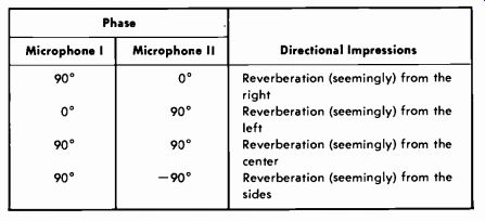
Table
11-3. Reverberation Microphone Phase Relations Phase Directional Impressions
Microphone I Microphone II 90° 0° Reverberation (seemingly) from the right
00 90° Reverberation (seemingly) from the left 90° 90° Reverberation (seemingly)
from the center 90°-90° Reverberation (seemingly) from the sides
--------------------------
A reverberation plate has a very large number of points where resonances occur; in fact there are so many of these resonance points over the whole audio range that we can speak of a resonance spectrum of almost in finite density. This then results in a frequency-dependent phase shift be tween the two transmitters. If the plate is excited with a sinusoidal signal of any frequency, some form of phase relationship will exist between the outputs from the two microphone systems. Of these phase shifts, four are of special interest (Table 11-3).
The directional impressions indicated are those which would be created if two microphones were put in a room to pick up sound from a moving source. It is quite obvious that more than only the four distinct phase relationships will be formed; actually any number of intermediates will occur, and these will depend strongly on frequency. Therefore, if a complex signal such as music or voice is being applied to the plate, all imaginable phase relationships will appear in the outputs of the microphones. Consequently, the reverberated signal will not indicate the original direction of the sound because of the statistical pattern which it follows, thus fulfilling the requirements.
11-11. TRANSMITTER REMOTE-CONTROL OPERATIONS
The majority of AM and fm transmitters are remotely controlled from the studio control room. For a complete visualization of the circuitry involved, the studio operator should be familiar with the calibration and adjustment of such units. The following paragraphs describe the basic adjustment procedure for the Marti RMC-2AXS equipment as utilized with an sd transmitter remote-control system. (Review the description in Section 8-6, Section 8.) Calibration and Adjustment Remote Control Tone Level Adjustment (When Used With STL) The tone-oscillator output levels at the studio unit, RMC-2AXS (Fig. 11-31), are set as follows:
1. With the system operating, hold the telephone dial on the studio-unit panel between any two numbers to key the 20-kHz dial oscillator.
With an ac vtvm or sensitive ac vom, measure the tone-level output at BNC-1 of the studio unit. Set the dial level at 0.5 volt rms with R5. Measure with the unit connected to J1 of STL-8 or across a 560-ohm load resistor.
2. Depress the LOWER lever, and set the 25-kHz lower-oscillator level to 0.5 volt rms with R6.
3. Press the RESET button, and set the 22.5-kHz reset-oscillator level to
0.5 volt rms with R7.
4. Depress the RAISE lever, and set the 27.5-kHz raise-oscillator level to 0.5 volt rms with R8.
5. Reconnect the tone output cable to BNC-1.
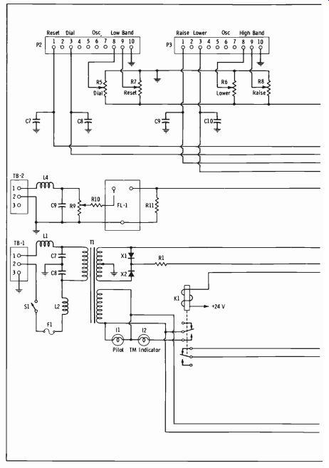
Fig. 11-31. Schematic diagram of RMC-2AXS studio unit.
Fig. 11-32. Partial schematic of RMC-2AXT(A) transmitter unit.
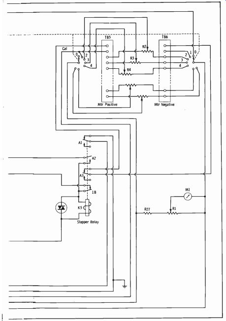
Fig. 11-33. Partial schematic showing relay operations in transmitter unit.
The tone-amplifier levels at the transmitter unit, RMC-2AXT (A) ( Figs. 11-32 and 11-33), are adjusted as follows:
1. With the system operating, hold the dial of the studio unit to key the dial oscillator as in step 1 above. At the transmitter unit, connect a dc meter (0-25 volt scale) with 20,000 ohms per volt sensitivity be tween TP-1 (negative) and the white common jack ( positive) . (See Fig. 11-33.) Set R8 (Fig. 11-32) for a reading of 11 volts dc at TP-1.
2. Depress the LOWER lever at the studio unit, and adjust R9 at the transmitter unit for 11 volts dc at TP-2. (Leave positive meter lead in white jack.)
3. Press the RESET button at the studio unit, and adjust RIO at the transmitter unit for 11 volts dc at TP-3.
4. Depress the RAISE lever at the studio unit, and adjust R11 at the transmitter unit for 11 volts dc at TP-4.
All four remote-control functions should now operate.
Telemeter Tone Modulation Level Adjustment for Telemetering to Studio Over SCA Channel
1. Reset the remote-control system to the off position by pushing the RESET button at the studio.
2. Connect a VU meter across terminals 1 and 3 of TB-3 of the transmitter unit (Fig. 11-32.)
3. Set R12 on the transmitter unit to zero (maximum counterclockwise position.)
4. Feed a 400-Hz tone through the entire SCA system, and set all levels necessary for proper operation at 100-percent modulation of the 67-kHz subcarrier. Record the level of the VU meter at 100-percent SCA modulation.
5. Remove the 400-Hz tone from the SCA-channel input. Dial position 1 on the telephone dial at the studio unit. Set the telemeter tone level with R12 on the transmitter unit for a level 10 VU below the level recorded in step 4 above.
6. With operation as in step 5 above, depress the METER SW on the studio unit, remove the cover knob from the GAIN potentiometer, and with a screwdriver slowly raise the gain control until the meter reaches maximum indication (limiting) . This level should be between 90 and 120 percent on the meter. If this level is not obtained, check the SCA receiver gain setting. Replace the gain cover knob.
7. Release the METER sW and adjust the CALIB knob for Cal (100 percent) on the meter. The system is now calibrated in position 1.
Telemeter Tone Modulation Level Adjustment for Telemetry Over Telephone Line
1. Follow steps 1, 2, and 3 above.
2. Set the telemeter tone level with R12 on the transmitter unit for 2.5 volts rms (+10 VU) at terminals 1 and 3 of TB-3.
3. Follow steps 6 and 7 above.
Calibration of Meter Sample Inputs
1. With the system on calibrate (position 1 of the stepping switch), adjust R1 (meter calibration potentiometer) on the transmitter unit (Fig. 11-33) for Cal on the transmitter-unit meter. (The studio unit should also be reading 100 percent as adjusted in step 7 above.)
2. Dial in the next metering position, and adjust the potentiometer which bears the same number as that position, as indicated by the numbered light, for 100 percent on the meter. (The transmitter being controlled and tele-metered must be operating at exactly 100 percent of normal in all readings.)
3. Repeat step 2 above for all metering positions.
4. Information other than transmitter voltage, current, and power can be tele-metered if desired. Refer to Fig. 11-34A for a method of tele-metering transmitter filament voltage. By means of current transformers, tower-light operation can be tele-metered (Fig. 11-34C).
5. A conversion table ( such as that in Fig. 11-35) must be prepared so that the operator taking a remote reading at the studio can quickly convert the percentage readings from the meter to actual voltage, cur rent, and power values for entry into the station log.
6. For each required measurement, a graph must be prepared and posted at both the transmitter and studio showing the (linear) relationship between actual transmitter meter readings and remote readings.
7. Once weekly, the complete system must be calibrated to meet FCC regulations. (Check current FCC rules.) Electrical-Zero Adjustment of Meter on Studio Unit RMC-2AXS
1. Push the RESET button to turn the system off.
2. Set the mechanical zero-adjustment screw located on the meter front.
3. Dial in a metering position which is not in use.
If all metering positions are used, short-circuit one metering input terminal pair on TB-5 and TB-6 of the transmitter unit to provide a zero-voltage sample into the system.
4. With the system dialed into the zero voltage sample, adjust the trimmer potentiometer on the MC-25 module of the RMC-2AXS studio unit for a zero reading on the studio-unit meter. This trimmer is located on the back of the MC-25 module 3/4 inch from the top edge and %s inch from the left side. Use a small jeweler's screwdriver to punch through the paper label covering the adjustment hole; then make the zero adjustment.
(A) Voltage and current.
(B) R/ power or antenna current.
(C) Tower-light metering.
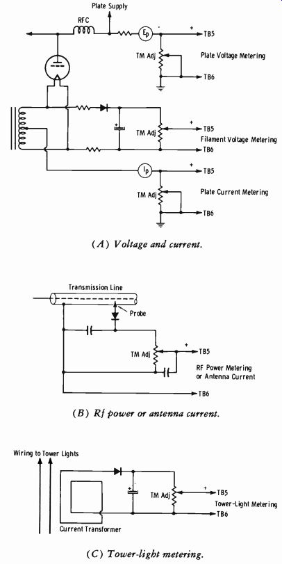
Fig. 11-34. Typical transmitter metering circuits.
Fig. 11-35. Remote control and telemetry operation chart.
Telemetering Linearity Test and Chart
1. Check for mechanical and electrical zero setting of the meter on the studio unit.
2. Turn off the transmitter unit (switch S-1), and set the zero-adjust screw on the meter of this unit.
3. Turn on the transmitter unit, dial position 1 (calibrate), and with potentiometer R1 (Fig. 11-33) set the meter of the transmitter unit to Cal (100 percent). Also adjust the studio-unit CALIB knob until that meter reads " Cal."
4. Connect a 3-volt battery (two flashlight cells in series) to an unused pair of metering terminals on TB-5 and TB-6 of the transmitter unit. Dial in this metering position.
5. Adjust the vernier potentiometer corresponding to the metering terminals to which the battery is connected for a meter reading of 120 percent. The meter on the studio unit should read the same value.
Record the readings at the studio and transmitter units.
6. Repeat the above process in 10-percent steps down to zero percent.
7. On 8" X 10" linear graph paper (10 divisions per inch minimum) , plot a graph of transmitter-unit meter readings versus studio-unit meter readings.
Operation of the RMC-2AX System Control--This system provides remote transmitter off-on control as follows:
1. Turn on all microwave STL and associated studio equipment.
2. On the studio unit, dial the number to which "filaments on" is connected, and operate the RAISE lever to latch the filament-on relay at the transmitter.
3. Next, dial the number for "plates on," and operate the RAISE lever to latch the plate power-supply relay on at the transmitter.
4. To turn the broadcast transmitter off, repeat the above steps, but operate the LOWER lever to turn off the relays at the transmitter.
Measurements and Operating Adjustments
1. To make the required measurements for the log each half hour, first push the RESET button to make sure the stepping relay is in the zero (off) position.
2. Dial 1 on the studio unit, and allow four seconds for the TM (tele meter) light to come on, indicating the system is operating. The meter should now read "Cal," or 100 percent. If not, adjust for 100 percent using the CALIB KNOB. If the meter is not steady, push the METER SW button, and note the telemeter tone level. If it is below about 90 percent, check the SCA fm receiver or make necessary adjustment of the GAIN control.
3. Proceed to dial each meter position, and record each reading in the log using the percentage-to-value conversion table for each reading.
If the meter indicates an adjustment in the transmitter operation is necessary, operate the RAISE or LOWER lever as required until the correct reading is indicated on the meter.
4. When the last reading is dialed in, push RESET. The TM light will go off, and the system will be in standby.
11-12. MEETING EMERGENCIES
In spite of the most thorough maintenance schedules on broadcast equipment, trouble may occur at any time. A well rounded, consistent maintenance schedule will greatly reduce the probability of trouble during the broadcast day. When emergencies do develop, the experience of the opera tor and his familiarity with the equipment will determine the amount of time lost.
To this might be added a third factor-the "human factor." Perhaps this should be classed as a normal subpart of experience, yet many times the supposedly experienced operator will lose as much time under pressure as a comparatively new man. This human factor is the part of being mentally prepared at all times for emergency procedures.
It is obvious that experience and familiarity with specific equipment can not be gained to a great degree by reading this text. Our purpose here is to make suggestions relative to a majority of troubles and illustrate specific examples of applications of emergency procedures. We hope to accomplish this in such a way as to make the reader mentally prepared.
In order that the following discussion be as applicable as possible for the particular type of installation with which the reader is concerned, it is necessary to divide the analysis into two general categories. These are the simple consolette class without associated patch panels, and the more complex installation with means of patching inputs and outputs of the equipment.
Meeting Emergencies Without Patch Panels
Contrary to what the student or new operator might think, the so-called "simple" type of control room, where only a control console is used with out auxiliary amplifiers and patch boards, is the most difficult type to re turn to the air on short notice in case of major trouble. Some consolettes, such as the RCA 76-B5, have a means of switching the entire program circuit to the monitor or spare amplifier, and of feeding this amplifier to the regular program line. This type of installation will be discussed first.
Fig. 11-36 is a simplified block diagram of the 76-B5 consolette. Every operator on the job should be able to draw such a block diagram of his particular installation. We will assume that this equipment is installed as is, without any additional patch panels or auxiliary apparatus, and the micro phones in Studio A are being used. (It makes no difference at present whether the system is on the air or on audition.) One microphone channel goes dead. If this microphone has just been switched on, quickly double check for proper switching positions. If the channel fails while in use, there obviously is trouble.
The first check is to turn on the other microphone, if it is not already.
If this microphone picks up sound, the program channel is operative, and the trouble lies in the microphone, the cable, or the associated preamplifier.
If there is time, check the preamplifier tube, or simply instruct the persons to use the other microphone. If the program is being aired, the other micro phone must be properly placed or the persons must be moved, as quickly as possible.
Suppose, however, that both microphone channels are dead. It is very unlikely that both microphones or cables would be at fault (provided they are plugged in-this illustrates the importance of rehearsals or pre-air microphone checks) . This specific consolette uses a dual power supply; one supply is for the program amplifier and preamplifiers, and one is for the monitor amplifier. It is also unlikely that both preamplifiers would go bad at the same time. Therefore, the most likely points of trouble are the program amplifier (if on the air) or its power supply, or the monitor amplifier (if on audition) .
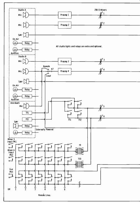
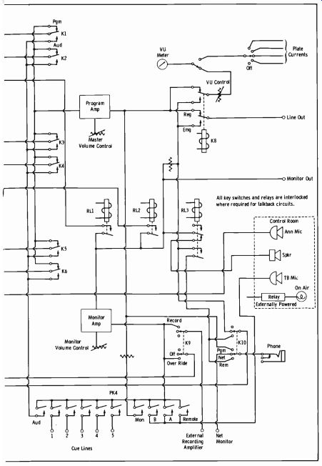
Fig. 11-36. Block diagram of control console.
If the program is being aired, the operator's duty is to get it back on the air in the shortest possible time. The 76-B5 has an emergency provision to supply the preamplifiers with power from the monitor-amplifier power supply by simply throwing a switch on the power-supply panel from the regular to the emergency position. The line out switch may then be thrown from the regular to the emergency position to connect the outgoing line to the monitor amplifier. By throwing the microphone keys to the audition position, the program can then be returned to the air. All operating personnel should be required to practice this procedure before or after broadcast hours when such a setup is provided.
As shown in Fig. 11-36, the turntables (TT1 and TT2) are connected through their respective keys and faders directly to the program amplifier (or monitor amplifier). This is also true of the remote and network lines.
Turntables frequently have preamplifiers of their own installed in the turntable cabinets, and these should not be forgotten in case of a dead turn table. If both pickups are silent, the obvious procedure is to carry out the emergency measures. This bypasses any likely trouble in the power supply or regular program amplifier. Unless the preamplifiers in the turntable are supplied from the regular power supply, the emergency switch on the power supply need not be used, since the preamplifiers within the console are not in use.
In case of failure of an incoming remote or network line, use headphones to monitor the line as it comes in. If the program checks out at the line, it is again obvious that the same emergency procedure is necessary, without the power-supply emergency switching. Know your equipment, and plan every possible emergency check and procedure with the provisions at hand.
This is the art of being mentally prepared. It is also the secret of avoiding panic and confusion, which cut down efficiency in meeting emergencies.
The Consolette
The simplest type of installation ( from an initial cost standpoint) is the single-channel consolette with no emergency provision incorporated in the circuit and no associated patch board or auxiliary equipment. Obviously, emergency procedures may take somewhat longer, but as long as the opera tor meets an emergency with the highest efficiency possible, he is doing his best.
Fig. 11-37 is a block diagram of the Western Electric 23-C consolette when not used with an auxiliary patch panel. Microphone input circuits consist of switching keys K1, K2, K3, K4, and K9, with four single-stage preamplifiers terminating at the mixing potentiometers. Keys K1 through K4 select any of four microphones in either of two studios (up position for one studio, down for the corresponding microphone in the other studio). Key K9 connects an announcing or talk-back microphone in the control room to preamplifier 4 in place of the other microphones. Keys K5 through K8 connect any one of four incoming program lines (or high-level phono pickups or phono preamplifier outputs) to a mixing potentiometer or to the monitor amplifier for preliminary monitoring.
Now consider troubles with this type of installation similar to those discussed previously. Assume a microphone has gone dead. If the others in the studio are still operative, the trouble obviously is in the microphone, cord, or preamplifier associated with that particular channel. If all microphones are dead, there may be more serious trouble.
Naturally, if all the microphones are dead, it is necessary to look to a point common to all microphone channels. Where is the first common point in this example? It is the single-stage, low-level amplifier between the outputs of the microphone mixers and the master gain control. The operator should know where this tube is and be able to change it quickly.
The Western Electric 23-C also has a meter selector switch and associated jack for the purpose of measuring the cathode current of each tube on an external meter. This tube is number 5 on the selector switch. Obviously, if all readings are zero, the trouble is in the power supply, and the 83V rectifier tube should be changed immediately. With consoles such as this that use all glass-type tubes, it is often quicker to lift the top cover and glance at the tubes, looking for a burned-out filament. If the trouble is not in the power supply or the low-level amplifier, it is in the program amplifier, which consists of a 1603 and a 42 output tube.
Assume now that all tubes are good, indicating some trouble in a component part of a circuit common to all microphone channels. Unless the trouble is a complete loss of power due to power-plant failure or a blown fuse on the console ( indicated by all filaments being out) , it is necessary to use the external meter and jack provision to measure all cathode currents.
This generally (not always) provides a quick clue to the faulty stage. If there is simply a short or open in the signal circuit which would not in fluence dc meter readings, further emergency measures to return to the air are called for.
Since we are discussing, at present, the way of efficiently meeting emergencies rather than actual repair of the equipment, we will consider getting back on the air as quickly as possible without completely shutting down and starting a point-to-point service routine. For example, do the turntables feed into a key, K5 to K8, and is this channel operating? Such is possible, since in this specific instance a separate filter section of the common power supply is used to supply the preamplifiers. If trouble (other than a short) should develop here, it is still possible to use sources K5 through K8, since these bypass the preamplifiers. Recordings may then be played until the trouble is cleared or further emergency provisions can be made. If the station is affiliated with a network, the incoming network line may be jumpered to the transmitter line on the line terminal board.
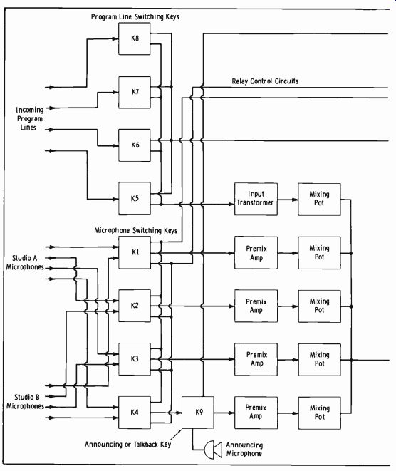
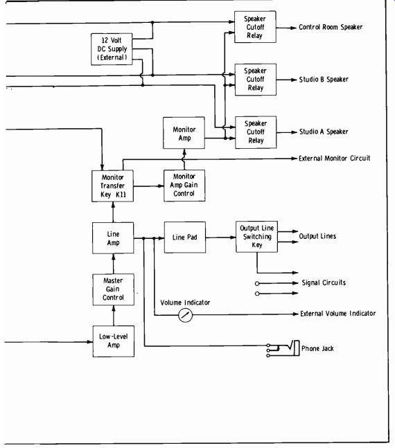
Fig. 11-37. Block diagram of consolette.
If every source available on the consolette is dead and it is apparent that some time will be needed to clear the fault, there is still a last means avail able to nearly all stations to get back on the air quickly, even though under severe limitations. This is by use of a remote amplifier of the type taken to remote points for broadcast purposes. Studio microphones may be connected to this amplifier and the output fed to the transmitter line or to the spare line. Every operator should know where the line terminal board is and have special clip leads available to connect the output of a remote amplifier to the correct line. Certainly every broadcast station, no matter how small and economically limited, should provide this much of an emergency provision.
Patching Around Troubles
Larger studios that have more auxiliary equipment and patching panels are much more efficiently arranged for emergency provisions than those types discussed above. Due to this very complexity, however, such an arrangement is apt to be very confusing, especially to the newcomer. The first rule is to become as familiar as possible with the general type of larger-station setup.
For purposes of discussion, a typical amplifier patch-panel installation may be arranged as follows:
Rack 1: All preamplifiers, low-level amplifiers, and high-level amplifiers used for studio A, with associated jack panel.
Rack 2: Same as rack 1, for studio B.
Rack 3: Same, except associated with transcription and tape sources and announce booth.
Rack 4: All amplifiers and jack panels associated with the master control panel. (Program amplifiers, monitor bus feeds, etc.) Rack 5: Telephone-line terminations for remotes and incoming (and outgoing) network lines.
Fig. 11-38
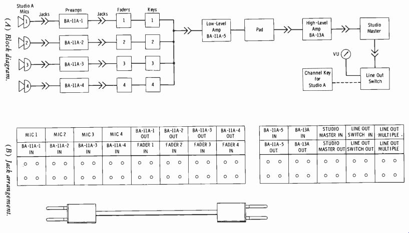
Fig. 11-38 illustrates the complete block diagram of studio A with corresponding
jack-panel designations. Study this illustration closely to become familiar
with the jacks in relation to the signal circuits. Microphone 1, for example,
appears on the upper row of jacks as marked, and the input of BA-11A preamplifier
1 appears on the jacks just below. The following three blocks of jacks duplicate
the same provision for microphones 2, 3, and 4. Then follow the outputs of
preamplifiers 1, 2, 3, and 4, and the in puts to their respective faders.
Then come the jacks associated with the in put and output of the low-level
isolation amplifier (BA-11A number 5), then the high-level amplifier (type
BA-13A), the studio master fader, and the line-out switch connections. In
this installation, the line-out switch may be thrown down for possible feed
to the corresponding studio A key on the master control panel, or it may be
placed in the up position, which connects the studio output to a monitoring
amplifier for audition purposes without tying up one of the three main program
channels. Also in this particular installation, the type BA-11A preamplifiers
numbers 1 through 4, and the isolation amplifier, number 5, obtain their operating
voltages from the high-level amplifier, type BA-13A.
It is obvious that such flexibility is more compatible with emergency measures than the arrangements previously discussed. Assume, for example, that the program stops as indicated by the monitor loudspeaker and the absence of movement of the master control panel VU meter. Since this type of installation uses a separate VU meter on the output of each studio panel, this provides a quick visual check as to whether the main program amplifier is at fault or if the trouble is in the studio circuit. Should the VU indicator of the individual studio still be indicating, it is simply necessary to push the corresponding studio key on channel 2 or channel 3 on the master control panel, and feed the output of this new program channel to the transmitter line. If the studio VU meter is not indicating, the trouble obviously is in the studio high-level amplifier.
Except where the trouble is obvious from the start ( such as when a quick visual examination of the rectifier indicates it to be out), it is advisable to reroute the signal by means of the patch panel. The studio B amplifier rack is an exact replica of the studio A rack and patch panel. If four microphones are used in studio A, it is necessary to patch the output of each microphone into the corresponding preamplifier of studio B. For example, microphone 1 of studio A would be patched to BA-11A-1 IN on the studio B rack, and so on. A patch cord may then be inserted from the studio B STUDIO MASTER OUT jacks to the studio A LINE OUT SWITCH jacks, and the studio B amplifiers are substituted for those of studio A; but now the faders on the studio B operating panel must be used.
It would be possible, of course, simply to patch the microphones of studio A over to the preamplifiers of studio B and then press the studio B key on the master control panel with the line-out switch on studio B down. Note, however, an important complication if this were done. When the line-out switch is in the down ( program) position (as distinguished from up, or audition) and the studio key is pushed on one of the master-control amplifiers, the speaker is cut off in the studio to prevent feedback. If these microphones are patched into another studio and the corresponding key on master control for the substitute studio is pressed, the speaker in that studio will be cut but not the one in the studio where the microphones are. This is apt to cause feedback and result in confusion to the performers as well as the operator. If the operator must use this emergency procedure, he can throw the line-out switch of Studio A to the up (audition) position, which cuts the speaker in Studio A. It is best, however, to return to the studio A position, as in the example given, to avoid confusion in getting out of the emergency operating procedure when the trouble is cleared.
Assume now that only one microphone goes dead. As always, the first thing to do, if only one microphone is being used, is to turn on another microphone in the studio to ascertain if the entire circuit is dead. If only one channel has failed, it is a quick and simple matter to substitute another preamplifier by means of patch cords. For example, if microphone 1 in studio A fails, microphone 1 may be patched to any of the preamplifiers in studio B and from the output of that preamplifier back to FADER 1 IN on the studio-A patch panel. If the microphone is still dead, the operator is faced with a microphone failure and simply must substitute another one.
In patching installations of this type, it is also a simple matter to reroute network or remote signals when trouble develops in the control room. The network or remote line may be patched directly to the transmitter line-in jacks, bypassing all studio equipment.
All of the foregoing simply amounts to this--know the equipment and arrangement; then be mentally prepared.
When the station is affiliated with a network, either high-impedance headphones are provided across the incoming line or a bridging monitor selector switch is used to check network signals before application to the studio amplifiers. As quickly as it is ascertained that the network signal has been lost on the incoming line, the local telephone test board should be contacted. Normally a direct line is provided for this purpose. Trouble is usually quickly located and an alternate path provided by the operating center involved. Fig. 11-39 is a view of the control office for network broad casting in AT&T Long Lines Headquarters, New York City.
Courtesy American Telephone and Telegraph Co.
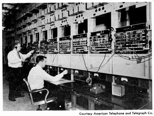
Fig. 11-39. Control office for television and radio networks at the New York
headquarters, Long Lines Dept., American Telephone and Telegraph Co.
11-13. FCC STATEMENT OF POLICY ON "LOUD COMMERCIALS"
The complex subject of 'loudness" was discussed in Section 11-2. Be cause of a consistent barrage of complaints from the general public, the FCC has become involved in arguments between listeners and the broad casting stations particularly as related to loudness of commercials as contrasted to adjacent program material. Although the FCC issued its Statement of Policy Concerning Loud Commercials in July of 1965, few stations have taken any practical steps in attempting a solution to the general problem.
Very recently, the FCC has taken disciplinary action against stations that have a large number of complaints about "loud commercials" filed with the Commission. Due to the extreme importance of the subject, we are presenting below extracts from the FCC report most important to the broadcast operator. In spite of special amplifiers termed "automatic loudness controllers," agc amplifiers, and special metering systems, the problem still exists.
Extracts from FCC Report, Public Notice B, July 12, 1965 By the Commission:
1. During the past two years, the Commission has studied intensively the problem of loud commercials in television and radio. We are told by industry engineers, broadcasters, and others that subjective loudness of commercials cannot be electronically measured, and therefore the Commission cannot act to prevent it. However, in hundreds of complaints from the public we are also told that some commercials are objectionably loud, often louder than adjacent programming-and often so objectionably loud that listeners are compelled to turn the volume down.
2. We conclude today in our Report and Order in the inquiry proceeding (Docket No. 14904) that objectionably loud commercials are a substantial problem, are contrary to the public interest, and that their presentation is to be avoided.
As industry parties point out, there is now no acoustic or electrical tool for determining precisely whether or not a given sound is objectionably loud. Nevertheless, it has been repeatedly held that objectionable or excessive loudness is both a proper subject for preventive government action, and a condition sufficiently definable for its existence to be established for legal purposes.
3. The purpose of this policy statement is threefold--to set forth our policy and the policy we expect licensees to follow in this respect, to detail some of the practices which are common causes of loud commercials, and to advise licensees not knowingly to broadcast commercials involving such practices. All licensees are expected to take appropriate measures to assure strict adherence to this policy. The Commission, through its complaint procedure or by spot checks at renewal time, will determine whether licensees are carrying out their obligations in this respect, and will take whatever action is appropriate on the basis of such review.
4. Among the practices which the Commission has identified as often causing loud commercials, and which licensees shall avoid, are the following:
(1) Excessive modulation on commercials as, for example, through inadequate control-room procedures. We are today amending our modulation rules to make it clear that minimum modulation on peaks of frequent recurrence need not be as much as 85 percent if a lesser level is required to avoid objectionable loudness.
(2) Excessive volume compression resulting from the use of automatic gain control, or similar devices-particularly in the broadcast of pre recorded commercial material which may have been prepared with extensive compression and other electrical processing. Excessive compression permits material to be broadcast at a higher than normal average level of modulation. At least on prerecorded commercial material, a maximum of 6 dB compression in broadcasting is recommended.
(3) Excessive use of other electrical processing devices, such as filters, attenuators, and reverberation units-again, particularly where prerecorded material is being presented.
(4) The use of prerecorded commercials which have been subjected to excessive compression, filtering, attenuation, "equalization," or reverberation (echo) .
(5) Voice commercials presented in a rapid-fire, loud, and strident manner.
(6) The presentation of commercial matter at modulation levels substantially higher than the immediately adjacent programs. A maximum of 4 dB increase (40 percent to 60 percent to 100 percent modulation) is recommended.
To make sure that such practices are avoided, licensees are to adopt adequate control-room procedures to prevent them, and to take appropriate steps to provide for prescreening of recorded commercials for loudness.
5. Much of the loud-commercial problem arises in connection with the broadcast of prerecorded commercials. In fulfilling their obligations in this area, broadcasters are expected to take reasonable steps to get the cooperation of the recording industry so as to prevent the presentation of loud commercials.
6. We now turn to a brief discussion of the matters referred to above.
MINIMUM MODULATION REQUIREMENT
7. One argument advanced by some broadcasters is that they are pre vented by our rules from avoiding loud commercials, because the rules re quire modulation on peaks of frequent recurrence to be at least 85 percent, thus prohibiting the operator from reducing the transmitter gain even if necessary to eliminate loudness. We do not so construe the rules. However, in order to make this matter completely clear, we are today amending the modulation rules to provide that, while in general modulation should not be less than 85 percent on peaks of frequent recurrence, it may be reduced to whatever level is necessary to avoid objectionable loudness in commercial and other material, even if this is substantially less than 85 percent on peaks We expect television and radio broadcasters to observe this practice where necessary to avoid loud commercials.
CONTROL-ROOM PROCEDURES 8. Presentation of loud commercials is due partly to inadequate or lax control-room procedures. One cause is inaccurate reading of or inattention to the modulation monitor (required by our rules) or the widely used volume unit (VU) meter. Another aspect is excessive reliance on automatic gain control (agc) or peak-limiting devices, which, unless properly regulated, are likely to result in loud commercials. Broadcasters are to adopt control-room procedures adequate to prevent the presentation of loud commercials which result from these deficiencies or practices. Attention is invited to a description of accepted procedures in the IRE (now IEEE) Standards on American Practice for Volume Measurement of Electrical Speech and Program Waves, 1953 (53 IRE 3.S2) .
COMPRESSION AND OTHER PROCESSING 9. One contributing cause to the problem of loud commercials is the use of moderate amounts of volume compression, which permits material to be broadcast at a higher than normal average level of modulation without having peaks exceed 100 percent on the modulation meter. Compression in broadcasting, when used in moderation, appears to be desirable; but excessive use thereof, particularly in the broadcast of commercial material, is unquestionably undesirable and a major factor in causing objectionable loudness. Broadcasters are to exercise care in using devices causing compression. It is recommended that an appropriate maximum amount of compression is 6 dB, at least in broadcasting prerecorded commercials. Certainly, as a general rule, no more compression should be used in broadcasting a commercial than in presenting preceding material. Similar care should be used in connection with employment of other processing devices, such as attenuators, filters, or reverberation units. Particular care is to be exercised when the commercial material has been prerecorded, where substantial amounts of compression and other processing may have been used in the recording. The combination of such processing in recording and in broadcasting--e.g., what might be called "compression on compression" may, when carelessly used, produce what one broadcaster has termed "a rather overwhelming effect" in terms of loudness. Therefore, the use of further compression or other electrical processing in broadcasting such commercials is to be avoided to the extent necessary to prevent objection able loudness, and the amount thereof which may properly be used may well be substantially less (e.g., 6 dB of compression less) than that which is appropriate for other types of material.
USE OF RECORDED COMMERCIAL MATERIAL: PRESCREENING 10. Compression, filtering, "equalization," reverberation, and other processing are extensively used in recording commercial material, along with a generally high-volume level of recording. Again, these techniques when used in moderation serve desirable purposes, such as protecting equipment, producing a recording of good technical quality, and producing distinctive effects other than loudness. But it appears that sometimes they are used extensively for no other purpose than to produce loud commercials. Broad casters are to exercise care in the presentation of recorded material in which such processing has been used resulting in an effect of excessive loudness.
Under the revised modulation rules, where a commercial has been pre screened and found too loud, a licensee should reduce modulation below 85 percent where necessary to avoid objectionable loudness. Also as mentioned above, care is to be exercised in the use of any further electrical processing in broadcasting recorded commercial material.
11. We note in "A Guide for Advertising Agencies and Television Stations in Handling Materials for Spot Television Commercials," a joint recommendation of the Station Representatives Association and the American Association of Advertising Agencies, that film, tape, and slides should be in the hands of licensees 48 hours in advance of use. The Guide further suggests that materials should be examined by the station on receipt for "dam age, defects, and completeness." Clearly this contemplates delivery in adequate time to permit prescreening.
12. We are aware that in actual practice these guidelines are not always observed. However, we expect broadcasters to adopt appropriate practices and procedures to provide time for prescreening, not only for damage, completeness, but loudness.
13. We recognize that to require each station, large or small, to pre screen all commercials for loudness may impose some burden. The small radio licensee can engage in extensive spot prescreening, and if a loud commercial escapes prior detection through this process, he can be alert to the need for prescreening further commercials from the same source. Further, we suggest that the organizations, state or national, which represent advertisers, station representatives, agencies and licensees, should consider the establishment of a group to prescreen and label commercial material as to loudness for the industry.
STRIDENT DELIVERY 14. One common source of complaint is commercials which are delivered in a loud, rapid, and strident manner, with the maximum number of words crammed into the time period and all delivered at or close to maxi mum peak modulation. Presentation of such material is to be avoided.
CONTRAST WITH PRECEDING PROGRAM MATERIAL 15. Aside from differences resulting from varying degrees of electrical processing used in different types of material, another common source of complaint is the contrast between loudness of commercials as compared to the volume of preceding program material- e.g., soft music or dialogue immediately followed by a rapid-fire, strident commercial. Such contrasts are to be avoided. For guidance, it is recommended that a maximum of 4 dB increase over the immediately preceding program segment (40 per cent to 60 percent to 100 percent modulation) is appropriate for general observance.
CONCLUSION
16. We conclude that the presentation of objectionably loud commercials is contrary to the public interest. Therefore, to the extent it is within their control, broadcasters have an affirmative obligation to see that such material is not presented. In today's Report and Order we recognize that loudness-the impression created in the listener-is to a degree the result of factors beyond the broadcaster's control and varies as between individual listeners ( for example, a reaction to a particular product or a particular sound effect other than volume) . But we conclude that objectionably loud commercials result in large measure from factors of a technical or partly technical nature which are within the broadcaster's control, and which are not adequately controlled simply by adherence to our rules in the various broadcast services limiting modulation to 100 percent on peaks of frequent recurrence. While there is no evidence that broadcasters in substantial numbers deliberately "boost the power" in presenting commercials, neither is there indication of any concerted, industry-wide effort to deal with the problem. While most complaints of loud commercials are directed to tele vision rather than radio (particularly at prerecorded commercials) , the problem is by no means confined to television.
17. We have set forth above the broadcaster's general affirmative obligation, and specific practices and policies to which we expect strict adherence.
The list of specifics is not intended to be all-inclusive, and there may well be other steps that can be taken. What is called for is a good-faith effort on the part of licensees to prevent the presentation of commercials which are too loud. In setting forth this policy statement, we recognize the under lying importance of advertising to the American system of broadcasting, and the legitimate interest of the advertiser in presenting his message attractively and understandably, and in drawing attention to what he has to say. But these are not irreconcilable alternatives.
18. We note with pleasure a recent suggestion by the American Association of Advertising Agencies that its Subcommittee on Commercial Production might assist in dealing with this problem, by screening commercials referred to it by the Commission about which loudness complaints have been received. We appreciate this offer of assistance, and if the circumstances appear appropriate, we will take advantage of the suggested procedure.
19. We also appreciate the consideration and attention being given this problem by the NAB Engineering Advisory Committee. It is understood that investigations and studies are to be made by this committee, regarding the technical considerations that may be involved in the matter of "loudness," and also as to the possibility of developing a new volume measuring meter. The technical staff of the Commission is, of course, ready to cooper ate in this endeavor as may be requested.
EXERCISES
Q11-1. For the human hearing sense, is a "flat frequency response" desirable all the way from the microphone to the loudspeaker?
Q11-2. What meter other than the VU meter is better in "riding gain" for handling the "loudness factor?"
Q11-3. When a transmitter input gain control has been properly set for 100 percent modulation on program peaks, what will the modulation monitor read on a pure sine-wave tone at 100 percent indication on the studio VU meter?
Q11-4. How many types of artificial-reverberation systems exist?
Q11-5. In Fig. 11-14, if the pianist on the left has a "heavy" left hand (more bass than treble) , what would you do?
Q11-6. What is the basic rule in determining the number of microphones for a given pickup in radio broadcasting?
Q11-7. In the final analysis, who is responsible for public complaints about "loud commercials"?