14. Floppy disks
Floppy disks are the result of a search for a fast yet cheap non-volatile memory for the programmable control store of a processor under development at IBM in the late 1960s. Both magnetic tape and hard disk were ruled out on grounds of cost since only intermittent duty was required. The device designed to fulfill these requirements - the floppy disk drive - incorporated both magnetic-tape and disk technologies.
The floppy concept was so cost-effective that it transcended its original application to become a standard in industry as an online data-storage device. The original floppy disk, or diskette as it is sometimes called, was 8 inches in diameter, but a 5 1/4-inch diameter disk was launched to suit more compact applications. More recently Sony introduced the 3 1/2-inch floppy disk which has a rigid shell with sliding covers over the head access holes to reduce the likelihood of contamination.
Strictly speaking, the floppy is a disk, since it rotates and repeatedly presents the data on any track to the heads, and it has a positioner to give fast two-dimensional access, but it also resembles a tape drive in that the magnetic medium is carried on a flexible substrate which deforms when the read/write head is pressed against it.
Floppy disks are stamped from wide, thick tape, and are anisotropic, because the oxide becomes oriented during manufacture. On many disks this can be seen by the eye as parallel striations on the disk surface. A more serious symptom is the presence of sinusoidal amplitude modulation of the replay signal at twice the rotational frequency of the disk, as illustrated in FIG. 22.
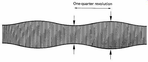
FIG. 22 Sinusoidal amplitude modulation of floppy disk output due
to anisotropy of medium.
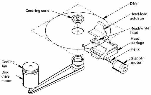
FIG. 23 The mechanism of a floppy disk drive.
Floppy disks have radial apertures in their protective envelopes to allow access by the head. A further aperture allows a photoelectric index sensor to detect a small hole in the disk once per revolution.
FIG. 23 shows that the disk is inserted into the drive edge-first, and slides between an upper and a lower hub assembly. One of these has a fixed bearing which transmits the drive; the other is spring-loaded and mates with the drive hub when the door is closed, causing the disk to be centered and gripped firmly. The moving hub is usually tapered to assist centering. To avoid frictional heating and prolong life, the spindle speed is restricted when compared with that of hard disks. Recent drives almost universally use direct-drive brushless DC motors. Since the rotational latency is so great, there is little point in providing a fast positioner, and the use of leadscrews driven by a stepping motor is universal. The permanent magnets in the stepping motor provide the necessary detenting, and to seek it is only necessary to provide a suitable number of drive pulses to the motor. As the drive is incremental, some form of reference is needed to determine the position of cylinder zero. At the rearward limit of carriage travel, a light beam is interrupted which resets the cylinder count. Upon power-up, the drive has to reverse-seek until this limit is found in order to calibrate the positioner. The grinding noise this makes is a characteristic of most PCs on power-up.
One of the less endearing features of plastics materials is a lack of dimensional stability. Temperature and humidity changes affect plastics much more than metals. The effect on the anisotropic disk substrate is to distort the circular tracks into a shape resembling a dog bone. For this reason, the track width and pitch have to be generous.
The read/write head of a single-sided floppy disk operates on the lower surface only, and is rigidly fixed to the carriage. Contact with the medium is achieved with the help of a spring-loaded pressure pad applied to the top surface of the disk opposite the head. Early drives retracted the pressure pad with a solenoid when not actually transferring data; later drives simply stop the disk. In double-sided drives, the pressure pad is replaced by a second sprung head.
Because of the indifferent stability of the medium, side trim or tunnel erasing is used, because it can withstand considerable misregistration.
FIG. 24 shows the construction of a typical side-trimming head, which has erase poles at each side of the magnetic circuit. When such a head writes, the erase poles are energized, and erase a narrow strip of the disk either side of the new data track. If the recording is made with misregistration, the side-trim prevents traces of the previous recording from being played back as well (FIG. 25).
As the floppy-disk drive was originally intended to be a low-cost item, simple channel codes were used. Early drives used FM and double density drives used MFM, but RLL codes were adopted later to further increase performance. As the recording density becomes higher at the inner tracks, the write current is sometimes programmed to reduce with inward positioner travel.
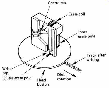
FIG. 24 The poor dimensional stability of the plastic diskette means
that tunnel erase or side trim has to be used. The extra erase poles can
be seen here.
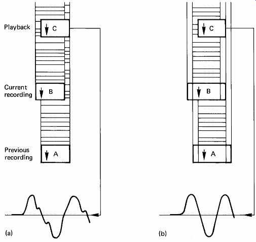
FIG. 25 The effect of side trim is to prevent the traces of a previous
recording from interfering with the latest recording: (a) without side
trim; (b) with side trim.
The capacity of floppy disks is of the order of a few megabytes. This virtually precludes their use for digital audio recording except in conjunction with samplers. However, floppy disks find almost universal application in edit-list storage, console set-up storage, and as a software loading medium for computer-based equipment where the sheer capacity of CDROM is not necessary.
15. Error handling
The protection of data recorded on disks differs considerably from the approach used on other media in digital audio. This has much to do with the traditional intolerance of data processors to errors when compared with audio. In particular, it is not possible to interpolate to conceal errors in a computer program or a data file.
In the same way that magnetic tape is subject to dropouts, magnetic disks suffer from surface defects whose effect is to corrupt data. The shorter wavelengths employed as disk densities increase are affected more by a given size of defect. Attempting to make a perfect disk is subject to a law of diminishing returns, and eventually a state is reached where it becomes more cost-effective to invest in a defect-handling system.
There are four main methods of handling media defects in magnetic media, and further techniques needed in WORM laser disks (see Section 12), whose common goal is to make their presence transparent to the data.
These methods vary in complexity and cost of implementation, and can often be combined in a particular system.
In the construction of bad-block files, a brand new disk is tested by the operating system. Known patterns are written everywhere on the disk, and these are read back and verified. Following this the system gives the disk a volume name, and creates on it a directory structure which keeps records of the position and size of every file subsequently written. The physical disk address of every block which fails to verify is allocated to a file which has an entry in the disk directory. In this way, when genuine data files come to be written, the bad blocks appear to the system to be in use storing a fictitious file, and no attempt will be made to write there.
Some disks have dedicated tracks where defect information can be written during manufacture or by subsequent verification programs, and these permit a speedy construction of the system bad-block file.
In association with the bad-block file, many drives allocate bits in each header to indicate that the associated block is bad. If a data transfer is attempted at such a block, the presence of these bits causes the function to be aborted. The bad-block file system gives very reliable protection against defects, but can result in a lot of disk space being wasted. Systems often use several disk blocks to store convenient units of data called clusters, which will all be written or read together. FIG. 26 shows how a bit map is searched to find free space, and illustrates how the presence of one bad block can write off a whole cluster.
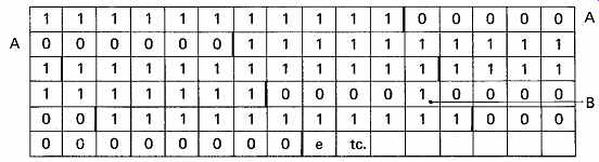
FIG. 26 A disk-block-usage bit map in 16 bit memory for a cluster
size of 11 blocks. Before writing on the disk, the system searches the
bit map for contiguous free space equal to or larger than the cluster size.
The first available space is unusable because the presence of a bad block
B destroys the contiguity of the cluster. Thus one bad block causes the
loss of a cluster.
In sector skipping, space is made at the end of every track for a spare data block, which is not normally accessible to the system. Where a track is found to contain a defect, the affected block becomes a skip sector. In this block, the regular defect flags will be set, but in addition, a bit known as the skip-sector flag is set in this and every subsequent block in the track. When the skip-sector flag is encountered, the effect is to add one to the desired sector address for the rest of the track, as in FIG. 27. In this way the bad block is unused, and the track format following the bad block is effectively slid along by one block to bring into use the spare block at the end of the track. Using this approach, the presence of single bad blocks does not cause the loss of clusters, but requires slightly greater control complexity. If two bad blocks exist in a track, the second will be added to the bad-block file as usual.
The two techniques described so far have treated the block as the smallest element. In practice, the effect of a typical defect is to corrupt only a few bytes. The principle of defect skipping is that media defects can be skipped over within the block so that a block containing a defect is made usable. The header of each block contains the location of the first defect in bytes away from the end of the header, and the number of bytes from the first defect to the second defect, and so on up to the maximum of four shown in the example of FIG. 28. Each defect is overwritten with a fixed number of bytes of preamble code and a sync pattern. The skip is positioned so that there is sufficient undamaged preamble after the defect for the data separator to regain lock. Each defect lengthens the block, causing the format of the track to slip round. A space is left at the end of each track to allow a reasonable number of skips to be accommodated. Often a track descriptor is written at the beginning of each track which contains the physical position of defects relative to index. The disk format needed for a particular system can then be rapidly arrived at by reading the descriptor, and translating the physical defect locations into locations relative to the chosen sector format. FIG. 29 shows how a soft-sectoring drive can have two different formats around the same defects using this principle.
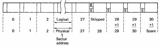
FIG. 27 Skip sectoring. The bad block in this example has a physical
sector address of 28. By setting the skip-sector flags in the header, this
and subsequent logical blocks have one added to their sector addresses,
and the spare block is brought into use.
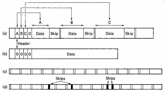
FIG. 28 Defect skipping. (a) A block containing three defects. The
header contains up to four parameters which specify how much data is to
be written before each skip. In this example only three entries are needed.
(b) An error-free block for comparison with (a); the presence of the skips
lengthens the block. To allow for this lengthening, the track contains
spare space at the end, as shown in (c), which is an error-free track.
(d) A track containing the maximum of four skips, which have caused the
spare space to be used up.
FIG. 29 The purpose of the track descriptor record (TDR) is to keep
a record of defects independent of disk format. The positions of the defects
stored in the TDR (a) are used by the formatter to establish the positions
relative to the format used. With the format (b), the first defect appears
in sector 5, but the same defect would be in sector 4 for format (c). The
second defect falls where a header would be written in (b) so the header
is displaced for sector 10. The same defect falls in the data area of sector
8 in (c).
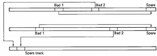
FIG. 30 Revectoring. The first bad block in each track is revectored
to the spare block at the end of the track. Unlike skip sectoring, subsequent
good blocks are unaffected, and the replacement block is read out of sequence.
The second bad block on any one track is revectored to one of a number
of spare tracks kept on the disk for this purpose.
In the case where there are too many defects in a track for the skipping to handle, the system bad-block file will be used. This is rarely necessary in practice, and the disk appears to be contiguous error-free logical and physical space. Defect skipping requires fast processing to deal with events in real time as the disk rotates. Bit-slice microsequencers are one approach, as a typical microprocessor would be too slow.
A refinement of sector skipping which permits the handling of more than one bad block per track without the loss of a cluster is revectoring.
A bad block caused by a surface defect may only have a few defective bytes, so it is possible to record highly redundant information in the bad block. On a revectored disk, a bad block will contain in the data area repeated records pointing to the address where data displaced by the defect can be found. The spare block at the end of the track will be the first such place, and can be read within the same disk revolution, but out of sequence, which puts extra demands on the controller. In the less frequent case of more than one defect in a track, the second and subsequent bad blocks revector to spare blocks available in an area dedicated to that purpose. The principle is illustrated in FIG. 30. In this case a seek will be necessary to locate the replacement block. The low probability of this means that access time is not significantly affected.
These steps are the first line of defense against errors in disk drives, and serve to ensure that, by and large, the errors due to obvious surface defects are eliminated. There are other error mechanisms in action, such as noise and jitter, which can result in random errors, and it is necessary to protect disk data against these also. The error-correction mechanisms described in Section 7 will be employed. In general each data block is made into a codeword by the addition of redundancy at the end. The error-correcting code used in disks was, for a long time, Fire code, because it allowed correction with the minimum circuit complexity. It could, however, only correct one error burst per block, and it had a probability of miscorrection which was marginal for some applications. The advances in complex logic chips meant that the adoption of a Reed-Solomon code was a logical step, since these have the ability to correct multiple error bursts. As the larger burst errors in disk drives are taken care of by verifying the medium, interleaving in the error-correction sense is not generally needed. When interleaving is used in the context of disks, it usually means that the sectors along a track are interleaved so that reading them in numerical order requires two revolutions. This will slow down the data transfer rate where the drive is too fast for the associated circuitry.
In some systems, the occurrence of errors is monitored to see if they are truly random, or if an error persistently occurs in the same physical block.
If this is the case, and the error is small, and well within the correction power of the code, the block will continue in use. If, however, the error is larger than some threshold, the data will be read, corrected and rewritten elsewhere, and the block will then be added to the bad-block file so that it will not be used again.
16. RAID arrays
Whilst the MTBF of a disk drive is very high, it is a simple matter of statistics that when a large number of drives is assembled in a system the time between failures becomes shorter. Winchester drives are sealed units and the disks cannot be removed if there is an electronic failure. Even if this were possible the system cannot usually afford downtime whilst such a data recovery takes place.
Consequently any system in which the data are valuable must take steps to ensure data integrity. This is commonly done using RAID (redundant array of inexpensive disks) technology. FIG. 31 shows that in a RAID array data blocks are spread across a number of drives.
An error-correcting check symbol (typically Reed-Solomon) is stored on a redundant drive. The error correction is powerful enough to fully correct any error in the block due to a single failed drive. In RAID arrays the drives are designed to be hot-plugged (replaced without removing power) so if a drive fails it is simply physically replaced with a new one.
The error-correction system will rewrite the drive with the data which was lost with the failed unit.
When a large number of disk drives are arrayed together, it is necessary and desirable to spread files across all the drives in a RAID array. Whilst this ensures data integrity, it also means that the data transfer rate is multiplied by the number of drives sharing the data. This means that the data transfer rate can be extremely high and new approaches are necessary to move the data in and out of the disk system.
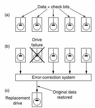
FIG. 31 In RAID technology, data and redundancy are spread over a
number of drives (a). In the case of a drive failure (b) the error-correction
system can correct for the loss and continue operation. When the drive
is replaced (c) the data can be rewritten so that the system can then survive
a further failure.
17. The disk controller
A disk controller is a unit which is interposed between the drives and the rest of the system. It consists of two main parts; that which issues control signals to and obtains status from the drives, and that which handles the data to be stored and retrieved. Both parts are synchronized by the control sequencer. The essentials of a disk controller are determined by the characteristics of drives and the functions needed, and so they do not vary greatly. For digital audio use, it is desirable for economic reasons to use a commercially available disk controller intended for computers. Disk drives are generally built to interface to a standard controller interface, such as the SCSI bus.
The execution of a function by a disk subsystem requires a complex series of steps, and decisions must be made between the steps to decide what the next will be. There is a parallel with computation, where the function is the equivalent of an instruction, and the sequencer steps needed are the equivalent of the microinstructions needed to execute the instruction. The major failing in this analogy is that the sequence in a disk drive must be accurately synchronized to the rotation of the disk.
Most disk controllers use direct memory access, which means that they have the ability to transfer disk data in and out of the associated memory without the assistance of the processor. In order to cause an audio-file transfer, the disk controller must be told the physical disk address (cylinder, sector, track), the physical memory address where the audio file begins, the size of the file and the direction of transfer (read or write). The controller will then position the disk heads, address the memory, and transfer the samples. One disk transfer may consist of many contiguous disk blocks, and the controller will automatically increment the disk address registers as each block is completed. As the disk turns, the sector address increases until the end of the track is reached. The track or head address will then be incremented and the sector address reset so that transfer continues at the beginning of the next track. This process continues until all the heads have been used in turn. In this case both the head address and sector address will be reset, and the cylinder address will be incremented, which causes a seek. A seek which takes place because of a data transfer is called an implied seek, because it is not necessary formally to instruct the system to perform it. As disk drives are block-structured devices, and the error correction is codeword-based, the controller will always complete a block even if the size of the file is less than a whole number of blocks. This is done by packing the last block with zeros.
The status system allows the controller to find out about the operation of the drive, both as a feedback mechanism for the control process and to handle any errors. Upon completion of a function, it is the status system which interrupts the control processor to tell it that another function can be undertaken.
In a system where there are several drives connected to the controller via a common bus, it is possible for non-data-transfer functions such as seeks to take place in some drives simultaneously with a data transfer in another.
Before a data transfer can take place, the selected drive must physically access the desired block, and confirm this by reading the block header.
Following a seek to the required cylinder, the positioner will confirm that the heads are on-track and settled. The desired head will be selected, and then a search for the correct sector begins. This is done by comparing the desired sector with the current sector register, which is typically incremented by dividing down servo-surface pulses. When the two counts are equal, the head is about to enter the desired block. FIG. 32 shows the structure of a typical disk track. In between blocks are placed address marks, which are areas without transitions which the read circuits can detect. Following detection of the address mark, the sequencer is roughly synchronized to begin handling the block. As the block is entered, the data separator locks to the preamble, and in due course the sync pattern will be found. This sets to zero a counter which divides the data-bit rate by eight, allowing the serial recording to be correctly assembled into bytes, and also allowing the sequencer to count the position of the head through the block in order to perform all the necessary steps at the right time.
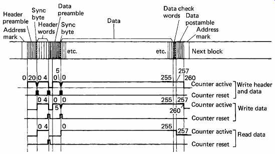
FIG. 32 The format of a typical disk block related to the count process
which is used to establish where in the block the head is at any time.
During a read the count is derived from the actual data read, but during
a write, the count is derived from the write clock.
The first header word is usually the cylinder address, and this is compared with the contents of the desired cylinder register. The second header word will contain the sector and track address of the block, and these will also be compared with the desired addresses. There may also be bad-block flags and/or defect-skipping information. At the end of the header is a CRCC which will be used to ensure that the header was read correctly. FIG. 33 shows a flowchart of the position verification, after which a data transfer can proceed. The header reading is completely automatic. The only time it is necessary formally to command a header to be read is when checking that a disk has been formatted correctly.
During the read of a data block, the sequencer is employed again. The sync pattern at the beginning of the data is detected as before, following which the actual data arrive. These bits are converted to byte or sample parallel, and sent to the memory by DMA. When the sequencer has counted the last data-byte off the track, the redundancy for the error correction system will be following.
During a write function, the header-check function will also take place as it is perhaps even more important not to write in the wrong place on a disk. Once the header has been checked and found to be correct, the write process for the associated data block can begin. The preambles, sync pattern, data block, redundancy and postamble have all to be written contiguously. This is taken care of by the sequencer, which is obtaining timing information from the servo surface to lock the block structure to the angular position of the disk. This should be contrasted with the read function, where the timing comes directly from the data.
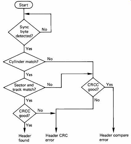
FIG. 33 The vital process of position confirmation is carried out
in accordance with the above flowchart. The appropriate words from the
header are compared in turn with the contents of the disk-address registers
in the subsystem. Only if the correct header has been found and read properly
will the data transfer take place.
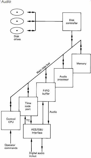
FIG. 34 The main parts of a digital audio disk system. Memory and
FIFO allow continuous audio despite the movement of disk heads between
blocks.
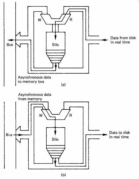
FIG. 35 In order to guarantee that the drive can transfer data in
real time at regular intervals (determined by disk speed and density) the
silo provides buffering to the asynchronous operation of the memory access
process. In (a) the silo is configured for a disk read. The same silo is
used in (b) for a disk write.
18. Digital audio disk systems
In order to use disk drives for the storage of audio samples, a system like the one shown in FIG. 34 is needed. The control computer determines where and when samples will be stored and retrieved, and sends instructions to the disk controller which causes the drives to read or write, and transfers samples between them and the memory. The instantaneous data rate of a typical drive is roughly ten times higher than the sampling rate, and this may result in the system data bus becoming choked by the disk transfers so other transactions are locked out. This is avoided by giving the disk controller DMA system a lower priority for bus access so that other devices can use the bus. A rapidly spinning disk cannot wait, and in order to prevent data loss, a silo or FIFO memory is necessary in the disk controller. 1 The operation of these devices was described in Section 3. A silo will be interposed in the disk controller data stream in the fashion shown in FIG. 35 so that it can buffer data both to and from the disk. When reading the disk, the silo starts empty, the end of the transfer. If this happens some data are lost and the function must be aborted. The block containing the silo overflow will generally be reread on the next revolution. In sophisticated systems, the silo has a kind of dipstick which indicates how far up the V bit is set, and can interrupt the CPU if the data get too deep. The CPU can then suspend some bus activity to allow the disk controller more time to empty the silo.
When the disk is to be written, a continuous data stream must be provided during each block, as the disk cannot stop. The silo will be prefilled before the disk attempts to write as shown in FIG. 36(b), and the disk controller attempts to keep it full. In this case all will be well if the silo does not become empty before the end of the transfer.
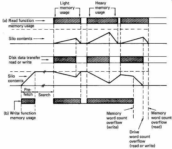
FIG. 36 The silo contents during read functions (a) appear different
from those during write functions (b). In (a), the control logic attempts
to keep the silo as empty as possible; in (b) the logic prefills the silo
and attempts to keep it full until the memory word count overflows.
The disk controller cannot supply samples at a constant rate, because of gaps between blocks, defective blocks and the need to move the heads from one track to another and because of system bus contention.
In order to accept a steady audio sample stream for storage, and to return it in the same way on replay, hard disk-based audio recorders must have a quantity of RAM for buffering. Then there is time for the positioner to move whilst the audio output is supplied from the RAM.
In replay, the drive controller attempts to keep the RAM as full as possible by issuing a read command as soon as one block space appears in the RAM. This allows the maximum time for a seek to take place before reading must resume. FIG. 37 shows the action of the RAM during reading. Whilst recording, the drive controller attempts to keep the RAM as empty as possible by issuing write commands as soon as a block of data is present, as in FIG. 38. In this way the amount of time available to seek is maximized in the presence of a continuous audio sample input.
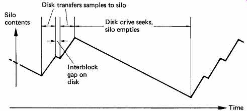
FIG. 37 During an audio replay sequence, silo is constantly emptied
to provide samples, and is refilled in blocks by the drive.
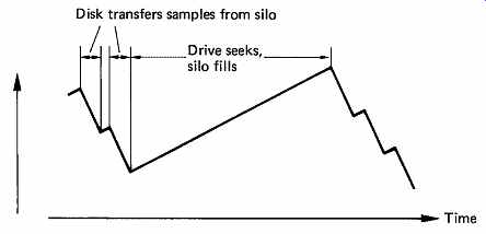
FIG. 38 During audio recording, the input samples constantly fill
the silo, and the drive attempts to keep it empty by reading from it.
19. Arranging the audio data on disk
When playing a tape recording or a disk having a spiral track, it is only necessary to start in the right place and the data are automatically retrieved in the right order. Such media are also driven at a speed which is proportional to the sampling rate. In contrast, a hard disk has a discontinuous recording and acts more like a RAM in that it must be addressed before data can be retrieved. The rotational speed of the disk is constant and not locked to anything. A vital step in converting a disk drive into an audio recorder is to establish a link between the time through the recording and the location of the data on the disk.
When audio samples are fed into a disk-based system, from an AES/ EBU interface or from a convertor, they will be placed initially in RAM, from which the disk controller will read them by DMA. The continuous input sample stream will be split up into disk blocks for disk storage. The AES/EBU interface carries a timecode in the channel status data, and this timecode, or that from a local generator, will be used to assemble a table which contains a conversion from real time in the recording to the physical disk address of the corresponding audio files. As an alternative, an interface may be supplied which allows conventional SMPTE or EBU timecode to be input. Wherever possible, the disk controller will allocate incoming audio samples to contiguous disk addresses, since this eases the conversion from timecode to physical address. [2] This is not, however, always possible in the presence of defective blocks, or if the disk has become chequerboarded from repeated rerecording.
The table of disk addresses will also be made into a named disk file and stored in an index which will be in a different area of the disk from the audio files. Several recordings may be fed into the system in this way, and each will have an entry in the index.
If it is desired to play back one or more of the recordings, then it is only necessary to specify the starting timecode and the filename. The system will look up the index file in order to locate the physical address of the first and subsequent sample blocks in the desired recording, and will begin to read them from disk and write them into the RAM. Once the RAM is full, the real-time replay can begin by sending samples from RAM to the output or to local convertors. The sampling rate clock increments the RAM address and the timecode counter. Whenever a new timecode frame is reached, the corresponding disk address can be obtained from the index table, and the disk drive will read a block in order to keep the RAM topped up.
The disk transfers must by definition take varying times to complete because of the rotational latency of the disk. Once all the sectors on a particular cylinder have been read, it will be necessary to seek to the next cylinder, which will cause a further extension of the reading sequence. If a bad block is encountered, the sequence will be interrupted until it has passed. The RAM buffering is sufficient to absorb all these access time variations. Thus the RAM acts as a delay between the disk transfers and the sound which is heard. A corresponding advance is arranged in timecodes fed to the disk controller. In effect the actual timecode has a constant added to it so that the disk is told to obtain blocks of samples in advance of real time. The disk takes a varying time to obtain the samples, and the RAM then further delays them to the correct timing. Effectively the disk/RAM subsystem is a timecode controlled memory. One need only put in the time and out comes the audio corresponding to that time. This is the characteristic of an audio synchronizer. In most audio equipment the synchronizer is extra; the hard disk needs one to work at all, and so every hard disk comes with a free synchronizer. This makes disk-based systems very flexible as they can be made to lock to almost any reference and care little what sampling rate is used or if it varies. They perform well locked to videotape or film via timecode because no matter how the pictures are shuttled or edited, the timecode link always produces the correct sound to go with the pictures.
A multitrack recording can be stored on a single disk and, for replay, the drive will access the files for each track faster than real time so that they all become present in the memory simultaneously. It is not, however, compulsory to play back the tracks in their original time relationship. For the purpose of synchronization, [3] or other effects, the tracks can be played with any time relationship desired, a feature not possible with multitrack tape drives.
In order to edit the raw audio files fed into the system, it is necessary to listen to them in order to locate the edit points. This can be done by playback of the whole file at normal speed if time is no object, but this neglects the random access capability of a disk-based system. If an event list has been made at the time of the recordings, it can be used to access any part of them within a few tens of milliseconds, which is the time taken for the heads to traverse the entire disk surface. This is far superior to the slow spooling speed of tape recorders.
20. Spooling files
If an event list is not available, it will be necessary to run through the recording at a raised speed in order rapidly to locate the area of the desired edit. If the disk can access fast enough, an increase of up to ten times normal speed can be achieved simply by raising the sampling-rate clock, so that the timecode advances more rapidly, and new data blocks are requested from the disk more rapidly. If a constant sampling-rate output is needed, then rate reduction via a digital filter will be necessary. [4,5] Some systems have sophisticated signal processors which allow pitch changing, so that files can be played at non-standard speed but with normal pitch or vice versa. [6]
If higher speeds are required, an alternative approach to processing on playback only is to record spooling files [7] at the same time as an audio file is made. A spooling file block contains a sampling-rate-reduced version of several contiguous audio blocks. When played at standard sampling rate, it will sound as if it is playing faster by the factor of rate reduction employed. The spooling files can be accessed less often for a given playback speed, or higher speed is possible within a given access-rate constraint.
Once the rough area of the edit has been located by spooling, the audio files from that area can be played to locate the edit point more accurately.
It is often not sufficiently accurate to mark edit points on the fly by listening to the sound at normal speed. In order to simulate the rock-and roll action of edit-point location in an analog tape recorder, audio blocks in the area of the edit point can be transferred to memory and accessed at variable speed and in either direction by deriving the memory addresses from a hand-turned rotor. A description of this process is included in the next section where digital audio editing is discussed.
21. Broadcast applications
In a radio broadcast environment it is possible to contain all the commercials and jingles in daily use on a disk system thus eliminating the doubtful quality of analog cartridge machines. [8] Disk files can be cued almost instantly by specifying the file name of the wanted piece, and once RAM resident play instantly they are required. Adding extra output modules means that several audio files can be played back simultaneously if a station broadcasts on more than one channel. If a commercial break contains several different spots, these can be chosen at short notice just by producing a new edit list.
22. Sampling rate and playing time
The bit rate of a digital audio system is such that high-density recording is mandatory for long playing time. A disk drive can never reach the density of a rotary-head tape machine because it is optimized for fast random access, but the performance of all types of data recorders has advanced so rapidly that disk drive capacity is no longer an issue in digital audio applications.
One high-quality digital audio channel requires nearly a megabit per second, which means that a gigabyte of storage (the usual unit for disk measurement) offers about three hours of monophonic audio. There is, however, no compulsion to devote the whole disk to one audio channel, and so in one gigabyte of storage, two channels could be recorded for 90min, or four channels for 45min and so on. For broadcast applications, where an audio bandwidth of 15 kHz is imposed by the FM stereo transmission standard, the alternative sampling rate of 32 kHz can be used, which allows about four hours of monophonic digital audio per gigabyte. Where only speech is required, an even lower rate can be employed. Compression can also be used to obtain greater playing time, but with the penalty of loss of quality.
In practice, multitrack working with disks is better than these calculations would indicate, because on a typical multitrack master tape, all tracks are not recorded continuously. Some tracks will contain only short recordings in a much longer overall session. A tape machine has no option but to leave these tracks unrecorded either side of the wanted recording, whereas a disk system will only store the actual wanted samples. The playing time in a real application will thus be greater than expected.
A further consideration is that hard disks systems do not need to edit the actual data files on disk. The editing is performed in the memory of the control system and is repeated dynamically under the control of an EDL (edit decision list) each time the edited work is required. Thus a lengthy editing session on a hard disk system does not result in the disk becoming fuller as only a few bytes of EDL are generated.
References
1. Ingbretsen, R.B. and Stockham, T.G., Random access editing of digital audio. J. Audio Eng. Soc., 32, 114-122 (1982)
2. McNally, G.W., Gaskell, P.S. and Stirling, A.J., Digital audio editing. BBC Research Dept Report, RD 1985/10
3. McNally, G.W., Bloom, P.J. and Rose, N.J., A digital signal processing system for automatic dialogue post-synchronization. Presented at the 82nd Audio Engineering Society Convention ( London, 1987), Preprint 2476(K-6)
4. McNally, G.W., Varispeed replay of digital audio with constant output sampling rate. Presented at the 76th Audio Engineering Society Convention (New York, 1984), Preprint 2137(A-9)
5. Gaskell, P.S., A hybrid approach to the variable speed replay of audio. Presented at the 77th Audio Engineering Society Convention ( Hamburg, 1985), Preprint 2202(B-1)
6. Gray, E., The Synclavier digital audio system: recent developments in audio post production. Int. Broadcast Eng., 18, 55 (March 1987)
7. McNally, G.W., Fast edit-point location and cueing in disk-based digital audio editing. Presented at the 78th Audio Engineering Society Convention ( Anaheim, 1985), Preprint 2232(D-10)
8. Itoh, T., Ohta, T. and Sohma, Y., Real time transmission system of commercial messages in radio broadcasting. Presented at the 67th Audio Engineering Society Convention (New York, 1980), Preprint 1682(H-1)