<< cont. from part 1
17. Networks
In the most general sense a network is means of communication between a large number of places. According to this definition the Post Office is a network, as are parcel and courier companies. This type of network delivers physical objects. If, however, we restrict the delivery to information only the result is a telecommunications network. The telephone system is a good example of a telecommunications network because it displays most of the characteristics of later networks.
It is fundamental in a network that any port can communicate with any other port. FIG. 24 shows a primitive three-port network. Clearly each port must select one or other of the remaining ports in a trivial switching system. However, if it were attempted to redraw FIG. 24 with one hundred ports, each one would need a 99-way switch and the number of wires needed would be phenomenal. Another approach is needed.
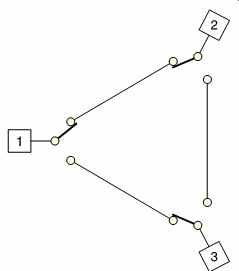
FIG. 24 Switching is simple with a small number of ports.
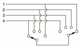
FIG. 25 An exchange or switch can connect any input to any output,
but extra switching is needed to support more than one connection.
FIG. 25 shows that the common solution is to have an exchange, also known as a router, hub or switch, which is connected to every port by a single cable. In this case when a port wishes to communicate with another, it instructs the switch to make the connection. The complexity of the switch varies with its performance. The minimal case may be to install a single input selector and a single output selector. This allows any port to communicate with any other, but only one at a time. If more simultaneous communications are needed, further switching is needed.
The extreme case is where every possible pair of ports can communicate simultaneously.
The amount of switching logic needed to implement the extreme case is phenomenal and in practice it is unlikely to be needed. One fundamental property of networks is that they are seldom implemented with the extreme case supported. There will be an economic decision made balancing the number of simultaneous communications with the equipment cost. Most of the time the user will be unaware that this limit exists, until there is a statistically abnormal condition which causes more than the usual number of nodes to attempt communication.
The phrase 'the switchboard was jammed' has passed into the language and stayed there despite the fact that manual switchboards are only seen in museums. This is a characteristic of networks. They generally only work up to a certain throughput and then there are problems. This doesn't mean that networks aren't useful, far from it. What it means is that with care, networks can be very useful, but without care they can be a nightmare.
There are two key factors to get right in a network. The first is that it must have enough throughput, bandwidth or connectivity to handle the anticipated usage and the second is that a priority system or algorithm is chosen which has appropriate behavior during overload. These two characteristics are quite different, but often come as a pair in a network corresponding to a particular standard.
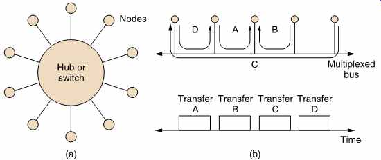
FIG. 26 (a) Radial installations need a lot of cabling. Time-division
multiplexing, where transfers occur during different time frames, reduces
this requirement (b).
Where each device is individually cabled, the result is a radial network shown in FIG. 26(a). It is not necessary to have one cable per device and several devices can co-exist on a single cable if some form of multiplexing is used. This might be time-division multiplexing (TDM) or frequency division multiplexing (FDM). In TDM, shown in FIG. 26(b), the time axis is divided into steps which may or may not be equal in length. In Ethernet, for example, these are called frames. During each time step or frame a pair of nodes have exclusive use of the cable. At the end of the time step another pair of nodes can communicate. Rapidly switching between steps gives the illusion of simultaneous transfer between several pairs of nodes. In FDM, simultaneous transfer is possible because each message occupies a different band of frequencies in the cable. Each node has to 'tune' to the correct signal. In practice it is possible to combine FDM and TDM. Each frequency band can be time multiplexed in some applications.
Data networks originated to serve the requirements of computers and it is a simple fact that most computer processes don't need to be performed in real time or indeed at a particular time at all. Networks tend to reflect that background as many of them, particularly the older ones, are asynchronous.
Asynchronous means that the time taken to deliver a given quantity of data is unknown. A TDM system may chop the data into several different transfers and each transfer may experience delay according to what other transfers the system is engaged in. Ethernet and most storage system buses are asynchronous. For broadcasting purposes an asynchronous delivery system is no use at all, but for copying a video data file between two storage devices an asynchronous system is perfectly adequate.
The opposite extreme is the synchronous system in which the network can guarantee a constant delivery rate and a fixed and minor delay. An AES/EBU router is a synchronous network.
In between asynchronous and synchronous networks reside the isochronous approaches. These can be thought of as sloppy synchronous networks or more rigidly controlled asynchronous networks. Both descriptions are valid. In the isochronous network there will be maximum delivery time which is not normally exceeded. The data transmission rate may vary, but if the rate has been low for any reason, it will accelerate to prevent the maximum delay being reached. Isochronous networks can deliver near-real-time performance. If a data buffer is provided at both ends, synchronous data such as AES/EBU audio can be fed through an isochronous network. The magnitude of the maximum delay determines the size of the buffer and the length of the fixed overall delay through the system. This delay is responsible for the term 'near-real time'. ATM is an isochronous network.
These three different approaches are needed for economic reasons.
Asynchronous systems are very efficient because as soon as one transfer completes, another can begin. This can only be achieved by making every device wait with its data in a buffer so that transfer can start immediately.
Asynchronous systems also make it possible for low bit rate devices to share a network with high bit rate devices. The low bit rate device will only need a small buffer and will therefore send short data blocks, whereas the high bit rate device will send long blocks. Asynchronous systems have no difficulty in handling blocks of varying size, whereas in a synchronous system this is very difficult.
Isochronous systems try to give the best of both worlds, generally by sacrificing some flexibility in block size. FireWire is an example of a network which is part isochronous and part asynchronous so that the advantages of both are available.
18. Introduction to NICAM 728
This system was developed by the BBC to allow the two additional high quality digital sound channels to be carried on terrestrial television broadcasts. Performance was such that the system was adopted as the UK standard, and was recommended by the EBU to be adopted by its members, many of whom put it into service. [24]
The introduction of stereo sound with television cannot be at the expense of incompatibility with the existing monophonic analog sound channel. In NICAM 728 an additional low-power subcarrier is positioned just above the analog sound carrier, which is retained. The relationship is shown in FIG. 27. The power of the digital subcarrier is about one hundredth that of the main vision carrier, and so existing monophonic receivers will reject it.
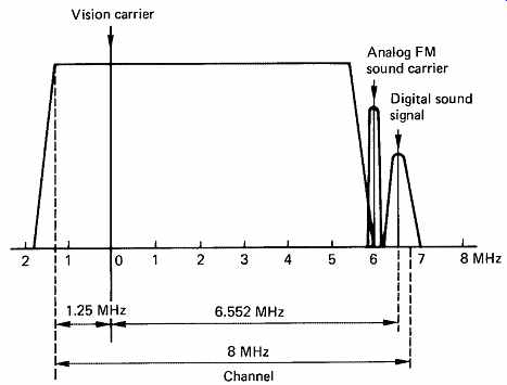
FIG. 27 The additional carrier needed for digital stereo sound is
squeezed in between television channels as shown here. The digital carrier
is of much lower power than the analog signals, and is randomized prior
to transmission so that it has a broad, low-level spectrum which is less
visible on the picture.
Since the digital carrier is effectively shoe-horned into the gap between TV channels, it is necessary to ensure that the spectral width of the intruder is minimized to prevent interference. As a further measure, the power of the existing audio carrier is halved when the digital carrier is present.
FIG. 28 shows the stages through which the audio must pass. The audio sampling rate used is 32 kHz which offers similar bandwidth to that of an FM stereo radio broadcast. Samples are originally quantized to fourteen-bit resolution in two's complement code. From an analog source this causes no problem, but from a professional digital source having longer wordlength and higher sampling rate it would be necessary to pass through a rate convertor, a digital equalizer to provide pre emphasis, an optional digital compressor in the case of wide dynamic range signals and then through a truncation circuit incorporating digital dither as explained in Section 4.
The fourteen-bit samples are block companded to reduce data rate.
During each one millisecond block, 32 samples are input from each audio channel. The magnitude of the largest sample in each channel is independently assessed, and used to determine the gain range or scale factor to be used. Every sample in each channel in a given block will then be scaled by the same amount and truncated to ten bits. An eleventh bit present on each sample combines the scale factor of the channel with parity bits for error detection. The encoding process is described as a Near Instantaneously Companded Audio Multiplex, NICAM for short.
The resultant data now consists of 2 x 32 x 11 = 704 bits per block. Bit interleaving is employed to reduce the effect of burst errors.
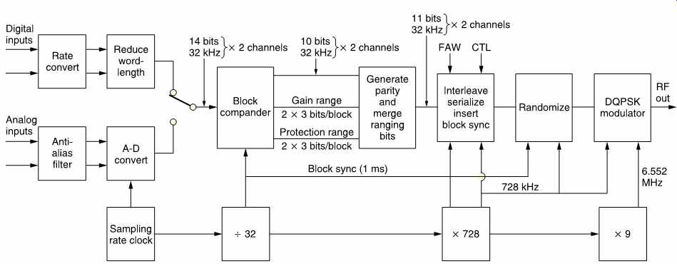
FIG. 28 The stage necessary to generate the digital subcarrier in
NICAM 728. Audio samples are block companded to reduce the bandwidth needed.
At the beginning of each block a synchronizing byte, known as a Frame Alignment Word, is followed by five control bits and eleven additional data bits, making a total of 728 bits per frame, hence the number in the system name. As there are 1000 frames per second, the bit rate is 728 kbits/s. In the UK this is multiplied by 9 to obtain the digital carrier frequency of 6.552MHz but some other countries use a different subcarrier spacing.
The digital carrier is phase modulated. It has four states which are 90° apart. Information is carried in the magnitude of a phase change which takes place every 18 cycles, or 2.74 us. As there are four possible phase changes, two bits are conveyed in every change. The absolute phase has no meaning, only the changes are interpreted by the receiver. This type of modulation is known as differentially encoded quadrature phase shift keying (DQPSK), sometimes called four-phase DPSK. In order to provide consistent timing and to spread the carrier energy throughout the band irrespective of audio content, randomizing is used, except during the frame alignment word. On reception, the FAW is detected and used to synchronize the pseudo-random generator to restore the original data.
FIG. 29 shows the general structure of a frame. Following the sync pattern or FAW is the application control field. The application control bits determine the significance of following data, which can be stereo audio, two independent mono signals, mono audio and data or data only.
Control bits C1, C2 and C3 have eight combinations, of which only four are currently standardized. Receivers are designed to mute audio if C3 becomes 1.
The frame flag bit C0 spends eight frames high then eight frames low in an endless sixteen-frame sequence which is used to synchronize changes in channel usage. In the last sixteen-frame sequence of the old application, the application control bits change to herald the new application, whereas the actual data change to the new application on the next sixteen frame sequence.
The reserve sound switching flag, C4, is set to 1 if the analog sound being broadcast is derived from the digital stereo. This fact can be stored by the receiver and used to initiate automatic switching to analog sound in the case of loss of the digital channels.
The additional data bits AD0 to AD10 are as yet undefined, and reserved for future applications.
The remaining 704 bits in each frame may be either audio samples or data. The two channels of stereo audio are multiplexed into each frame, but multiplexing does not occur in any other case. If two mono audio channels are sent, they occupy alternate frames. FIG. 29(a) shows a stereo frame, where the A channel is carried in odd-numbered samples, whereas FIG. 29(b) shows a mono frame, where the M1 channel is carried in odd numbered frames. The format for data has yet to be defined.

FIG. 29 In (a) the block structure of a stereo signal multiplexes
samples from both channels (A and B) into one block.
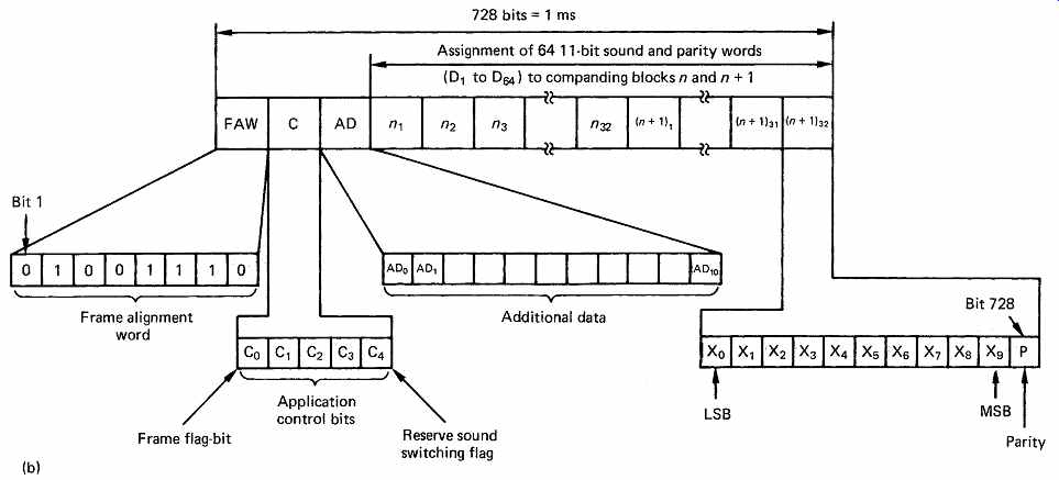
FIG. 29 In mono, shown in (b), samples from one channel only occupy
a given block. The diagrams here show the data before interleaving. Adjacent
bits shown here actually appear at least sixteen bits apart in the data
stream.
The sound/data block of NICAM 728 is in fact identical in structure to the first-level protected companded sound signal block of the MAC/ packet systems. [25]
19. Audio in digital television broadcasting
Digital television broadcasting relies on the combination of a number of fundamental technologies. These are: MPEG-2 compression to reduce the bit rate, multiplexing to combine picture and sound data into a common bitstream, digital modulation schemes to reduce the RF bandwidth needed by a given bit rate and error correction to reduce the error statistics of the channel down to a value acceptable to MPEG data.
MPEG compressed video and audio are both highly sensitive to bit errors, primarily because they confuse the recognition of variable-length codes so that the decoder loses synchronization. However, MPEG is a compression and multiplexing standard and does not specify how error correction should be performed. Consequently a transmission standard must define a system which has to correct essentially all errors such that the delivery mechanism is transparent.
Essentially a transmission standard specifies all the additional steps needed to deliver an MPEG transport stream from one place to another.
This transport stream will consist of a number of elementary streams of video and audio, where the audio may be coded according to MPEG audio standard or AC-3. In a system working within its capabilities, the picture and sound quality will be determined only by the performance of the compression system and not by the RF transmission channel. This is the fundamental difference between analog and digital broadcasting. In analog television broadcasting, the picture quality may be limited by composite video encoding artifacts as well as transmission artifacts such as noise and ghosting. In digital television broadcasting the picture quality is determined instead by the compression artifacts and interlace artifacts if interlace has been retained.
If the received error rate increases for any reason, once the correcting power is used up, the system will degrade rapidly as uncorrected errors enter the MPEG decoder. In practice decoders will be programmed to recognize the condition and blank or mute to avoid outputting garbage.
As a result, digital receivers tend either to work well or not at all.
It is important to realize that the signal strength in a digital system does not translate directly to picture quality. A poor signal will increase the number of bit errors. Provided that this is within the capability of the error-correction system, there is no visible loss of quality. In contrast, a very powerful signal may be unusable because of similarly powerful reflections due to multipath propagation.
Whilst in one sense an MPEG transport stream is only data, it differs from generic data in that it must be presented to the viewer at a particular rate. Generic data are usually asynchronous, whereas baseband video and audio are synchronous. However, after compression and multiplexing audio and video are no longer precisely synchronous and so the term isochronous is used. This means a signal which was at one time synchronous and will be displayed synchronously, but which uses buffering at transmitter and receiver to accommodate moderate timing errors in the transmission.
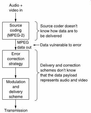
FIG. 30 Source coder doesn't know delivery mechanism and delivery
mechanism doesn't need to know what the data mean.
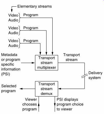
FIG. 31 Program Specific Information helps the demultiplexer to select
the required program.
Clearly another mechanism is needed so that the time axis of the original signal can be recreated on reception. The time stamp and program clock reference system of MPEG does this.
FIG. 30 shows that the concepts involved in digital television broadcasting exist at various levels which have an independence not found in analog technology. In a given configuration a transmitter can radiate a given payload data bit rate. This represents the useful bit rate and does not include the necessary overheads needed by error correction, multiplexing or synchronizing. It is fundamental that the transmission system does not care what this payload bit rate is used for. The entire capacity may be used up by one high-definition channel, or a large number of heavily compressed channels may be carried. The details of this data usage are the domain of the transport stream. The multiplexing of transport streams is defined by the MPEG standards, but these do not define any error correction or transmission technique.
At the lowest level in FIG. 31 the source coding scheme, in this case MPEG compression, results in one or more elementary streams, each of which carries a video or audio channel. Elementary streams are multiplexed into a transport stream. The viewer then selects the desired elementary stream from the transport stream. Metadata in the transport stream ensures that when a video elementary stream is chosen, the appropriate audio elementary stream will automatically be selected.
20. Packets and time stamps
The video elementary stream is an endless bitstream representing pictures which take a variable length of time to transmit. Bi-direction coding means that pictures are not necessarily in the correct order. Storage and transmission systems prefer discrete blocks of data and so elementary streams are packetized to form a PES (packetized elementary stream).
Audio elementary streams are also packetized. A packet is shown in FIG. 32. It begins with a header containing an unique packet start code and a code which identifies the type of data stream. Optionally the packet header also may contain one or more time stamps which are used for synchronizing the video decoder to real time and for obtaining lip-sync.
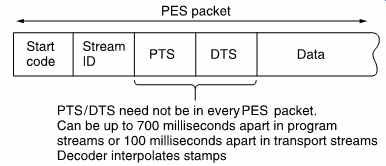
FIG. 32 A PES packet structure is used to break up the continuous
elementary stream.

FIG. 33 Time stamps are the result of sampling a counter driven by
the encoder clock.
FIG. 33 shows that a time stamp is a sample of the state of a counter which is driven by a 90 kHz clock. This is obtained by dividing down the master 27MHz clock of MPEG-2. This 27MHz clock must be locked to the video frame rate and the audio sampling rate of the program concerned.
There are two types of time stamp: PTS and DTS. These are abbreviations for presentation time stamp and decode time stamp. A presentation time stamp determines when the associated picture should be displayed on the screen, whereas a decode time stamp determines when it should be decoded. In bidirectional coding these times can be quite different.
Audio packets only have presentation time stamps. Clearly if lip-sync is to be obtained, the audio sampling rate of a given program must have been locked to the same master 27MHz clock as the video and the time stamps must have come from the same counter driven by that clock.
In practice the time between input pictures is constant and so there is a certain amount of redundancy in the time stamps. Consequently PTS/ DTS need not appear in every PES packet. Time stamps can be up to 100ms apart in transport streams. As each picture type (I, P or B) is flagged in the bitstream, the decoder can infer the PTS/DTS for every picture from the ones actually transmitted.
21. MPEG transport streams
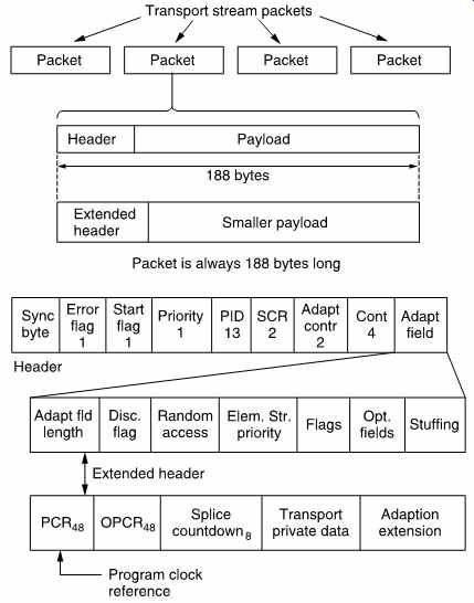
FIG. 34 Transport stream packets are always 188 bytes long to facilitate
multiplexing and error correction.
The MPEG-2 transport stream is intended to be a multiplex of many TV programs with their associated sound and data channels, although a single program transport stream (SPTS) is possible. The transport stream is based upon packets of constant size so that multiplexing, adding error correction codes and interleaving in a higher layer is eased. FIG. 34 shows that these are always 188 bytes long.
Transport stream packets always begin with a header. The remainder of the packet carries data known as the payload. For efficiency, the normal header is relatively small, but for special purposes the header may be extended. In this case the payload gets smaller so that the overall size of the packet is unchanged. Transport stream packets should not be confused with PES packets which are larger and which vary in size. PES packets are broken up to form the payload of the transport stream packets.
The header begins with a sync byte which is an unique pattern detected by a demultiplexer. A transport stream may contain many different elementary streams and these are identified by giving each an unique thirteen-bit packet identification code or PID which is included in the header. A multiplexer seeking a particular elementary stream simply checks the PID of every packet and accepts only those which match.
In a multiplex there may be many packets from other programs in between packets of a given PID. To help the demultiplexer, the packet header contains a continuity count. This is a four-bit value which increments at each new packet having a given PID.
This approach allows statistical multiplexing as it does not matter how many or how few packets have a given PID; the demux will still find them. Statistical multiplexing has the problem that it is virtually impossible to make the sum of the input bit rates constant. Instead the multiplexer aims to make the average data bit rate slightly less than the maximum and the overall bit rate is kept constant by adding 'stuffing' or null packets. These packets have no meaning, but simply keep the bit rate constant. Null packets always have a PID of 8191 (all ones) and the demultiplexer discards them.
22. Clock references
A transport stream is a multiplex of several TV programs and these may have originated from widely different locations. It is impractical to expect all the programs in a transport stream to be genlocked and so the stream is designed from the outset to allow unlocked programs. A decoder running from a transport stream has to genlock to the encoder and the transport stream has to have a mechanism to allow this to be done independently for each program. The synchronizing mechanism is called program clock reference (PCR).
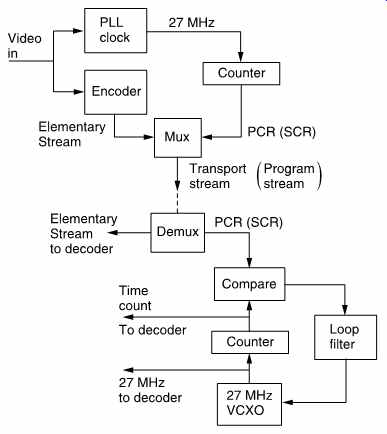
FIG. 35 Program or System Clock Reference codes regenerate a clock
at the decoder.
FIG. 35 shows how the PCR system works. The goal is to re-create at the decoder a 27MHz clock which is synchronous with that at the encoder. The encoder clock drives a 48-bit counter which continuously counts up to the maximum value before overflowing and beginning again.
A transport stream multiplexer will periodically sample the counter and place the state of the count in an extended packet header as a PCR (see FIG. 34). The demultiplexer selects only the PIDs of the required program, and it will extract the PCRs from the packets in which they were inserted.
The PCR codes are used to control a numerically locked loop (NLL) described in section 3.16. The NLL contains a 27MHz VCXO (voltage controlled crystal oscillator). This is a variable-frequency oscillator based on a crystal which has a relatively small frequency range.
The VCXO drives a 48-bit counter in the same way as in the encoder.
The state of the counter is compared with the contents of the PCR and the difference is used to modify the VCXO frequency. When the loop reaches lock, the decoder counter would arrive at the same value as is contained in the PCR and no change in the VCXO would then occur. In practice the transport stream packets will suffer from transmission jitter and this will create phase noise in the loop. This is removed by the loop filter so that the VCXO effectively averages a large number of phase errors.
A heavily damped loop will reject jitter well, but will take a long time to lock. Lock-up time can be reduced when switching to a new program if the decoder counter is jammed to the value of the first PCR received in the new program. The loop filter may also have its time constants shortened during lock-up.
Once a synchronous 27MHz clock is available at the decoder, this can be divided down to provide the 90 kHz clock which drives the time stamp mechanism.
The entire timebase stability of the decoder is no better than the stability of the clock derived from PCR. MPEG-2 sets standards for the maximum amount of jitter which can be present in PCRs in a real transport stream.
Clearly if the 27MHz clock in the receiver is locked to one encoder it can only receive elementary streams encoded with that clock. If it is attempted to decode, for example, an audio stream generated from a different clock, the result will be periodic buffer overflows or underflows in the decoder. Thus MPEG defines a program in a manner which relates to timing. A program is a set of elementary streams which have been encoded with the same master clock.
23. Program Specific Information (PSI)
In a real transport stream, each elementary stream has a different PID, but the demultiplexer has to be told what these PIDs are and what audio belongs with what video before it can operate. This is the function of PSI which is a form of metadata. FIG. 36 shows the structure of PSI. When a decoder powers up, it knows nothing about the incoming transport stream except that it must search for all packets with a PID of zero. PID zero is reserved for the Program Association Table (PAT). The PAT is transmitted at regular intervals and contains a list of all the programs in this transport stream. Each program is further described by its own Program Map Table (PMT) and the PIDs of the PMTs are contained in the PAT.
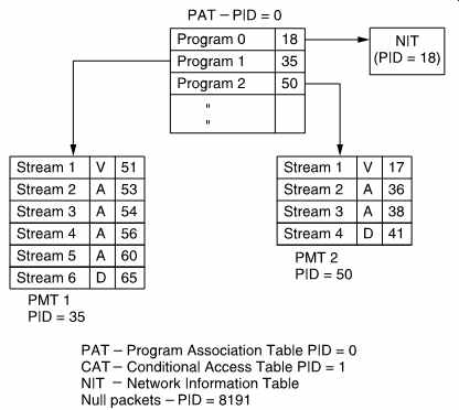
FIG. 36 MPEG-2 Program Specific Information (PSI) is used to tell
a demultiplexer what the transport stream contains.
FIG. 36 also shows that the PMTs fully describe each program. The PID of the video elementary stream is defined, along with the PID(s) of the associated audio and data streams. Consequently when the viewer selects a particular program, the demultiplexer looks up the program number in the PAT, finds the right PMT and reads the audio, video and data PIDs. It then selects elementary streams having these PIDs from the transport stream and routes them to the decoders.
Program 0 of the PAT contains the PID of the Network Information Table (NIT). This contains information about what other transport streams are available. For example, in the case of a satellite broadcast, the NIT would detail the orbital position, the polarization, carrier frequency and modulation scheme. Using the NIT a set-top box could automatically switch between transport streams.
Apart from 0 and 8191, a PID of 1 is also reserved for the Conditional Access Table (CAT). This is part of the access control mechanism needed to support pay per view or subscription viewing.
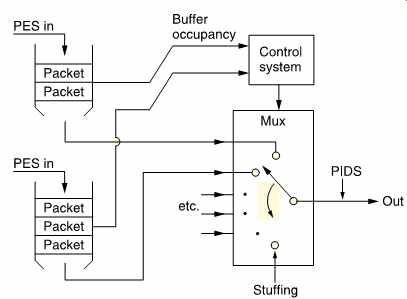
FIG. 37 A transport stream multiplexer can handle several programs
which are asynchronous to one another and to the transport stream clock.
See text for details.
24. Multiplexing
A transport stream multiplexer is a complex device because of the number of functions it must perform. A fixed multiplexer will be considered first. In a fixed multiplexer, the bit rate of each of the programs must be specified so that the sum does not exceed the payload bit rate of the transport stream. The payload bit rate is the overall bit rate less the packet headers and PSI rate.
In practice the programs will not be synchronous to one another, but the transport stream must produce a constant packet rate given by the bit rate divided by 188 bytes, the packet length. FIG. 37 shows how this is handled. Each elementary stream entering the multiplexer passes through a buffer which is divided into payload-sized areas. Note that periodically the payload area is made smaller because of the requirement to insert PCR.
MPEG-2 decoders also have a quantity of buffer memory. The challenge to the multiplexer is to take packets from each program in such a way that neither its own buffers nor the buffers in any decoder either overflow or underflow. This requirement is met by sending packets from all programs as evenly as possible rather than bunching together a lot of packets from one program. When the bit rates of the programs are different, the only way this can be handled is to use the buffer contents indicators. The fuller a buffer is, the more likely it should be that a packet will be read from it. Thus a buffer content arbitrator can decide which program should have a packet allocated next.
If the sum of the input bit rates is correct, the buffers should all slowly empty because the overall input bit rate has to be less than the payload bit rate. This allows for the insertion of Program Specific Information. Whilst PATs and PMTs are being transmitted, the program buffers will fill up again. The multiplexer can also fill the buffers by sending more PCRs as this reduces the payload of each packet. In the event that the multiplexer has sent enough of everything but still can't fill a packet then it will send a null packet with a PID of 8191. Decoders will discard null packets and as they convey no useful data, the multiplexer buffers will all fill whilst null packets are being transmitted.
The use of null packets means that the bit rates of the elementary streams do not need to be synchronous with one another or with the transport stream bit rate. As each elementary stream can have its own PCR, it is not necessary for the different programs in a transport stream to be genlocked to one another; in fact they don't even need to have the same frame rate.
This approach allows the transport stream bit rate to be accurately defined and independent of the timing of the data carried. This is important because the transport stream bit rate determines the spectrum of the transmitter and this must not vary.
In a statistical multiplexer or statmux, the bit rate allocated to each program can vary dynamically. FIG. 38 shows that there must be tight connection between the statmux and the associated compressors. Each compressor has a buffer memory which is emptied by a demand clock from the statmux. In a normal, fixed bit rate, coder the buffer content feeds back and controls the requantizer. In statmuxing this process is less severe and only takes place if the buffer is very close to full, because the degree of coding difficulty is also fed to the statmux.
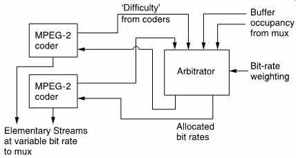
FIG. 38 A statistical multiplexer contains an arbitrator which allocates
bit rate to each program as a function of program difficulty.
The statmux contains an arbitrator which allocates more packets to the program with the greatest coding difficulty. Thus if a particular program encounters difficult material it will produce large prediction errors and begin to fill its output buffer. As the statmux has allocated more packets to that program, more data will be read out of that buffer, preventing overflow. Of course this is only possible if the other programs in the transport stream are handling typical video.
In the event that several programs encounter difficult material at once, clearly the buffer contents will rise and the requantizing mechanism will have to operate.
25. Introduction to DAB
Until the advent of NICAM and MAC, all sound broadcasting had been analog. The AM system is now very old indeed, and is not high fidelity by any standards, having a restricted bandwidth and suffering from noise, particularly at night. In theory, the FM system allows high quality and stereo, but in practice things are not so good. Most FM broadcast networks were planned when a radio set was a sizeable unit which usually needed an antenna for AM reception. Signal strengths were based on the assumption that a fixed FM antenna in an elevated position would be used. If such an antenna is used, reception quality is generally excellent. The forward gain of a directional antenna raises the signal above the front-end noise of the receiver and noise-free stereo is obtained.
Such an antenna also rejects unwanted signal reflections.
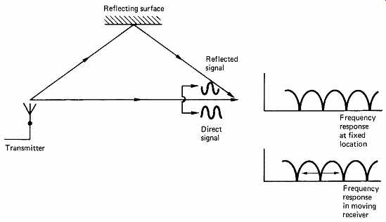
FIG. 39 Multipath reception. When the direct and reflected signals
are received with equal strength, nulling occurs at any frequency where
the path difference results in a 180° phase shift.
Unfortunately, most FM receivers today are portable radios with whip antennae which have to be carefully oriented to give best reception. It is a characteristic of FM that slight mistuning causes gross distortion so an FM set is harder to tune than an AM set. In many places, nationally broadcast channels can be received on several adjacent frequencies at different strengths. Non-technical listeners tend to find all of this too much and surveys reveal that AM listening is still commonplace despite the same program being available on FM.
Reception on car radios is at a greater disadvantage as directional antennae cannot be used. This makes reception prone to multipath problems. FIG. 39 shows that when the direct and reflected signals are received with equal strength, nulling occurs at any frequency where the path difference results in a 180° phase shift. Effectively a comb filter is placed in series with the signal. In a moving vehicle, the path lengths change, and the comb response slides up and down the band. When a null passes through the station tuned in, a burst of noise is created.
Reflections from aircraft can cause the same problem in fixed receivers.
Digital audio broadcasting (DAB), also known as digital radio, is designed to overcome the problems which beset FM radio, particularly in vehicles. Not only does it do that, it does so using less bandwidth. With increasing pressure for spectrum allocation from other services, a system using less bandwidth to give better quality is likely to be favorably received.
26 DAB principles
DAB relies on a number of fundamental technologies which are combined into an elegant system. Compression is employed to cut the required bandwidth. Transmission of digital data is inherently robust as the receiver has only to decide between a small number of possible states. Sophisticated modulation techniques help to eliminate multipath reception problems whilst further economizing on bandwidth. Error correction and concealment allow residual data corruption to be handled before conversion to analog at the receiver.
The system can only be realized with extremely complex logic in both transmitter and receiver, but with modern VLSI technology this can be inexpensive and reliable. In DAB, the concept of one-carrier-one-program is not used. Several programs share the same band of frequencies.
Receivers will be easier to use since conventional tuning will be unnecessary. 'Tuning' consists of controlling the decoding process to select the desired program. Mobile receivers will automatically switch between transmitters as a journey proceeds.
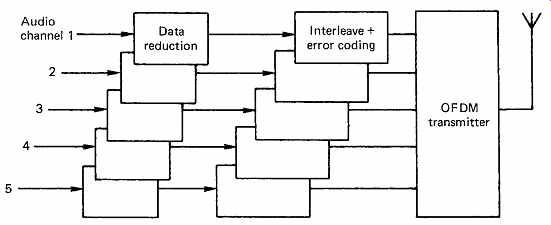
FIG. 40 Block diagram of a DAB transmitter. See text for details.
FIG. 40 shows the block diagram of a DAB transmitter. Incoming digital audio at 32 kHz is passed into the compression unit which uses the techniques described in Section 5 to cut the data rate to some fraction of the original. The compression unit could be at the studio end of the line to cut the cost of the link. The data for each channel are then protected against errors by the addition of redundancy. Convolutional codes described in Section 7 are attractive in the broadcast environment.
Several such data-reduced sources are interleaved together and fed to the modulator, which may employ techniques such as randomizing which were introduced in Section 6.
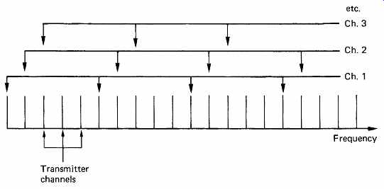
FIG. 41 Channel interleaving is used in DAB to reduce the effect of
multipath notches on a given program.
FIG. 41 shows how the multiple carriers in a DAB band are allocated to different program channels on an interleaved basis. Using this technique, it will be evident that when a notch in the received spectrum occurs due to multipath cancellation this will damage a small proportion of all programs rather than a large part of one program. This is the spectral equivalent of physical interleaving on a recording medium.
The result is the same in that error bursts are broken up according to the interleave structure into more manageable sizes which can be corrected with less redundancy.
A serial digital waveform has a sinx/x spectrum and when this waveform is used to phase modulate a carrier the result is a symmetrical sinx/x spectrum centered on the carrier frequency. Nulls in the spectrum appear at multiples of the phase switching rate away from the carrier.
This distance is equal to 90° or one quadrant of sinx. Further carriers can be placed at spacings such that each is centered at the nulls of the others.
Owing to the quadrant spacing, these carries are mutually orthogonal, hence the term orthogonal frequency division. [26, 27]
A number of such carriers will interleave to produce an overall spectrum which is almost rectangular as shown in FIG. 42(a). The mathematics describing this process is exactly the same as that of the reconstruction of samples in a low-pass filter and reference should be made to Figure 4.6. Effectively sampling theory has been transformed into the frequency domain.
In practice, perfect spectral interleaving does not give sufficient immunity from multipath reception. In the time domain, a typical reflective environment turns a transmitted pulse into a pulse train extending over several microseconds. [28]
If the bit rate is too high, the reflections from a given bit coincide with later bits, destroying the orthogonality between carriers. Reflections are opposed by the use of guard intervals in which the phase of the carrier returns to an unmodulated state for a period which is greater than the period of the reflections. Then the reflections from one transmitted phase decay during the guard interval before the next phase is transmitted. [29]
The principle is not dissimilar to the technique of spacing transitions in a recording further apart than the expected jitter. As expected, the use of guard intervals reduces the bit rate of the carrier because for some of the time it is radiating carrier not data. A typical reduction is to around 80 percent of the capacity without guard intervals. This capacity reduction does, however, improve the error statistics dramatically, such that much less redundancy is required in the error correction system. Thus the effective transmission rate is improved. The use of guard intervals also moves more energy from the sidebands back to the carrier. The frequency spectrum of a set of carriers is no longer perfectly flat but contains a small peak at the center of each carrier as shown in FIG. 42(b).
A DAB receiver must receive the set of carriers corresponding to the required program channel. Owing to the close spacing of carriers, it can only do this by performing fast Fourier transforms (FFTs) on the DAB band. If the carriers of a given program are evenly spaced, a partial FFT can be used which only detects energy at spaced frequencies and requires much less computation. This is the DAB equivalent of tuning. The selected carriers are then demodulated and combined into a single bit stream. The error-correction codes will then be de-interleaved so that correction is possible. Corrected data then pass through the expansion part of the data reduction coder, resulting in conventional PCM audio which drives DACs.
It should be noted that in the European DVB standard, COFDM transmission is also used. In some respects, DAB is simply a form of DVB without the picture data.

FIG. 42 (a) When mutually orthogonal carriers are stacked in a band,
the resultant spectrum is virtually flat. (b) When guard intervals are
used, the spectrum contains a peak at each channel center.
References
1. Audio Engineering Society, AES recommended practice for digital audio engineering - serial transmission format for linearly represented digital audio data. J. Audio Eng. Soc., 33, 975-984 (1985)
2. EIAJ CP-340, a Digital Audio Interface, Tokyo: EIAJ (1987)
3. EIAJ CP-1201, Digital Audio Interface (revised), Tokyo: EIAJ (1992)
4. IEC 958, Digital Audio Interface, 1st edn, Geneva: IEC (1989)
5. Finger, R., AES3-1992: the revised two channel digital audio interface. J. Audio. Eng. Soc., 40, 107-116 (1992)
6. EIA RS-422A. Electronic Industries Association, 2001 Eye St NW, Washington, DC 20006, USA
7. Smart, D.L., Transmission performance of digital audio serial interface on audio tie lines. BBC Designs Dept Technical Memorandum, 3.296/84
8. European Broadcasting Union, Specification of the digital audio interface. EBU Doc. Tech., 3250
9. Rorden, B. and Graham, M., A proposal for integrating digital audio distribution into TV production. J. SMPTE, 606-608 (Sept.1992)
10. Gilchrist, N., Co-ordination signals in the professional digital audio interface. In Proc. AES/EBU Interface Conf., 13-15. Burnham: Audio Engineering Society (1989)
11. Digital audio tape recorder system (RDAT). Recommended design standard. DAT Conference, Part V (1986)
12. AES18-1992, Format for the user data channel of the AES digital audio interface. J. Audio Eng. Soc., 40 167-183 (1992)
13. Nunn, J.P., Ancillary data in the AES/EBU digital audio interface. In Proc. 1st NAB Radio Montreux Symp., 29-41 (1992)
14. Komly, A and Viallevieille, A., Programme labeling in the user channel. In Proc. AES/ EBU Interface Conf., 28-51. Burnham: Audio Engineering Society (1989)
15. ISO 3309, Information processing systems - data communications - high level data link frame structure (1984)
16. AES10-1991, Serial multi-channel audio digital interface (MADI). J. Audio Eng. Soc., 39, 369-377 (1991)
17. Ajemian, R.G. and Grundy, A.B., Fiber-optics - the new medium for audio: a tutorial. J.Audio Eng. Soc., 38 160-175 (1990)
18. Lidbetter, P.S. and Douglas, S., A fiber-optic multichannel communication link developed for remote interconnection in a digital audio console. Presented at the 80th Audio Engineering Society Convention (Montreux, 1986), Preprint 2330
19. Dunn, J., Considerations for interfacing digital audio equipment to the standards AES3, AES5 and AES11. In Proc. AES 10th International Conf., 122, New York: Audio Engineering Society (1991)
20. Gilchrist, N.H.C., Digital sound: sampling-rate synchronization by variable delay. BBC Research Dept Report, 1979/17
21. Lagadec, R., A new approach to sampling rate synchronization. Presented at the 76th Audio Engineering Society Convention (New York, 1984), Preprint 2168
22. Shelton, W.T., Progress towards a system of synchronization in a digital studio. Presented at the 82nd Audio Engineering Society Convention ( London, 1986), Preprint 2484(K7)
23. Shelton, W.T., Interfaces for digital audio engineering. Presented at the 6th International Conference on Video Audio and Data Recording, Brighton. IERE Publ. No. 67, 49-59 1986
24. Anon., NICAM 728: specification for two additional digital sound channels with System I television. BBC Engineering Information Dept ( London, 1988)
25. Anon. Specification of the system of the MAC/packet family. EBU Tech. Doc. 3258 (1986)
26. Cimini, L.J., Analysis and simulation of a digital mobile channel using orthogonal frequency division multiplexing. IEEE Trans. Commun.,com -33, No.7 (1985)
===