1 Requirements
Most high-quality audio systems are required to operate from a variety of signal inputs, including radio tuners, cassette or reel-to-reel tape recorders, compact disc players, and more traditional record player systems. It is unlikely at the present time that there will be much agreement between the suppliers of these ancillary units on the standards of output impedance or signal voltage that their equipment should offer.
Except where a manufacturer has assembled a group of such units, for which the interconnections are custom designed and there is in-house agreement on signal and impedance levels-and, sadly, such ready-made groupings of units seldom offer the highest overall sound quality available at any given time-both the designer and the user of the power amplifier are confronted with the need to ensure that their system is capable of working satisfactorily from all of these likely inputs.
For this reason, it is conventional practice to interpose a versatile preamplifier unit between the power amplifier and the external signal sources to perform the input signal switching and signal level adjustment functions.
This preamplifier either forms an integral part of the main power amplifier unit or, as is more common with the higher quality units, is a free-standing, separately powered unit.
2 Signal Voltage and Impedance Levels
Many different conventions exist for the output impedances and signal levels given by ancillary units. For tuners and cassette recorders, the output is either that of the German Deutsches Industrie Normal (DIN) standard, in which the unit is designed as a current source, which gives an output voltage of 1 mV for each 1000 ohms of load impedance, such that a unit with a 100-K input impedance would see an input signal voltage of 100 mV, or the line output standard, designed to drive a load of 600 ohms or greater, at a mean signal level of 0.775 V rms, often referred to in tape recorder terminology as OVU.
Generally, but not invariably, units having DIN type interconnections, of the styles shown in FIG. 1 , will conform to the DIN signal and impedance level convention, whereas those having " phono " plug/socket outputs, of the form shown in FIG. 2 , will not. In this case, the permissible minimum load impedance will be within the range 600 to 10,000 ohms, and the mean output signal level will commonly be within the range 0.25-1 V rms.
An exception to this exists regarding compact disc players, where the output level is most commonly 2 V rms.
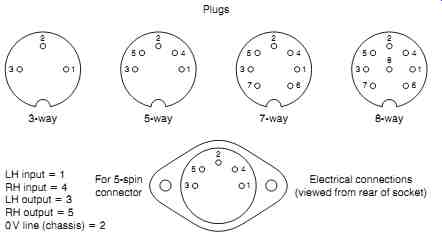
FIG. 1: Common DIN connector configurations.
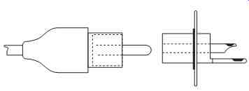
FIG. 2: The phono connector.
3 Gramophone (phono) Pick-Up Inputs
Three broad categories of pick-up (PU) cartridges exist: the ceramic, the moving magnet or variable reluctance, and the moving coil. Each of these has different output characteristics and load requirements.
3.1 Ceramic Piezo-Electric Cartridges
These units operate by causing the movement of the stylus due to groove modulation to flex a resiliently mounted strip of piezo-electric ceramic, which then causes an electrical voltage to be developed across metallic contacts bonded to the surface of the strip. They are commonly found only on low-cost units and have a relatively high output signal level, in the range 100-200 mV at 1 kHz.
Generally, the electromechanical characteristics of these cartridges are tailored so that they give a fairly flat frequency response, although with some unavoidable loss of HF response beyond 2 kHz, when fed into a preamplifier input load of 47,000 ohms.
Neither the HF response nor the tracking characteristics of ceramic cartridges are particularly good, although circuitry has been designed with the specific aim of optimizing the performance obtainable from these units.
However, in recent years, the continuing development of PU cartridges has resulted in a substantial fall in the price of the less exotic moving magnet or variable reluctance types so that it no longer makes economic sense to use ceramic cartridges, except where their low cost and robust nature are of importance.
3.2 Moving Magnet and Variable Reluctance Cartridges
These are substantially identical in their performance characteristics and are designed to operate into a 47-K load impedance, in parallel with some 200-500 pF of anticipated lead capacitance. Since it is probable that the actual capacitance of the connecting leads will only be of the order of 50-100 pF, some additional input capacitance, connected across the phono input socket, is customary. This also will help reduce the probability of unwanted radio signal breakthrough.
PU cartridges of this type will give an output voltage that increases with frequency in the manner shown in FIG. 3(a) , following the velocity characteristics to which LP records are produced, in conformity with the Recording Industry Association of America (RIAA) recording standards. The preamplifier will then be required to have a gain/frequency characteristic of the form shown in FIG. 3(b) , with the deemphasis time constants of 3180, 318, and 75 µs, as indicated in the figure.
The output levels produced by such PU cartridges will be of the order of 0.8-2 mV/cm/s of groove modulation velocity, giving typical mean outputs in the range of 3-10 mV at 1 kHz.
3.3 Moving Coil Pick-Up Cartridges
These low-impedance, low-output PU cartridges have been manufactured and used without particular comment for very many years. They have come into considerable prominence in the past decade because of their superior transient characteristics and dynamic range as the choice of those audiophiles who seek the ultimate in sound quality, even though their tracking characteristics are often less good than is normal for MM and variable reluctance types.
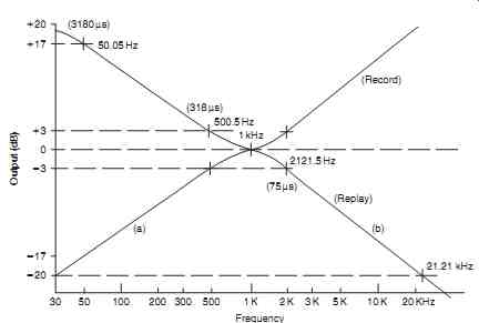
FIG. 3: The RIAA record/replay characteristics used for 33/45 rpm vinyl discs.
Typical signal output levels from these cartridges will be in the range 0.02-0.2 mV/cm/s into a 50- to 75-ohm load impedance. Normally, a very low-noise head amplifier circuit will be required to increase this signal voltage to a level acceptable at the input of the RIAA equalization circuitry, although some of the high output types will be capable of operating directly into the high-level RIAA input. Such cartridges will generally be designed to operate with a 47-K load impedance.
4 Input Circuitry
Most of the inputs to the preamplifier will merely require appropriate amplification and impedance transformation to match the signal and impedance levels of the source to those required at the input of the power amplifier. However, the necessary equalization of the input frequency response from a moving magnet, moving coil, or variable reluctance PU cartridge, when replaying an RIAA preemphasized vinyl disc, requires special frequency shaping networks.
Various circuit layouts have been employed in the preamplifier to generate the required
RIAA replay curve for velocity sensitive PU transducers, and these are shown in FIG. 4 . Of these circuits, the two simplest are the " passive " equalization networks shown in
FIGs. 4(a) and 7.4(b) , although for accuracy in frequency response they require that the source impedance is very low and that the load impedance is very high in relation to R1 .
The required component values for these networks have been derived by Livy 2
in terms of RC time constants and set out in a more easily applicable form by Baxandall 3 in his analysis of the various possible equalization circuit arrangements.
From the equations quoted, the component values required for use in the circuits of
FIGs. 4(a) and 7.4(c) would be RR CR CR 12 11 22 6 818 2187 109 /s and s __ _ . __ µµ
For the circuit layouts shown in FIGs. 4(b) and 7.4(d) , the component values can be derived from the relationships: RR CR CR 12 11 22 12 38 2937 81 1 /s and s __ _ .. __ µµ
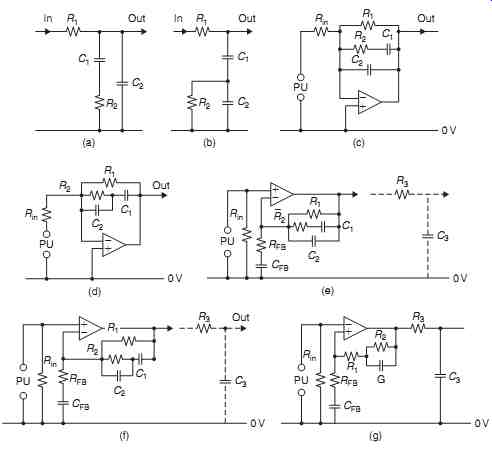
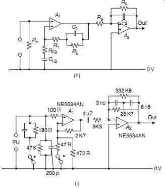
FIG. 4: Circuit layouts that will generate the type of frequency response
required for RIAA input equalization.
The circuit arrangements shown in FIGs. 4(c) and 4(d) use "shunt" type negative feedback (i.e., that type in which the negative feedback signal is applied to the amplifier in parallel with the input signal) connected around an internal gain block.
These layouts do not suffer from the same limitations with respect to source or load as the simple passive equalization systems of FIGs. 4(a) and 4(b) . However, they do have the practical snag that the value of Rin will be determined by the required PU input load resistor (usually 47k for a typical moving magnet or variable reluctance type of PU cartridge), and this sets an input " resistor noise " threshold, which is higher than desirable, as well as requiting inconveniently high values for R1 and R2 .
For these reasons, the circuit arrangements shown in FIGs. 4(e) and 7.4(f) are found much more commonly in commercial audio circuitry. In these layouts, the frequency response shaping components are contained within a "series" type feedback network (i.e., one in which the negative feedback signal is connected to the amplifier in series with the input signal), which means that the input circuit impedance seen by the amplifier is essentially that of the PU coil alone and allows a lower midrange " thermal noise " background level.
The snag, in this case, is that at very high frequencies, where the impedance of the frequency-shaping feedback network is small in relation to RFB , the circuit gain approaches unity, whereas both the RIAA specification and the accurate reproduction of transient waveforms require that the gain should asymptote to zero at higher audio frequencies.
This error in the shape of the upper half of the response curve can be remedied by the addition of a further CR network, C3 / R3 , on the output of the equalization circuit, as shown in FIGs. 4(e) and 4(f) . This amendment is sometimes found in the circuit designs used by the more perfectionist of the audio amplifier manufacturers.
Other approaches to the problem of combining low input noise levels with accurate replay equalization are to divide the equalization circuit into two parts, in which the first part, which can be based on a low noise series feedback layout, is only required to shape the 20-Hz to 1-kHz section of the response curve. This can then be followed by either a simple passive RC roll-off network, as shown in FIG. 4(g) , or by some other circuit arrangement having a similar effect, such as that based on the use of a shunt feedback connected around an inverting amplifier stage, as shown in FIG. 4(h), to generate that part of the response curve lying between 1 kHz and 20 kHz.
A further arrangement, which has attracted the interest of some Japanese circuit designers-as used, for example, in the Rotel RC-870BX preamp, of which the RIAA equalizing circuit is shown in a simplified form in FIG. 4 -simply employs one of the recently developed very low noise IC op-amps as a flat frequency response input buffer stage. This is used to amplify the input signal to a level at which circuit noise introduced by succeeding stages will only be a minor problem and also to convert the PU input impedance level to a value at which a straightforward shunt feedback equalizing circuit can be used, with resistor values chosen to minimize any thermal noise background rather than being dictated by the PU load requirements.
The use of " application-specific " audio ICs, to reduce the cost and component count of RIAA stages and other circuit functions, has become much less popular among the designers of higher quality audio equipment because of the tendency of the semiconductor manufacturers to discontinue the supply of such specialized ICs when the economic basis of their sales becomes unsatisfactory or to replace these devices by other, notionally equivalent, ICs that are not necessarily either pin or circuit function compatible.
There is now, however, a degree of unanimity among the suppliers of ICs as to the pin layout and operating conditions of the single and dual op-amp designs, commonly packaged in eight-pin dual-in-line forms. These are typified by the Texas Instruments TL071 and TL072 ICs or their more recent equivalents, such as the TL051 and TL052 devices; there is a growing tendency for circuit designers to base their circuits on the use of ICs of this type, and it is assumed that devices of this kind would be used in the circuits shown in FIG. 4 .
An incidental advantage of the choice of this style of IC is that commercial rivalry between semiconductor manufacturers leads to continuous improvements in the specification of these devices. Since these nearly always offer plug-in physical and electrical interchangeability, the performance of existing equipment can be upgraded easily, either on the production line or by the service department, by the replacement of existing op-amp ICs with those of a more recent vintage, which is an advantage to both manufacturer and user.
== == ==