Paul Klipsch's famous "Ho, hum, another major breakthrough" applies to the majority of "new" ideas in audio, but on rare occasions a new idea does appear on the scene. In the past no conscientious acoustical expert would presume to design a predictable, controlled acoustic environment for the reproduction of music in a small room.
However, this can now be done, a situation which truly rates the "major breakthrough" title, thanks to the application of time-delay spectrometry (TDS) techniques to small rooms.
Since writing the article on time de lay spectrometry (invented by Dick Heyser) for the January, 1978, issue of Audio Magazine, TDS has experienced a literal explosion of growth. This intense activity has stemmed from the availability of apparatus and the discovery of TDS applications that are fundamental to the recording industry.
TDS in the Control Room
After initial exposure to the TDS technique, we included the apparatus in the recording studio control room consulting job we had at hand. A first look at this environment revealed difficulties in the response of the direct sound from the monitor loudspeakers and then an overwhelming mass (or mess) of early reflections as the analyzer's filter looked at the swept signal later and later in time. To be able to return to looking at the "total sound field" by means of our 1/3-octave real time analyzer (RTA) was a relief.
In thinking over what had been observed with the TDS apparatus, several "first principles" of acoustics were brought freshly to mind. The first was that two sources emitting sound at the same frequency in the crossover region cause serious difficulty if they do so at different distances from the listener and/or measuring instrument.
See Fig. 1 as an illustration of how comb filter effects are generated by the difference distances from two sources. TDS shows that lining up a woofer and a tweeter at exactly the crossover frequency does no good because the apparent acoustic center is changing with frequency throughout the crossover region (at least two octaves). The results on occasion are almost catastrophic. Figure 2 shows the direct response of a very widely used three-way monitor first with its tweeter in normal operation and then (Fig. 3) with a hand placed over the tweeter. The acoustic centers of the midrange and tweeter are over one foot apart at the crossover frequency.
The mixer in this particular control room, who has really well trained ears, had been complaining that there was something wrong with the sound in the room. (Once heard, this type of distortion becomes quite intolerable thereafter.)
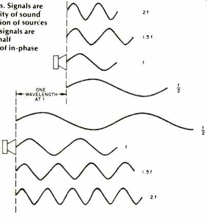
Fig. 1--Calculating addition and cancellation of signals. Signals are in
phase every (velocity of sound in ft. per sec./separation of sources in ft.)
in Hz and add; signals are out of phase at each half wavelength multiple
of in-phase points and cancel.
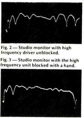
Fig. 2--Studio monitor with high frequency driver unblocked.
Fig. 3--Studio monitor with the high frequency unit blocked with a hand.
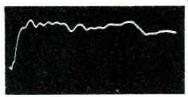
Fig. 4--Direct sound field of a studio monitor. Response is from 0 to 10,000
Hz.
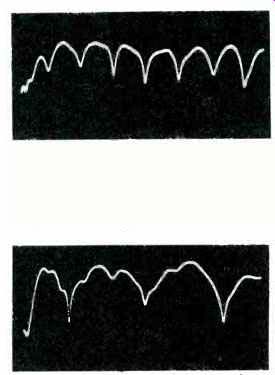
Fig. 5 Direct and reflected sound field of a studio monitor. Total distance
between the direct and reflected sound field is 13.56 feet; response as in
Fig. 4.
Fig. 6--Total distance between the direct and the reflected sound field is 6.78 feet.
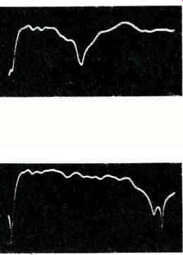
Fig. 7 Total distance between the direct and reflected sound field is 4.52
feet.
Fig. 8 Total distance between the direct and the reflected sound field is 1.94 feet.
The second fundamental is that a reflection can serve very adequately as a second source and that the time delay between the direct sound spectrum from a monitor and a reflected sound spectrum can and does combine in violent comb filter effects.
One important parameter instantly observed is that the longer the time delay between arrival of the direct and reflected sound spectrums, the narrower and more frequent the anomalies (the peaks and dips). The shorter the time difference between arrivals, the wider and less frequent the anomalies. See Figs. 4-8.
Triggered no doubt by our experience in the equalization of sound systems, we instantly realized that wide band anomalies are dangerous because of the power that can be present in that bandwidth. It is today a well established fact that bandwidths substantially narrower than one-third of an octave are a relatively undetectable entity in a broadband complex signal and that the ear cannot respond to the spectrum shape within such a narrow band (critical bandwidth theory). We reached the conclusion that early reflections are not desirable in a playback monitor. This was an interesting insight, inasmuch as a majority of the control rooms we were working in had surfaces near the monitors which were hard and the rear wall as dead as it was possible to make it. The evidence indicated that, more than likely, something was awry.
A remark made by Ed Long and Ron Wickersham more on these two later put another piece in the puzzle; they revealed they were placing their Pressure Response Pickup (PRP) microphones the so-called Hass distance apart.
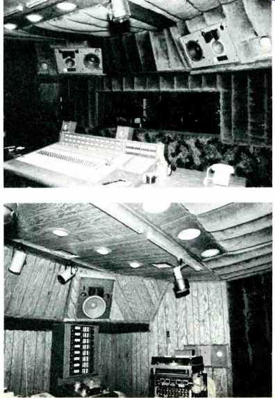
Fig. 9--The dead end of the control room built by Chips Davis at Las Vegas
Recording. Fig. 10--The live end of the control room at Las Vegas Recording.
Live End, Dead End
In discussing these insights with a Syn-Aud-Con class in Anaheim, Chips Davis (no relation to the authors), co-owner of Las Vegas Recording as well as sound engineer for Wayne Newton, decided to rebuild his control room under the guidance of the principles discussed in class. The results are shown in Figs. 9 and 10.
When Chips called us to come and hear the control room we took with us a knowledgeable control room designer and studio owner, Bill Putnam of United Recording. The hard, diffuse rear wall was totally inaudible. If one turned and faced the rear wall and cupped one's ears, not a sound could be heard off the rear walls. Why? Because the mixer's position was squarely in the center of the Henry or Haas effect fusion zone. A remarkable paper written by Professor Joseph Henry for the Smithsonian Institution and presented to them in 1856 (on work done in 1849) discusses the effect: If ... we stand at half this distance (half the distance sound travels in 1 sec.) before a wall, the echo will return to us in one second. It is, however, a fact known from general experience, that no echo is perceptible from a near wall, though in all cases one must be sent back to the ear.
Professor Henry went on in experimentation to establish that the effect ran to about 30 feet or 1/16 of a second. Modern researchers have found that for spaces with the acoustic characteristics of control rooms that about one-half this time is optimum. Remember Professor Henry's experiments were done outdoors without modern timing apparatus. This effect has had many names, the latest being Haas, and the entire history of the reinvention or rediscovery of this effect was covered thoroughly by Mark B. Gardner's article, "Some Single and Multiple Localization Effects," in the Journal of the Audio Engineering Society, July-August, 1973, Vol. 21, No. 6.
Turning around in the Las Vegas Recording control room and facing the anechoic end, it was as if the wall between the studio and the control room had been knocked down. As the mixing engineer remarked, "I now hear exactly what is happening in the studio. Successful mixes are reached in half the usual time since the control room has been reversed." In essence, the control room is now a controlled acoustic environment without significant coloration of its own and accurately reflecting (within the capabilities of the monitor loudspeakers and the studio microphones) what is happening acoustically in the studio. This approach is referred to as the "live end, dead end" technique (LEDE) and is now underway in a number of control rooms.
Implementing the LEDE Approach In addition to the usual cares for isolation, etc., necessary in the design of a control room, the LEDE technique requires great care in the following areas:
1. The room geometry must eliminate early reflections and very late reflections.
2. The hard end must be diffuse, without long paths, and provide relatively equal distances for reflections to the mixer's ears that fall in the 10 to 25 mS range. See Fig. 11 for a rough sketch of the general characteristics. In thinking over the outstanding results Chips received from his efforts, the realization that this approach had been indicated over and over again through the years was increasingly apparent.
An anechoic chamber is eminently unsuited for mixing music primarily due to its unnatural environment and the fact that there are no reflections, early, middle or late, to help smooth out the comb filter effects generated whenever the mixer is not exactly centered between two monitors. A reverberation chamber is quickly discarded as a control room after one experience.
Therefore, in spite of contemporary attempts to make the mixer's ears location nearly anechoic, it is a diffuse, mixing, semi-reverberant environment that is really desired (note all the nonsense about coherent summing of monitors, +6 dB for combined acoustic signals from monitors). Failure to achieve such an environment is due, in our opinion, to many designers thinking that what works well in a large arena or auditorium, namely dead back walls, could be scaled down to control rooms. It is clearly evident that control room designers minus TDS equipment and experience in its use are like blind men instructing sighted persons in perspective drawing.
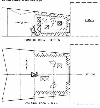
Fig. 11 Rough approximation of how the control room should be set up.
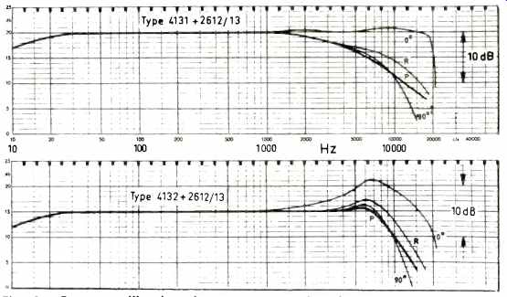
Fig. 12--Free-field calibration of a pressure type microphone.
Fig. 13--Pressure calibration of a pressure type microphone, showing rise in response with 0-degree incidence wave.
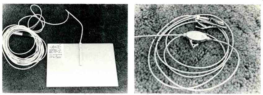
Fig. 14--A pressure response microphone designed by Ken Wahrenbrock, Downey,
CA. Fig. 15--A lavalier-type PRP microphone.
The Pressure Recording Process
An equally dramatic offshoot of TDS and one that will be experienced by most listeners sooner than the LEDE effect is the PRP Technique of Ed Long and Ron Wickersham. Long is the inventor of Time Aligned loudspeakers wherein electronic networks are employed to keep low frequency and high frequency signals in the crossover region in time alignment through the entire region. Ed later became associated with Ron Wickersham, Chief Engineer and co-owner of Alembic, Inc.
Greatly annoyed with multichannel mono records, Ed and Ron set out to make some true stereophonic recordings that retained the amplitude, phase, and time differences present at a live performance true spatial geometry as well as a solid curtain of sound.
Again TDS demonstrated that a microphone first receives the direct sound from a musician, followed by the room reflections natural to the musician's location. So far so good, but the microphone also sees (or hears) the early reflections from surfaces near the microphone. Ed and Ron reasoned that a flush-mounted microphone would be free of such anomalies. True, but such a flush mounted microphone should be a pressure response type (See Figs. 13 and 14), but when a signal arrives at the pressure microphone's 0 degree incidence, an unwanted peak in the response occurs. They then realized that a pressure response microphone placed in opposition to a reflective surface, a few thousandths of an inch away, would never see a 0 degree incidence signal and the pressure response calibration would always be accurate. One of the results has been the special model shown in Figs. 15 and 16 designed by Ken Wahrenbrock of Downey, CA. Wahrenbrock calls his system the Pressure Zone Microphone°, recognizing that a pressure capsule not in a pressure zone fails to provide the benefits sought.
TDS Equipment
When we first reported to you on TDS last January, TDS apparatus cost over $12,000. Currently it costs under $5,000, and it is reasonable to expect it to drop to the $2,500 range. The equipment can be rented for under $500 per month. It means that a serious loudspeaker designer, experimenter, or small manufacturer no longer needs a $100,000-plus anechoic chamber but can actually measure with greater accuracy, in his own living room if he wishes, the direct, reflected, and total sound fields from a loudspeaker. Figure 17 shows the equipment currently used by us. Those wishing a license to practice TDS should send a check for $100 made out to the California Institute Research Foundation but mailed to Syn-Aud-Con, and a check for $25 made out to Syn-Aud-Con for a set of "how to" notes on TDS. (Syn-AudCon, P O Box 1134, Tustin, CA 92680) The list of TDS licensees is growing at a rapid rate, especially considering that until the Spring of 1978 there was only one licensee. The increasing knowledge that comes from the use of TDS is going to have an enormous impact. The licensees are:
Cecil Cable, Cecil Cable Assoc., Edmonton, Alberta; Marshall Buck, Ph.D.; Don Davis, Synergetic Audio Concepts, Tustin, CA; Alan Feierstein, Acoustilog, New York; Richard Jamieson, Jamieson & Assoc., Minneapolis; Walt E. Disney Enterprises, Burbank, CA; K. A. Wahrenbrock, Wahrenbrock Assoc., Downey, CA; Ed Lethert, MTS Northwest, Inc., Minneapolis; Timothy J. Clark, Huntington Beach, CA; William M. Peterson, Jr., Reston, VA; Richard Blinn, Capitol Records, Inc., Hollywood, CA; John E. Payne, Westlake Audio, Los Angeles, CA; D.F. Morris, UREI, Sun Valley, CA; Ed McGee, Acoustic Control Corp, Van Nuys, CA; Nelson Rose, Maple Glen, PA; A. J. Martinson, Martinsound, Alhambra, CA; J. G. Mitchell, Schaumburg, IL; Richard C. Coscia, Heavy Custom Sound & Light, Brooklyn; John W. Kryda, G&T Harris Inc., New York; David M. Andres, Andrews Audio Consultants, New York; Glen Ballou, Southington, Conn.; John J. Klanatsky, Astoria, NY; Brett Cosor, Electronic Marketers, Gaithersburg, MD; Mark Lynch, Quality Sound Enterprises, Fayetteville, NC; Camillo/Barker Enterprises, Somerville, NJ; John Laberdie, Dale Ashby & Father, Basking Ridge, NJ; Robert Brown, J.F.A. Electronics, Troy, NY; Ray Rayburn, Rayburn Electronics, Glendale, NY; Robert V. Vitale, Pittsfield, MA; Don Mowry, Marguerite's Music, Moorhead, MN; Eugene T. Patronis, Ph.D., Dunwoody; GA; Klipsch & Associates, Hope, Arkansas; Bob Todrank, Valley Audio, Nashville, TN; Farrel M. Becker, Kensington, MD; Robert Daniel, Eleven Ninety One, Inc., Clarksville, TN; Don Heavener, Miami, FL; Bobby Lin and Bjorn Matz, Sound Systems, Inc., Long Island City, NY; Thomas C. King, Walt Disney World, Buena Vista, FL; Robert C. Herrick, Production Consultants, San Antonio, TX; Kenneth L. Hartz, Orlando, FL; Lillian Sarbey, Sarbey Systems Corp., Miami, FL, and Ted L LeTourneau, Acoustic Consultants, Longview, TX.
Syn-Aud-Con is licensed by the California Institute Research Foundation to teach TDS, and those wishing instruction can attend the current Syn-Aud-Con classes. PRP records are available from Sumiko, P.O. Box 5046, Berkeley, CA 94705, $9.00 each. Time Align loudspeakers are manufactured by UREI and Sonex. Some of you can and will approximate the LEDE approach in your homes. When you have, you will appreciate how many audio engineers are manacled by conventional, large room, statistical acoustic concepts.
It is with genuine pleasure that we share these insights, obtained via TDS, into the "combinational geometry" and practical psychoacoustics underlying successful control of a small room's acoustic environment. The functional truth regarding playback systems in small rooms, such as control rooms and home music rooms, once experienced, is simple to understand, easy to apply, and immediately obvious to anyone who hears the results.
-----------
(Source: Audio magazine, Jan. 1979; Don Davis [Synergetic Audio Concepts, Tustin, Calif.] )
Also see:
TDS (time delay spectrometry) in Sound Measurements (Jan. 1978)
= = = =