by Matthew Polk

[Matthew Polk is Chairman of the Board and Vice President/Engineering of Polk
Audio, Baltimore, Md.]
When made commonly available in the 1950s, stereo revolutionized the quality of reproduced sound. Originally conceived before the turn of the century, stereo reproduction was not made practical until the invention of a stereo disc recording and playback system at Bell Labs during the early 1930s. Due to the economic effects of the Depression and the turmoil of World War II, stereo was not introduced to the general public until the 1950s. In the interim, many fundamental works on acoustics and sound reproduction were written, but from a strictly monaural point of view. A framework of monaural theory was created, within which sound-reproducing equipment, mainly transducers, was designed and its performance judged. Stereo, in no small measure, owed its success to its superficial compatibility with existing monaural equipment and the fact that engineers could apply familiar monaural concepts to the design of equipment for stereo. The first stereo systems offered were, in fact, two separate and complete mono systems linked by a common volume control and fed by a "new" stereo disc player. The concept of stereo as "dual mono" reproduction continues to this day, especially as regards the design of loudspeakers.
In addition, criteria for measuring the performance of the equipment also remain unchanged from the days of monaural reproduction.

Fig. 1--Localization by Interaural Intensity Differences.
Mono versus Stereo
Stereo is an essentially psychoacoustic phenomenon. That is, a listener is required for the sound localization process to take place. Early experimentation with reproduction of sounds in stereo revealed that the human hearing process perceived certain limitations in the sonic image produced by multiple speaker systems. Using essentially the same speakers as had been used in earlier mono systems, the sound field was perceived to be limited by the physical positions of the loudspeakers. Despite this limitation, stereo imaging was a great improvement over the monaural image, and stereo became an unqualified success. Once stereo was firmly established, attempts were made to present a more complete sound field, the most notable of these attempts being the ill-fated four-channel systems of the '70s. In the mid-'70s, several of us at Polk began to wonder whether it was necessary to use additional channels to create a more realistic sonic image. We could show that, in theory, there was enough information contained in two normal stereo channels to define at least a.180° sound stage, and indications were that even more might be possible. This gave us confidence that a more complete sound stage might be reproduced from existing stereo recordings. Recognizing that the equipment being used to reproduce stereo was basically unchanged from monaural equipment, we saw that we would have to expand our concept of what the equipment was being asked to do. More than asking the equipment simply to reproduce an input signal, we proposed to make the equipment work with, rather than against, psychoacoustic principles, to re-create a sound stage in the listener's mind.
Directional hearing is primarily a binaural process. In simplest terms, the brain compares the sounds heard by the two ears and uses the difference to determine the direction and distance of the sound source. The differences between the sounds at the two ears are perceived in three ways: Intensity, phase, and arrival time. (See Figs. 1 through 5.) In each case, the listener uses two signals, one at each ear, to localize the sound source. However, a stereo system has two speakers, and will provide the listener with a total of four signals (see Fig. 7). The sound from each speaker that crosses the listener's head to the opposite ear is known as interaural crosstalk. Experimenters in directional hearing were the first to be troubled by interaural crosstalk since its existence prevents the independent control of phase and arrival time of sounds at each ear. Interaural crosstalk was also thought to be the primary cause for the limitations on stereo imaging. The obvious solution was, of course, to use headphones, thereby eliminating the interaural crosstalk sound paths. This was a very satisfactory means to an end for psychoacoustic research, but it was not as successful in the reproduction of music. Although the elimination of interaural crosstalk seemed to give significant advantages to headphones, the phones still failed to produce a convincing sonic illusion. Clearly, there were numerous questions still to be answered about the stereo imaging process before approaching the final question of how the reproducing equipment should interact with the listener to produce a believable sonic illusion.

Fig. 2--Localization by Interaural Phase Differences.

Fig. 3--Localization by Interaural Time Delay (ITD), where t is the time required
for sound to reach the nearest ear and .]t is the delay in reaching the other
ear, also known as the Interaural Time Delay.
It seemed natural to focus on the last link in the reproducing chain, the loudspeaker, in an effort to develop the necessary understanding and control of the stereo imaging process. The fact that two loudspeakers could produce a phantom image between them was well known; the basic mechanism is shown in Fig. 7. The major difficulty here is that the two speakers will provide the listener's ears with four signals, whereas only two can be properly used. To avoid confusion, the hearing mechanism selects only one of the two sounds at each ear, according to a principle known as the precedence effect. First described in 1949 by Helmut Haas, the precedence effect simply states that only the first arrival at each ear will be used for directional location (see Fig. 6). It is not difficult to apply this concept intuitively to the stereo listening situation shown in Fig. 7. If both speakers produce the same sound at the same time, the first sound to arrive at each ear will be the direct sound from the speaker on that same side. The second sound at each ear will be the interaural crosstalk signal which has been delayed by traveling the extra distance across the listener's head. Since the direct sounds arrive first, they will be the only ones considered, and since they arrive coincidentally, and with near-equal loudness, the listener will perceive a phantom sound source as if it were centered between the speakers.
Although this situation was easy to analyze intuitively, we realized that more complex cases would be easier to approach with an appropriate mathematical notation. Two quantities characterize each of the signals arriving at the listener's ears, arrival time and intensity. Ignoring any electrical delays, the arrival time of the sound will be proportional to the distance traveled in reaching the ear. Relative intensity is easily expressed as a ratio. So, the signals reaching the ears can be expressed as a function of the time required to reach the ear, multiplied by the sound intensity relative to that at the other ear.
Accordingly, the left and right loudspeaker signals were considered as functions of time. If the time required for the sound from the left loudspeaker to reach the left ear is t, that signal at the left ear would be written as L(t). If the interaural time delay for the same signal to pass across the listener's head to the right ear is at,, then the time required for the left signal to reach the right ear will be t + Δt,. That crosstalk signal would then be written as L(t + Δt1). Using this notation, the signals at each ear in Fig. 7 will be:

From this point on, I will use át, as the notation for the interaural time delay associated with the positions of the loudspeakers.
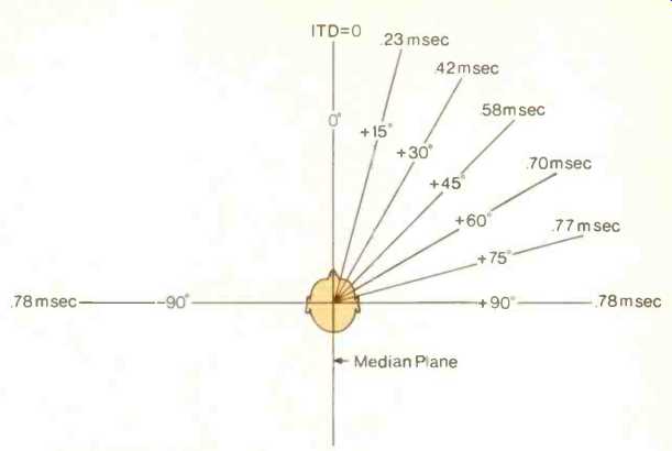
Fig. 4--Experimentally determined values for the interaural time delay for
various angles of incidence.

Fig. 5--The Interaural Difference Spectrum (IDS).
Interaural Crosstalk Distortion
Two speakers will produce a convincing center image-but what happens as the image moves to the side? In Fig. 7, each ear receives two signals, the direct sound followed by the interaural crosstalk signal (Eq. 1). Turning the right speaker off would represent the most extreme leftward shift of sonic image on the basis of interaural intensity difference. Only one signal at each ear would remain:

In the absence of a right-speaker signal, the crosstalk signal becomes the first right-ear arrival and causes the sound to be perceived as coming from the left loudspeaker. The same would happen on the other side if the left channel signal were turned off. The presence of the interaural crosstalk signals effectively cuts off the sound stage at the loudspeaker positions.
Suppose that one channel is delayed relative to the other. This also will cause the sonic image to shift. If right is delayed by át relative to left, we have:


(top) Fig. 6; (above) Fig. 7--Stereo localization of a phantom source. If left
and right channels are of equal loudness and leave the speakers at the same
time, the sound will seem to originate directly between the speakers.
As the right-channel delay increases, the sonic image will shift progressively to the left. As long as the delay of the right channel, _St, is less than the interaural delay, .1t1, for the left-speaker crosstalk signal, localization will be controlled by the right channel signal. When the right-channel delay exceeds the crosstalk delay, the interaural crosstalk signal will become the first arrival and will again limit the image shift to the position of the loudspeaker. It began to appear to us that the existence of the interaural crosstalk signals caused the stereo image to be linked more to the positions of the loudspeakers than to the musical content of the stereo signals.
Next, we tackled the problem of headphones. Despite the fact that headphones eliminate interaural crosstalk, they still do not usually produce a convincing stereo image. We looked again at one channel delayed relative to the other. The signals at the ears for headphones were the same as those in Eq. (3), but without the crosstalk terms.
Accordingly, for right delayed relative to left:

Assuming the left- and right-ear signals are of roughly equal intensity, localization of the sound will be entirely controlled by the time delay, _St. The sonic image will shift to the left as the magnitude of the delay increases.
When the delay becomes equal to the maximum naturally occurring interaural time delay, Δtmax (see Fig. 3), the sonic image will be shifted all the way to the left. If the delay between channels increases further, what will happen? The image can shift no further! The directional hearing mechanisms are closely related to the physical dimensions of the head and ears. The maximum naturally occurring interaural time delay (ITD) corresponds to the distance between the ears, roughly 63 inches. If the apparent ITD presented by the headphones is increased to correspond to a distance of several feet, the listener cannot respond in any predictable way. It would be like trying to locate the direction of a sound while holding long cardboard tubes against each ear.
As we saw in Eq. (3), the interaural crosstalk signals produced by loudspeakers limit the side-to-side image shift. But, in doing so, they also prevent the problem of non-localizable sounds that occurs with headphones.
In Fig. 8, sound sources A through F are shown being recorded by two microphones set the same distance apart as a person's ears. Loudspeakers tend to localize everything as being in front.
This is because the positions of the loudspeakers forward of the listener, obviously, must create the appropriate frequency spectra at each ear for forward localization. The bottom half of Fig. 8 shows the apparent positions of the sounds when played back over two mono loudspeakers. Due to the limitations we have just discussed, the sonic images of sounds C through E will "pile up" in the same direction as the left loudspeaker while the sounds A and B will have distinct images between the speakers.
Although this piling up of sound images is observed on many recordings, the prediction that the image could spread no further than the loudspeaker positions was initially disturbing.
Sometimes a single pair of loudspeakers can produce a sonic image which extends slightly outside the bounds of the speaker positions. We realized that in each case where we had observed this, the speakers were placed very close to the listener and had some unusual directional characteristics which, we speculated, were contributing to a partial elimination of interaural crosstalk sound paths. This was not a measurable phenomenon, but it opened our minds to the idea that interaural crosstalk could be eliminated by acoustic methods.
The Full Potential of Stereo
Although binaural recording techniques have produced startling results with headphones, our goal was to reproduce a more complete sound stage from existing stereo recordings. Binaural recordings being in regrettably short supply, we realized that, whatever system was devised, it would have to cope with the broad range of available recordings. Consideration of prevalent recording practices within the context of the directional hearing mechanisms had revealed that the sound imaging abilities of both loudspeakers and headphones were limited, but in different ways. The width of sound stage presented by loudspeakers is limited by interaural crosstalk.
The stability of the sonic image of headphones is limited by the lack of realistic directional cues. This meant that we would have to do more than eliminate interaural crosstalk. In addition, we would have to find a way for the directional cues contained in the recordings, such as they are, to reach the listener's ears in a manner acceptable to the hearing process.
Rather than trying to imagine what nature of speaker system might do all of these things and still sound good, it seemed more appropriate to try to capture our needs in mathematical notation. We wanted a system which, when balanced all to one channel, would provide the listener with a sonic image directly to the side, at 90°, but which would remain stable regardless of the interchannel delay. The signals required for a left-side signal would be:

Conversely, a right-side signal would be:

Adding these will give the more general case for both channels operating:

The second term at each ear looks very much like a crosstalk signal with an ITD equal to Δtmax, but in reality it is sort of a stabilizing dimensional signal which limits the perceived ITD to values within the naturally occurring range.
===============
A Directional Hearing Primer
Directional hearing works mainly by comparing the sounds heard by the two ears of a listener. Specifically, three quantities are compared, intensity, phase, and arrival time. A sound arriving from one side of the head will be partially blocked in reaching the ear on the other side, giving rise to a difference in loudness between the two ears (see Fig. 1). The precise difference created depends both on the angle of incidence of the sound and on the frequency. The unique combination of loudness difference and frequency is linked to the angle of incidence of the sound in the horizontal plane. High frequencies are blocked more easily by the head, leading to greater loudness differences.
Intensity differences also play a role in locating complex sounds. For a given angle of sound incidence, each frequency has its own characteristic loudness difference. The sum of these will create an interaural difference spectrum (IDS) which corresponds to a specific angle of incidence (see Fig. 5). The exact characteristics of these difference spectra enable the listener to distinguish between sounds coming from the front and sounds coming from the rear.
In addition, the hearing mechanism is sensitive to the difference in relative phase of a sound which appears at both ears, though this is limited to continuous tones. A sound arriving from one side of the head experiences a time delay in reaching the farther ear. The listener senses an interaural phase difference which depends on the angle of incidence of the sound and on the frequency (see Fig. 2). However, for higher frequencies the phase lag may become greater than 180° and hence indistinguishable from a phase lead in the opposite direction. Appropriately, the hearing mechanism is relatively insensitive to phase differences above 900 Hz, a frequency whose half wavelength is nearly equal to the interaural distance.
Transient sounds are localized mainly on the basis of the difference in arrival time at the two ears. Since most naturally occurring sounds are transient, this is both the most important and most accurate method of directional location. The interaural time difference (ITD) increases roughly as the sine of the angle of sound incidence up to 90° left or right of the median plane. At this point the sound must travel entirely across the head to reach the far ear, and the ITD becomes equal to Δtmax (see Fig. 3). Figure 4 shows experimentally determined values of ITD versus angle of incidence.
Finally, two related mechanisms, forward masking and the precedence effect, help the listener to discriminate between the many sounds reaching the ears at any given time (see Fig. 6). Basically, if two similar sounds of equal loudness arrive at one of the listener's ears separated by a short period of time, the listener will hear only one sound but of greater loudness than either of the individual sounds. The maximum interval for forward masking of musical sounds in a live room is about 35 mS. However, the maximum interval for masking of test clicks over headphones may be as low as 3 mS. The precedence effect is observed in the case of two signals at each ear, where the perceived direction of the sound source will be determined on the basis of the arrival of the first sound at each ear.
An example of phantom source localization from two speakers is shown in Fig. 7. Here, each ear receives two signals, one from each speaker. However, due to the precedence effect, only the first sound at each ear is considered. These are the direct sounds from each speaker, labeled L(t) and R(t). If the listener is centered between the speakers, these sounds will arrive at the same time. If they are also of approximately equal loudness, a phantom sound source will be perceived midway between the speakers.
In practice, most stereo image location takes place on the basis of intensity differences. This is due to the existence of interaural crosstalk signals which restrict the possible range of interaural time delays. As shown in Fig. 8, the location of phantom sound sources is limited to within the loudspeaker positions.
M.P.
===============

Fig. 8--Normal stereo imaging with sounds recorded by two microphones at locations
A through F. When reproduced by two mono loudspeakers, the existence of interaural
crosstalk will limit the phantom images to the locations shown in the lower
half.
At this point, we made a decision that the sound sources, whatever they might be, should be placed in a forward position relative to the listener.
This would eliminate the need for any complicated filtering to replicate the necessary interaural intensity differences for forward localization of sounds. However, if the sound sources were loudspeakers we would again be limited by the existence of interaural crosstalk signals. If we include the crosstalk signals in the expressions for the idealized signals above, we then have:

The second term at each ear is the crosstalk signal, which arrives earlier than the desired dimensional signals represented by the third terms. In order to take advantage of the later-arriving dimensional signals, the crosstalk signals would have to be eliminated or substantially reduced in loudness. Recalling that we had observed partial elimination of crosstalk signals due to unusual directional characteristics, and recalling the well-known phenomenon of low-frequency cancellation between two out-of-phase speakers, we guessed that it might be possible to acoustically cancel the interaural crosstalk signals. If this were done, the signals at the ears would be:

The new third term in each expression should be thought of as a phase inverted equivalent of the crosstalk signal, timed to arrive at the correct ear at the same time as the original crosstalk signal. This was a very attractive idea, but we were not at all sure how it would be accomplished.
Timing the Delay
In order to cancel the crosstalk, a phase-inverted version of the sound could be acoustically delayed to arrive at the proper ear at the precise time to cancel the crosstalk signal. Creating the acoustic delay is no great trouble--you simply place the sound source farther away. It immediately seemed that if we had two pairs of acoustic sources, it would be possible to do this; the idea was to use one pair to cancel the crosstalk produced by the other. The cancellation source would have to be the same distance from the ear where the cancellation was to occur as the main source whose crosstalk signal was to be cancelled. In addition, the cancellation source should be placed so as to minimize cancellation of the direct sound reaching the other ear. Figure 10 shows an arrangement of drivers which allows the proper cancellation to take place. The signals arriving at the two ears for this arrangement would be:

Here t + .it' is the time required for the sound from the cancellation drivers to reach the nearest ear. So long as Δt' is equal to Δt1, the main driver crosstalk signals (second term) will be cancelled by the direct sound from the cancellation drivers (third term). The fourth terms are the crosstalk signals generated by the cancellation speakers themselves. For each ear they are the same signal as the direct sound from the main driver (first term), but arrive considerably later. Due to the precedence effect, they will not interfere with the localization process.
The placement of drivers shown in Fig. 10 also answered the requirement that the listening position be flexible.
The center-to-center distance between the main and cancellation drivers on each side is the same as the distance between a person's ears, roughly 63 Inches. As long as the listener remains on the axis between the two speakers and the cabinets face straight forward, sound from the cancellation drivers will arrive at the proper time to cancel the crosstalk signals regardless of how close or far away the listener sits. The remaining problem with this arrangement, however, was the lack of the stabilizing dimensional signals necessary to prevent the type of non-localizable sounds that can occur with head phones. Consider the effect of having no right-channel signal on this system:

In nature, a sound is not normally heard in one ear only, and, presented with such a situation, a listener would not be able to assign an accurate direction to the sound. The solution to this problem was to use a stereo difference signal as both the dimensional and the cancellation signal. The difference signal has long been known to contain mostly ambient information, but in this case, we recognized that its components represented the two signals that we needed. The R L signal was fed to the right dimensional/cancellation driver, and the inverse signal, L R, was fed to the left dimensional/ cancellation driver. In each case the positive portion of the difference signal is the stabilizing dimensional signal, while the negative portion is the cancellation signal. The entire system is shown in Fig. 11. The resulting signals at each ear would be:

Writing these out in plain language, without reference to the particular speakers, we have:
(Signals arriving at the ear) = (main driver direct signal) + (dimensional driver direct signal) + (main driver crosstalk signal) (dimensional driver direct signal) (dimensional driver crosstalk signal) + (dimensional driver crosstalk signal).
In all, each ear receives six signals.
For clarity the equation has been labeled to indicate the driver from which the signals originate. Crosstalk signals break the median plane in reaching the ear in question, whereas the direct signals do not. The various time delays are defined as follows: t = time required for sound from main driver to reach nearest ear.
t + Δt' = time required for sound from dimensional driver to reach nearest ear.
Delta_t’= ITD for main driver crosstalk sound to reach opposite ear.
Delta_t1= ITD for dimensional driver crosstalk sound to reach opposite ear.
Δtmax = the maximum naturally occurring ITD. At this point it appears helpful to explain each term. Term 1: The direct sound from the main driver will be the first arrival at the ear and will be the primary sound used by the localization process when the sonic image shifts for sounds on that side. Term 2: The positive component of the direct sound from the dimensional driver. Since it is the same signal as the first term, but arrives later, it will always be ignored by the localization process. Term 3: The main driver crosstalk signal; if it were not cancelled, it would limit the width of the sonic image. Term 4: The inverted component of the direct sound from the dimensional driver, otherwise known as the cancellation signal. It arrives coincidently with the main driver crosstalk signal and cancels it.
Term 5: The inverted portion of the dimensional driver crosstalk signal is also a late arrival and will be ignored in the localization process. Term 6: The positive portion of the dimensional driver crosstalk signal, or dimensional signal; it insures a stable sonic image by placing an upper limit on the possible values of perceived ITD generated by the system.
Now, if we turn off the right channel sound as we did in Eq. (11), keeping in mind that for this arrangement _Δt' equals Δt1, the signals at the two ears are

With signals at both ears, the listener will have no trouble localizing the direction of the phantom sound source.
The perceived ITD will be the sum of Δt' and Δt1, which will produce a phantom image well outside the speaker positions as shown in Fig. 11.

Fig. 9--Stereo dimensional imaging. If the interaural crosstalk signals are
cancelled, the stereo stage will be unrestricted, allowing proper imaging of
sound sources A through E. Sound source F will still be ambiguously located
due to the lack of front-to back directional cues.

Fig. 10--Geometry for providing flexibility of listener location.
Cancellation drivers are placed at the interaural distance from the main drivers and just outside them. The left cancellation driver receives the inverted right signal and vice versa.
Proper cancellation of interaural crosstalk will occur for any location on the central axis between the speakers.

Fig. 11--Block diagram of complete stereo dimensional speaker system.
Use of stereo difference signals at the cancellation drivers provides necessary image stabilization cues and limits the induced /TD of the system to naturally occurring values.
Optimum sound-stage width occurs when the listener forms an equilateral triangle with the speakers.
The Stereo Dimensional Loudspeaker
The stereo dimensional speaker system described here in theoretical terms seems to offer all that we had hoped for. Using the theory we had developed as a guide, we set about constructing prototypes of what we hoped would be the first loudspeaker system capable of realizing the stereo imaging and dimensional capacity of available program material. The prototypes were constructed with four identical sets of drivers for the main and dimensional arrays. The Polk 6 1/2-inch mid-woofer was used since its size allowed, precisely, for the interaural spacing of 63/4 inches required between the main and dimensional arrays on each side. In addition, the wide frequency response of the driver would cover most of the frequency range crucial for directional location. We constructed a single cabinet to house both of the driver arrays on each side, which fixed the geometrical relationship between them. The left and right speaker cabinets were interconnected with a cable to provide the components of the stereo difference signal to the dimensional drivers, and a complex crossover matrix was designed to provide the correct frequency response for each array as well as the critically important phase relationships between them. As soon as the prototypes had been debugged, we hooked them up to some music. It was immediately apparent to us that the idea was a success.
As each set of prototypes was completed, tested and evaluated, more unsuspected pieces of information were uncovered. The finished system shown in Fig. 12 contains many important features discovered during the refinement process. For example, phase matching between the main and dimensional arrays was found to be necessary at surprisingly low frequencies, well below 100 Hz. As a result, the main and dimensional drivers of the finished system share the same acoustic volume, ensuring that they will see identical acoustic loading. However, the most significant realization coming out of the refinement process was of the complete inadequacy of our existing measurement techniques to assess the performance of this system. Although we have since made considerable progress in developing a more relevant measurement system, the human ear remains our most discriminating design tool.
Audible Benefits
The finished system, in many respects, has exceeded our expectations. The flexibility of listening position is greater than was expected, allowing not only front-to-back movement, but substantial side-to-side tolerance as well. Analysis of signals at the ears for listening locations off the central axis somewhat justifies this, but predicts a more dramatic image shift than the "changing seats in a concert hall" effect actually observed. More easily explained is the observation that phantom sources localized to the sides seem to remain stationary as the listener moves away from the system, rather than moving with the listener. As we recall from Fig. 11 and Eq. (13), the perceived ITD will be the sum of Δt’ and Δt1. Due to the geometry of the system, this quantity will decrease as the listener moves away, causing the sound stage to narrow and preserving the perspective of greater distance.
Less explainable, however, is the experience of having some sounds seem to actually originate from the rear of the listening area. Since this occurs primarily on pop recordings, we can only speculate that the recording studio has inadvertently created an interaural difference spectrum appropriate for rearward localization. Nevertheless, the effect is startling.
The newly designed Polk SDA systems are, we think, the world's first true stereo loudspeakers, strongly realizing the capabilities of the stereo medium.
The unique ability of the system to place sonic images over an unrestricted stereo stage allows the listener to hear the recorded instruments or vocalists firmly located in the original acoustic environment. In addition, due to the system's preservation of directional information, each sound becomes better separated and more distinct. Crucial to the accomplishment of these sonic goals has been the elimination of interaural crosstalk by effectively cancelling the sounds indicating the loudspeaker positions and replacing them with the correct directional signals for the recorded sounds.

Fig. 12--Physical configuration of the finished system. The four tweeters
and four upper 6 1/2-inch mid-woofers form the main and dimensional driver
arrays. The inside array in each cabinet is the main array, while the other
is the dimensional array. The two lower 6 1/2-inch drivers, together with the
passive radiator in each cabinet, operate below 75 Hz.
Bibliography
1. Gatehouse, R. Wayne, ed., Localization of Sound: Theory and Applications, Amphora Press (Box N, Groton, Conn. 06340), 1982.
2. Stevens, Stanley S. and Hallowell Davis, M.D., Hearing: Its Psychology and Physiology, Acoustical Society of America, 1938; reprinted 1983.
3. Bonade, Arthur H., Fundamentals of Musical Acoustics, Oxford University Press, New York, 1976.
4. Abel, Sharon M. and Hans Kunov, "Lateralization Based on Interaural Phase Differences: Effects of Frequency, Amplitude, Duration, and Shape of Rise/Decay," Journal of the Acoustical Society of America, March 1983, pp. 955-960.
5. Hartman, W. M., "Localization of Sound in Rooms," JASA, Nov. 1983.
6. Snow, William B., "Basic Principles of Stereo Sound," Journal of the Society of Motion Picture and Television Engineers, Nov. 1953.
7. Wallach, Hans et al., "The Precedence Effect in Sound Localization," Journal of the Audio Engineering Society, Dec. 1973.
8. Haas, Helmut, "The Influence of a Single Echo on the Audibility of Speech," JAES, reprinted March 1972.
9. Fay, Richard and George Gourevitch, eds., Hearing and Other Senses: Presentations in Honor of E. G. Weyer, Amphora Press, Groton, Conn., 1983.
10. Buijis, J. H., "Binaural Recordings and Loudspeakers," Wireless World, Nov. 1982.
11. Hirata, Y., "Improving Stereo at Low Frequencies," Wireless World, Oct. 1983.
12. Willocks, M. and G. Badger, "Surround Sound in the Eighties-Localization and Pyschoacoustics," Preprint No. 2029 (H7), 74th AES Convention, Oct. 1983.
13. Bauck, J. L. and D. H. Cooper, "On Acoustical Specification of Natural Stereo Imaging," Preprint No. 1649 (H7), 66th AES Convention, May 1980.
14. Goldmark, P. C. and J. M. Hollywood, "Psychoacoustics Applied to Stereo Reproduction Systems," JAES, April 1959.
15. Egan, James P. et al., "Some Factors Affecting Multichannel Listening,' JASA, Sept. 1954.
16. Sandel, T. T. et al., "Localization of Sound from Single and Paired Sources," JASA, Sept. 1955.
17. Hatter, E. R. et al., "Detection of Interaural Differences of Intensity in Trains of High Frequency Clicks ...," JASA, May 1953.
18, Penfold, R. A., "A Headphone Listening Enhancer," Hi-Fi News, Aug. 1982.
19 Hodges, Ralph, "Multi-Channel Listening," Stereo Review, April 1971.
20. Feldman, Leonard, "On Matrix Quadraphonic Systems," Audio, Oct. 1971.
21 Lawrence, Chester H., "4-Channel Adapter Roundup," Radio-Electronics, March 1972.
22. "Four-Channel Stereo," High Fidelity, Jan. 1971.
23. Kampel, I. J., "Living with Surround Sound," Hi-Fi News, Jan. 1971.
24. Gerson, Michael, "Surround Sound from 2-Channel Stereo," Hi-Fi News, Aug. 1970.
25, Gerson, Michael, "A Year of Surround Sound," Hi-Fi News, Aug. 1971.
26. Hafler, David, "Two Channel Quadraphony," Hi-Fi News, Aug. 1970.
(adapted from Audio magazine, June 1984)
Also see: Speaker Impedance: More Complex than One Number by Richard C. Heyser (June 1984)
= = = =