by Richard C. Heyser
A loudspeaker's actual impedance can vary widely from the specified value.
A close look at the speaker's complex impedance can reveal problems the designer
ignored.
To impede means to obstruct or hinder. The electrical impedance of a loudspeaker is a measure of the amount by which it impedes the passage of current. The higher this impedance, the more voltage it takes to pass current through the speaker.
Impedance is measured by determining the voltage required to pass a fixed amount of current.
It is important to know the loudspeaker impedance because this determines the type of effort which the power amplifier must exert in order to deliver clean sound. In addition, the subtle wiggles and bumps on an impedance plot often give telltale clues concerning how well or badly the loudspeaker has been designed.
Impedance comes in two types: A resistance part and a reactance part.
This is because a loudspeaker can temporarily store some of the energy it gets from the amplifier, as well as dissipate that energy in the form of heat and sound. The part that represents dissipation is resistance; the part that represents storage is reactance. The unit of measurement is the ohm. One ampere of current produces one volt drop across one ohm impedance.
Audio produces two separate impedance plots for our loudspeaker reviews. The first is the total amount of impedance as a function of frequency.
Figure 1 is a typical example of the form such a plot may take. The second plot is a breakout of the resistance and reactance, and it may take the form shown in Fig. 2. Both plots describe the same loudspeaker impedance, but from different perspectives.
Before describing how these plots are useful, there is a possible point of confusion which must be clarified. It is a relic of a bygone era that we still try to use a single number for the impedance of a loudspeaker, usually a resistance value of 4, 8, or 16 ohms. Modern loudspeakers, particularly those which incorporate separate units to cover different parts of the frequency range, have anything but a constant impedance. The actual impedance may vary all over the place, yet the specification sheet may, for example, still call it an 8-ohm speaker. That single value is nothing more than a nominal number to be used for crude comparison purposes. The lower the number, the more current needed to deliver the same amount of power. The actual impedance is what we measure and plot for you. That single-number impedance bears a relationship to actual impedance somewhat like that which the EPA mileage estimate bears to what you will actually get from your new car.
Another very important point to bear in mind is that an impedance plot is just that, an impedance plot. It is not a plot of sound. Wiggles and bumps in the impedance plot do not signify lack of smoothness of the sound from that loudspeaker.
The impedance plot of Fig. 1 serves two useful purposes: First, it identifies the lowest net impedance that the power amplifier must drive, and second, it shows the way a loudspeaker's net impedance changes with frequency. The smallest wire size to use in hooking up a loudspeaker can be determined by minimum net speaker impedance and how wildly that impedance changes with frequency. This minimum impedance also tells us whether it is safe to hook additional extension loudspeakers to the same power amplifier. Circumstances vary, so the narrative portion of each review is intended to provide user guidance in such matters.
Often, a loudspeaker will have knobs or switches that can be used to change the balance of sound. These adjustments may change the impedance. If that happens, we generate separate impedance plots for each major combination of adjustments. The complex impedance plot, shown in Fig. 2, is aimed straight at a prime audio question: Why do certain power amplifiers sound bad with some loudspeakers? At least some part of this problem must be due to the nature of the load which the loudspeaker presents to a power amplifier. During musical passages, as current passes into and out of the loudspeaker, amplifier circuitry must take up the voltage difference between a steady power supply in the amplifier and the voltage which the speaker needs for that current. Energy flow between amplifier and speaker is expressed by the instantaneous voltage and current. If a loudspeaker were a pure resistance load, energy would only pass from the amplifier to the speaker, where it could be converted to heat and sound. But a loudspeaker is not a pure resistor. It grabs energy, stores it, and kicks some of it back at the amplifier as that amplifier attempts to maintain control of signal voltage.
Some loudspeakers aggressively fight the power amplifier, kicking and screaming their defiance through complicated musical passages. The only time we are aware of that battle is when we hear something wrong in the sound coming out of the loudspeaker.
Figure 2 plots the reactance, as well as resistance, which the loudspeaker presents to a power amplifier. The amount of inductive reactance, in which the loudspeaker tries to prevent any change in current, determines the height of the curve above the horizontal axis. The amount of capacitive reactance, in which the loudspeaker tries to prevent any change in voltage, determines the level of the curve below the horizontal axis. The horizontal axis plots the resistance, or dissipative, component.
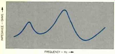
Fig. 1--Conventional plot of the magnitude of impedance as a function of frequency.
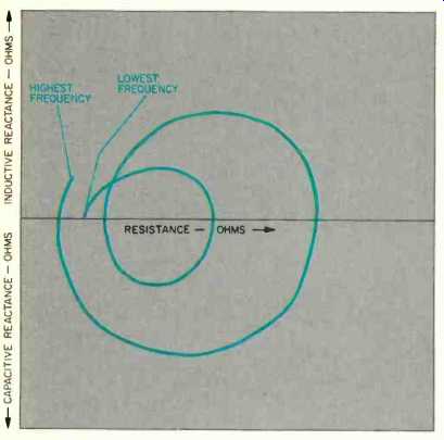
Fig. 2--The same speaker as in Fig. 1, but now plotted as a complex impedance
as a function of frequency.
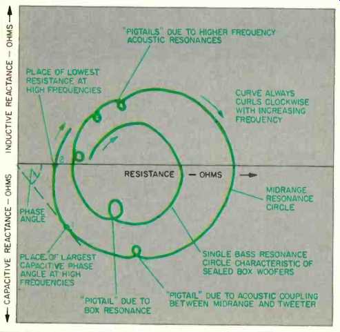
Fig. 3--Some of the things to look for in a complex impedance.
The complex impedance plot looks like a string which has been dropped on the paper. In a sense it is a string, a string that traces out the impedance we encounter as we progress through the frequency range.
The string always curls clockwise as we progress upward in frequency. The plot looks like, and is, circles on circles. The circle form is a fundamental expression of energy exchange. There will be one complete circle component for each condition of energy resonance. As an electromechanical device, the loudspeaker will have a number of impedance resonance modes.
Woofers show fundamental signatures on this plot. A sealed woofer will have one bass resonance circle, while most vented woofers will have two.
This can reveal information that even the loudspeaker designer was not aware of. For example, a poorly sealed system may have an air leak. Can't fool Mother Nature; the leak will show as an unexpected circle in this measurement. This is a clue to degraded low frequency performance.
Another situation is the distinction between the nice, simple resonance, generally assumed by designers, and the real world. We know the woofer pushes air and makes sound; the sides of the box also push air and make sound, but that's not what the designer had in mind. The effect of box sound is often visible in our review data as a deformation of the otherwise perfectly circular form of simple bass resonance (see Fig. 3). This will also show up as an apparent clockwise rotation about the origin of the plot by the bass resonance circle.
If the lower bass-resonance frequency in a vented system falls much below 15 Hz, watch out. Subsonic audio components, such as those due to record warp and tonearm resonance, might cause unnecessarily large cone excursions at high sound levels. The sonic effect can be pure mud. It is not the loudspeaker's fault as much as it is the program material's. When it occurs, use a rumble filter to cut out subsonic components.
Sometimes separate drivers in a system will talk to each other, like chatty neighbors over a backyard fence.
Acoustic coupling between drivers is always unavoidable, but if improper crossover design allows two or more drivers to carry on simultaneous conversations in the same frequency range, each driver will hear the other talking and show it as a change in impedance. Small extra loops, which look like pigtails added to the string, are telltale clues to this inter-speaker chitchat.
Progressing upward in frequency, the string shows wanted, as well as unwanted, resonances. Space does not permit complete discussion of everything to look for, but one condition can cause amplifier distress. Most constant-voltage amplifiers drive resistors and inductive loads better than they do capacitive loads, particularly at high frequencies. Figure 3 illustrates what to watch for. At high frequencies, where slew rate becomes important, point 1 on curve A is a harder load to drive than point 2 because the current demand leads the voltage being controlled. This means that the amplifier must deliver its peak current demand prior to the time that the voltage waveform reaches its peak value. The worst case is reached when the peak current occurs at the same time the voltage is passing through its maximum rate of change. This would be a purely capacitive load, represented by a complex impedance point on the negative vertical axis. Under this condition, the power amplifier must deliver maximum current when there is a very low instantaneous voltage on the speaker but the highest waveform slew rate. (The term slew, or slue, means to turn or swing around. Early gun-control servomechanisms were required to slew the gun mounts at high rates to follow precise pointing signals from the fire-control radars. There was a maximum swinging rate, or slew rate, which the amplifiers could follow and maintain complete control of the gun mount. Thus, by devious pedigree, the term slew rate came to mean maximum voltage rate which an amplifier could deliver.) The smaller the net impedance at point 1, the harder the drive requirements. If this condition prevails in the upper registers, brass, strings, and vocals can go harsh at high sound levels.
A loudspeaker makes a very good microphone. In the case of the conventional moving-coil loudspeaker system, every sound in your listening room is picked up by the loudspeaker. The sounds are converted to current, which the loudspeaker tries to drive back into the power amplifier. It does this even when the power amplifier is supplying an audio program. If you could hook up a sensitive ammeter to the loudspeaker wires, and could "buck out" the simultaneous audio program, it would be possible to measure sound in the room at the same time that music was being played. This is not a ridiculous idea and can actually be accomplished under special conditions.
Of course, the usual situation is that the sound in the room is principally caused by the loudspeaker itself. In that case, the "microphone" pickup current is related to the "program" current in the speaker wires. When we apply a voltage to the terminals, and measure the resultant current that flows, we are measuring current passing from the amplifier into the loudspeaker as well as current passing back to the amplifier. If we pause for a moment and think about it, that is exactly the type of information contained in the impedance measurement.
Therefore, loudspeaker impedance contains a great deal more information than is assumed by the manufacturer when he states "... this is an 8-ohm system." Some of the information can be downright embarrassing to the manufacturer, such as when it shows that his "sealed" box has an unwanted leak, or when it shows that the midrange and tweeter acoustically talk to each other at the same time over a broad band of frequencies, or when it shows that his "solid" walnut-covered enclosure resonates like a bass drum at some unwanted frequency.
Some of the information tells us about the acoustic coupling between the loudspeaker and the room, and how good (or bad) the acoustic match may be. Because of that, I try never to measure impedance with the speaker facing a hard, reflecting surface. If I have any suspicion that some of the squiggles on the complex impedance plot are caused by the measuring room, I will move the loudspeaker and repeat the measurement.
Because present-day loudspeakers are designed to produce sound pressure based upon constant voltage applied to the speaker terminals, it would make sense to measure the amount of current that is drawn at this rated voltage. This is just the inverse of impedance. Whereas impedance is a measure of the voltage drop produced by a fixed amount of current, admittance is a measure of the current drawn when a fixed voltage is applied. In the simple case of the loudspeaker, admittance is the inverse of impedance.
Personally, I would prefer to measure the complex admittance of a loudspeaker, since this tells me how much current is drawn if I put, say, 4V across the speaker terminals at 1 kHz. Speaker current is then the product of a signal voltage times a factor called admittance. Instead, I must remember that speaker current is equal to signal voltage divided by the factor called impedance. I am lazy, and it is mentally much easier for me to multiply than to divide. But over half a century of tradition has been developed around the concept of loudspeaker impedance, and I grudgingly bow to this tradition in quantifying the driving-point properties of loudspeakers. Besides, that is the property cited by the manufacturer when he sells you the product, and we are trying to see how well he meets his commitment to you.
Admittance, like impedance, must have two parts, and these parts are related to dissipation and storage of energy. The part related to dissipation is called conductance, and the part related to storage is called susceptance. The units of measure for these parts is the inverse of the units of measure for impedance. A 1-ohm resistance corresponds to a 1-siemens (we used to call it "mho," for ohm spelled backward) conductance, and an 8 ohm resistance corresponds to a '/8 siemens conductance.
In defense of the impedance measurement, impedances in series are added. Thus, a 1/2-ohm speaker wire adds 1/2 ohm to the impedance seen by the amplifier. And there is, technically, nothing contained in an impedance measurement that is not contained in an admittance measurement, and vice versa. The reason I bring up the subject of admittance is to describe another aspect of our loudspeaker measurements in Audio.
It is no secret that I have tried to present a format of data, in the guise of the complex impedance plot, which can be of great value in the design of better power amplifiers. Loudspeakers are not resistors, and those who design power amplifiers to drive resistor loads exclusively are simply fooling themselves. Furthermore, no two different loudspeaker designs have the same impedance (or admittance) properties, and as loudspeaker designs evolve over the years, the type of loads which they present to amplifiers also evolves.
The output stages of the amplifier, which must take it on the chin when driving a loudspeaker, have their safe and their unsafe operating regions. It is no great difficulty for a power amplifier designer to produce a plot of exactly what regions of load current are safe under various signal conditions. When I say "safe," I am referring not only to whether or not the transistor, FET or whatever will blow up, but how the feedback margin and slew rate of the amplifier are affected.
Don't think, for example, that the feedback factor of a power amplifier is not affected by the load which it drives; it is. Consider, for example, what happens to the feedback signal if you short-circuit the output terminals; those amplifiers whose feedback is obtained from the output terminals are then operating in an open-loop condition. That amplifier which operates essentially without distortion into a 4-ohm resistor may have substantially altered distortion properties when driving a 4-ohm complex load.
If the amplifier designer plots the value of allowed complex impedance versus drive level, drive duration, and feedback properties, including internal slew-rate limitations, he need only overlay a plastic transparency of Audio's impedance plot to see whether his amplifier will cut the mustard with that particular speaker. Furthermore, an overlay of the corresponding complex admittance diagram will indicate such niceties as peak instantaneous current under conditions of XYZ speaker cable interconnect.
The complex impedance (and admittance) plot is sufficiently difficult to perform that the vast majority of loudspeaker manufacturers do not, themselves, know what the complex load properties of their products are. Therefore, Audio publishes these measurements. After many years of such published measurements, I believe that there can be no excuse for a power amplifier designer who produces a product optimized for a mythical load resistor. One intent of the complex impedance measurement is to archive data which can allow for better audio amplifier design, and thus the importance of the measurement extends far beyond the particular review in which it is published.
As a final consideration, loudspeakers are notoriously nonlinear in their electromechanical properties. Impedance (and admittance) is a function not only of instantaneous drive level, but of the immediate past history of signal which has been applied to the speaker. They are non-Markovian in their signal-handling properties. (A Markov process is one in which the immediate present is strictly dependent only upon the immediate past and statistically dependent upon the more distant past. If the value of a signal from the distant past has an effect on the manner in which the present value is to be processed, other than an additive memory contribution, then the processing is non-Markovian.) There are recoverable hysteretic effects in the drive properties which modify the impedance at a particular drive level. And there are nonlinear suspension properties which can cause a woofer cone to drift in and out of its average no-signal position under special combinations of excitation. These all modify the nature of the load which the loudspeaker presents to a power amplifier.
Due to space limitations, the Audio measurements are those of the small signal linear impedance. I watch for nonlinear drive properties during the higher power distortion measurements which I also perform on the loudspeaker. If I spot problems, I comment on them in the narrative part of the review.
Let me wrap up this little discussion by commenting on something that is true of all of the measurements in Audio's reviews. The measurements are technically difficult to perform and require highly specialized equipment.
But they are world-class measurements, not simply something that happens to be available in a particular piece of commercial test equipment.
The data is presented in such a way as to be of value to readers at several levels of audio involvement. First, a narrative is provided for those who could not care less about highly technical matters and only want to know what to watch out for in nontechnical terms. These narratives also include more technical matters that are discussed in relation to the measured data which is supplied as plots. And, finally, the technical content of the measurements is sufficient to be of value to professionals who design the products which you listen to. They, too, read Audio magazine.
(adapted from Audio magazine, June 1984)
Also see: Link | --Plane Facts About Flat Speakers by Kenneth L. Kantor (Aug. 1987)
History of Magnetic Recording—part 2 (Sept. 1984)
= = = =