
above: shown are Philips RM532, LWE 15, and Andante 3A speakers
by George W. Tillett
A BIG PROBLEM loudspeaker designers face today is the difficulty of producing good bass response from a small system. As the enclosure size decreases, the air inside becomes stiffer, which tends to restrict cone motion and force the system resonance higher. For example, an 8-in. speaker with a free-air resonance of 25 Hz might have a resonance as high as 130 Hz in a one cubic foot closed box.
This generally means that the low frequencies will be distorted, and what bass is produced will be colored. System resonance is determined by the cone diameter, magnetic field, moving mass, suspension, and the stiffness of the air spring Thus, the designer can either trade efficiency for bass by using some kind of mass loading, he can use a smaller cone, which might increase the intermodulation distortion (and probably cost more due to the increased magnet size), or he can opt for a vent. This vent can take the form of a tube or duct, but it too must be very carefully designed or it can make matters worse! Alternatively the designer could put the loudspeaker inside the amplifier feedback loop where the distortion could be reduced and the resonances controlled. This concept is called Motional Feed Back, or MFB.
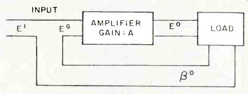
Fig. 1--Block diagram of a system with negative feedback.
Most engineers believe that when negative feedback was found to improve the performance of amplifiers, loudspeaker designers then began to wonder how the same principle could be applied to reduce the distortion produced by loudspeakers. One might think so, since amplifier feedback was invented a long time ago, but as Josh Billings would say, it just ain't so. Although Black and Blumlein were working on amplifier feedback in 1934 (1), Hanna had filed a patent for a system of servo (motional feedback) to control the response of a balanced armature speaker some 10 years earlier (2), During the next 20 years, many articles on motional feedback were published, and the problems were well summarized by Olson (3) in 1940.
In simple terms, negative feedback means that a portion of the output of an amplifier is fed back in opposite phase, thus reducing the overall gain as well as canceling some of the non-linearity (distortion). Figure 1 shows a block diagram of an amplifier with a feedback loop. The gain of the amplifier is A, thus:
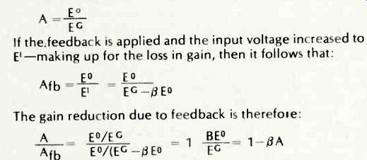
The quantity 1-ßA is called the feedback factor and is usually expressed in dB. Thus, to say an amplifier has 20 dB of feedback means that the feedback loop has reduced the gain by 20 dB or a factor of 10. If the amplifier has been well designed, then the distortion will have been reduced by a similar amount.
The question is, how to put the loudspeaker inside the feedback loop? Well, there are three methods commonly used. The first uses a separate voice coil to produce the feedback voltage (or current); the second uses a transducer to pick up the output signal, and the last takes a feedback "error" signal from a bridge or other network connected to the loudspeaker.
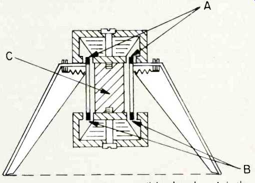
Fig. 2--The Gogny twin voice coil loudspeaker. A is the driven coil and B
is the pickup coil. C is made of non-magnetic material and serves only as a
mounting piece.
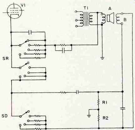
Fig. 3--MFB circuit used in the Matsushita amplifier. A is the driven coil,
B is the pickup coil which provides the feedback signal. T1 is the amplifier
output transformer.
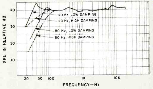
Fig. 4--System resonance and damping in the Matsushita amplifier. Two resonant
frequencies, 80 Hz and 40 Hz are shown, each with high and low damping.
Applications of MFB
Figure 2 shows a loudspeaker with twin voice coils developed by Gogny in France, patented in 1954. As might be expected, there are a number of problems associated with this kind of construction. The pickup assembly must be kept small to avoid irregularities in the cone radiation, and the electrical coupling between the coils must be kept at minimum. The Gogny speaker had a very short voice coil, measuring only 8 mm (1/3in.) with a diameter of 1 1/2 in. The cone size was 12 in. and the servo control could only function up to the frequencies at which cone breakup occurred. In this case, the crossover point was 800 Hz, and the cone acted more or less like a piston below that frequency. I heard this hybrid servo system several times at the Gogny plant in Paris and was most impressed with the clean bass and overall clarity.
About the time Gogny was carrying out his experiments, or possibly even earlier, Naraji Sakamoto, of the giant Matshushita company in Japan, also evolved a practical double voice coil loudspeaker. The driven coil was about 1 1/2 inches in diameter and the pickup coil was one inch in diameter.
Cone size was 8-in. and, as in the Gogny system, feedback was used only up to 800 Hz. Conventional crossovers were employed with a 3-in. midrange unit plus a 2-in horn tweeter. The enclosure size was 0.83 cubic ft., and Fig. 3 shows the basic circuit used in the companion amplifier. T1 is the amplifier output transformer, and signals from pickup coil B are taken via two paths to switch SD, with another loop taken from driven coil A. Note the two resistors, R1 and R2, giving a combination of negative and positive feedback, an arrangement often used in amplifiers to obtain zero output impedance in the days when this was thought desirable. The feedback loops are taken to the cathode of a pre-driver tube and control SD will affect the damping, while twin control SB changes the speaker system resonance as shown in Fig. 4.
Two extremes are shown, 40 and 80 Hz system resonances, each with high, and with low damping. Although Sakamoto seems to emphasize the importance of resonance control and critical damping to get good bass from a small enclosure, the MFB arrangement also reduces distortion, as can be seen in Fig. 5. Here an 8-in. speaker with MFB is compared to a similar unit without feedback, in terms of second and third harmonic distortion.
The same loudspeaker was used with several other amplifier systems, but the MFB circuitry was simpler, although at least two had bass-lift controls in the feedback loop.
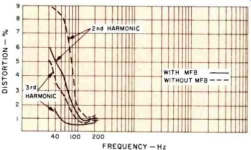
Fig. 5--Second and third harmonic distortion of Matsushita speaker, with and
without MFB.
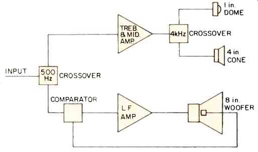
Fig. 6--Block diagram of the Philips RH-532.
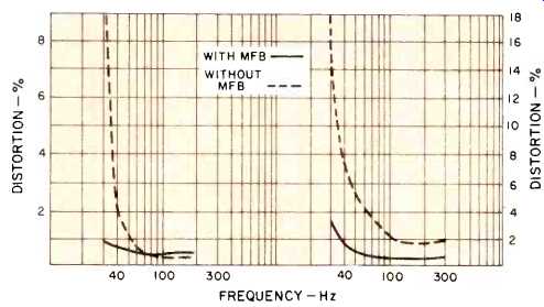
Fig. 7--Distortion of the Philips 8-in. cone (left) and distortion of the 3A
speaker (right), each shown with and with out MFB.
Feedback Via Piezo Material
Now for a look at the transducer method (4) of MFB-the most successful being the Philips system developed by Klaasen and de Koning (5) about 7 years ago in Holland. The present system (reviewed in our April, 1975 issue) consists of three loudspeakers all housed in a small enclosure measuring only 15 in. H. X 11 in. W. X 8 in. D. The bass speaker has an 8-in. cone, and it crosses over to a 5-in. midrange unit at 500 Hz, with a 1-in. dome taking over at 4 kHz. These speakers occupy only 550 cubic inches, while the rest of the space is taken up by a 40-watt low-frequency amplifier plus a 20 watt unit for the treble and midrange. Truly a case of mul-turn in parvo! The transducer used for feedback is really an accelerometer-a disc of piezo-electric material mounted on the loudspeaker voice coil together with a tiny preamplifier. The voltage generated is proportional to the mechanical movements of the cone, which are compared to the input signal by the comparator as shown in Fig. 6. The two signals are 180 degrees out of phase and distortion is reduced considerably, as shown in Fig. 7. This acceleration feedback effectively increases the apparent mass of the moving system so the resonance is brought down. The system resonance is lowered by the use of MFB in this case to 35 Hz. This is a dramatic improvement, for without MFB it would increase to 75 Hz!
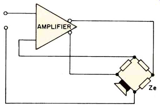
Fig. 8--Typical bridge MFB circuit. Ze is equivalent to the impedance of the
speaker in blocked state.
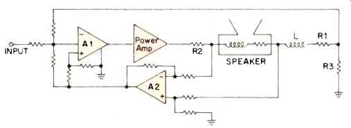
Fig. 9--MFB circuit developed by NASA. L1, R1, and R3 form the sensing network.
The third system of MFB is sometimes called velocity feedback, as it makes use of the back emf generated by the speaker voice coil due to its motion in the magnetic field. In other words, the speaker acts as a microphone, and at resonant frequencies, where the cone movement is larger than the applied signal, an error signal is generated. This has to be separated from the applied signal and there are several ways to do this. A bridge circuit is often used (6) and Fig. 8 shows an example. Connected in series with the loudspeaker is network Ze whose phase angle is equal to the impedance of the loudspeaker in the blocked state. The difference voltage is then applied as feedback (7,8). In a more elaborate version developed by the Ames Research Center of NASA (Fig. 9), a sensing network is formed by L, R1, and R3; the speaker voice coil is shown as a lumped inductance with internal resistance.
Velocity MFB systems are also used by LWE, the French company 3A, and the Belgian firm Servo-Sound. The last-named company also uses a non-linear-feedback arrangement to boost the bass at low listening levels. The French firm calls their system Acoustic Pressure Feedback. It has a 10-in. bass unit with a 4-in. midrange and a 2-in. horn tweeter. The built-in amplifier has an output of 125 watts and is housed in the speaker enclosure. The system measures a mere 18-in. H. X 12-in. W. X 7.5-in. D. A bridge circuit is used to derive the feedback voltage. At 30 Hz, the bass cone moves nearly one-half inch with input of only five watts sine-wave power. The distortion characteristics are given in Fig. 7. The bass unit crosses over to the 4-in. unit at 400 Hz, and the crossovers are built-in. Provision is made for a separate 20-watt amplifier for the treble and midrange. These 3A systems are now available in Canada and will be sold here in the near future.
The LWE loudspeaker systems were designed by L.W. Erath and are now marketed by CM Laboratories, Inc. Unlike the 3A system, the LWE servo-control extends over the entire audio spectrum, with one element in the sensing network variable to permit some modification of the bass response. This variable element is called "Room Gain Control," and it has five switched positions. The largest system in the LWE line uses a 15-in. bass speaker, a 6-in. midrange, and two tweeters, while the smallest, Model 10, is a bookshelf system with a 10-in. woofer and a 2-in. tweeter. All these systems are available separately but if they are not used with a CM amplifier the connections inside the amplifier would have to be made by a technician.
Summary With the growing popularity of quadraphonic sound and the consequent emphasis on small loudspeaker systems, MFB would seem to provide some of the answers to the inherent space problems. I am sure we will see more high quality compact systems with built-in amplifiers with MFB in the not too distant future. If only an MFB system could be devised that would provide complete room correction too...!
References
1. H.S. Black, "Stabilized Feedback Amplifiers," Electronic Engineering Handbook, 1934.
2. C.R. Hanna (Westinghouse), U.S. Pat. 1,645,282 (filed 1924), granted 11 Oct. 1927.
3. H.F. Olson, Acoustical Engineering, D. Van Nostrand, Princeton, N.J., 1940.
4. H.W. Holdaway, "Design of Velocity Feedback Transducers," Transactions IRE, Sept. 1963.
5. J.A. Klaasen and S.H. de Koning, "Motional Feedback with Loudspeakers," Philips Technical Review, 1968, No. 5. Also E.R. Hanson, "A Motional Feedback Speaker System," AES Preprint No. 924.
6. D.T.N. Williamson, "More Views on Loudspeaker Damping, Wireless World, Dec. 1947.
7. H.H. Lowell, "Motional Feedback," Electronics, Dec. 1951.
8. E. de Boer, "Theory of Motional Feedback," Transactions IRE, Jan. 1961.
(Source: Audio magazine, Aug. 1975)
Also see: A.N. Thiele--Sage of Vented Speakers (Aug. 1975)
= = = =