
by Ray Newman*
[*Senior Systems Engineer, Electro-Voice, Inc. Buchanan, Michigan ]
RECENTLY A SIGNIFICANT and elegantly-written article describing the nature of vented speaker boxes was republished in this country (1,2) 10 years after its original publication in Australia (3), A.N. Thiele's "Loudspeakers In Vented Boxes." I strongly believe this article is an important milestone in the literature on high-quality sound reproduction, and that it deserves to be shared with a wide spectrum of readers. It has already stirred active interest as shown by several notes and letters in the AES Journal (4,5,6,7) and in recent AES convention papers (8,9). In his article Thiele investigates the behavior of vented box speaker systems by analyzing their equivalent circuits as high-pass filters. Using techniques of electrical network analysis, he arrives at a remarkable tabulation involving not one, but 28 ordered ways of creating a vented-box speaker system! The discussion ranges to such matters as the specifics of designing the speaker box, measurement of required loudspeaker characteristics for proper design, and some especially significant discussion regarding loudspeaker efficiency and cone excursion as they relate to different system types. The details of some of these matters together with their implications will be pursued in this article. It should be understood from the, outset that only the mid-to low-frequency part of the system, roughly below the frequency at which the cone's circumference equals one wavelength is being dealt with. This in no way detracts from the importance of Thiele's article, as this region is a most demanding one indeed and generally dictates the size and performance format of the complete system.
The following important implications of the generalized vented-box information presented by Thiele are listed here as an early broad summary:
1. Considering the four interrelated matters of low-frequency limit (the 3 dB-down point), usable cone diameter, maximum cone excursion above the low frequency limit, and acoustic power output, the nature of many types of vented systems as compared to sealed systems can be summarized as shown in Table I.
2. A simple but elegant relationship between system efficiency, low frequency limit, box volume, and one parameter pertaining to the speaker mechanism alone is also described by Thiele. This relationship is valid for both vented and closed systems, and although Thiele's table of 28 alignments indicates that many comparisons are possible (depending on the type of vented system), one of the more useful alignment types (Thiele's fourth-order Butterworth alignment) yields the comparisons shown in Table II between a vented and a closed-box system possessing flat response. Again this implication, stated in three different ways, is a powerful and useful concept.
3. Thiele's tabulation (Table IV) of 28 ways of creating a vented system is the most interesting and useful information of all. Presented in concise format are a large palate of possibilities for creating correctly-tailored speaker-box systems.
Each of these possibilities or, as Thiele refers to them, alignments has its own set of interesting characteristics. As examples:
(a) Some alignments describe how to make systems with the low-frequency limit higher than box tuning and the speaker's free-air resonance frequency.
(b) Other alignments describe systems with the low-frequency limit lower than box tuning and the speaker's free-air resonance frequency.
(c) Still other alignments are realized by using auxiliary electrical filters or equalizers. These illustrate ways of trading off box volume for system efficiency in the lower part of the system's operating range.
The possibilities of the alignment table are fascinating from the standpoint of system design, because they permit a logical and systematized approach in creating a vented speaker system. Further, they permit the system to take many different forms in terms of performance characteristics, box size, and speaker parameters to suit particular design goals. The Alignment Table (Table IV) changes vented box design from something akin to splashing around in the Dismal Swamp, to having at least a canoe and a compass.
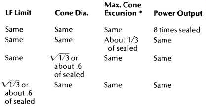
Table I--Relationships of Parameters of Sealed and Vented Systems.
* Considering only the range above low frequency limit, maximum excursion occurs at this limit for a sealed system and at 1.45 times this limit for Butterworth-type (see text explanation) vented systems.
The Alignment Table
The high point of Thiele's presentation is the table of alignments-methods of properly coordinating the box and speaker for a specific type of system response (12). Table IV, presented here, is somewhat simplified from Thiele's table.
The Alignment Details column includes the name of the filter that describes the response of the system. QB3stands for quasi-Butterworth third-order filters, B for Butterworth filters, and C for Chebyshev filters. The Butterworth filters are characterized by flat-frequency response, and the Chebyshev filters are characterized by small ripples in the response. Note, however, that none of the Chebyshev responses in the Table have ripples exceeding 1.8 dB. Figure 1 illustrates the nature of these two types of response.
The subscripts may be thought of as describing the rate of response falloff below fa, with the fourth order (subscript 4) falling off at 24 dB/octave with decreasing frequency, the fifth order at 30 dB/octave, and the sixth order at 36 dB/octave. Note that all the alignments have basic 24 dB/octave falloff rates due to the mechano-acoustic nature of the beast, and that the more rapid falloffs are a by-product of the electrical filters or auxiliary circuits required (i.e., additional electrical rolloffs of 6 dB/octave and 12 dB/octave for fifth- and sixth-order responses, respectively). Additional table notations are as follows:
f3 = the 3-dB-down point on the response curve;
fs = the speaker's free-air resonance frequency;
fb = the frequency at which the box is tuned (a function of box volume, vent area, and length, not of the speaker mechanism);
Cas = the acoustic compliance of the cone suspension system (crudely, how "loose" the suspension is); Cab = the acoustic compliance of the volume of air in the box (Ccb = NVb, where N is a constant dependent on the measurement system used, and Vb is box volume), and Qt = the speaker's "Q" when connected to the driving amplifier. (This may be thought of as how far down the speaker's response is at free-air resonance relative to its mid-band response in a very large baffle i.e. Qt = 0.5 means that the response is down 6 dB at resonance.)

Fig. 1--Nature of Butterworth and Chebyshev filter responses compared.
With the above definitions in mind, several observations may be made. Note that only three pieces of information (fs, Cas, and Qt) are needed to completely describe the nature of the speaker mechanism alone (assuming amplifiers with high damping factors) to create a system, and that the complete system calls for three ratios, involving box characteristics, low frequency response limit, and speaker characteristics plus the speaker's Qt to be at specified values for a specific alignment. For a speaker designer, this requires the selection of a specific alignment (because of some desired characteristics it possesses), usually coupled with a selection of low frequency limit (f3), box size, and speaker diameter, and then careful manipulation of the three speaker characteristics (fs, Cas and Qt) to satisfy the requirements of the table. In practice, this is a rather complicated matter as the initial selection of alignment type, f3, box size, and speaker diameter involve dragging in many external considerations regarding the amount of power the system must radiate, distortion levels, where the system will be used, etc., which are beyond the scope of this article.
As the table of alignments appeared not to be generally known in the U.S. until recently, many, if not most, available unmounted speakers intended for vented boxes have somewhat random characteristics not necessarily tied to specific table alignments. For such random characteristic speakers the moderately large number of table alignments provides the designer a better chance of finding a reasonable (and hopefully usable) alignment for his speaker. Let us instead, however, consider the table from the viewpoint of a thoughtful designer of speakers who has knowledge of the table's existence prior to creating his speakers.
The first item to note in classifying the alignments in the table is that the first nine alignments do not require auxiliary electrical circuitry or equalization, unlike the remaining 19.
Of these first 9, numbers 1 thru 4 are characterized by having the system's low frequency limit (f3) higher than both the speaker's free air resonance frequency (fs) and the box tuning frequency (fb). (This appears in the table as entries showing f:,/fs greater than 1, and f3/fb greater than 1, respectively.) In the case of the first four alignments, the table also implies a speaker considerably more compliant than the air volume in the box (Cas/Cab considerably greater than 1) and small Qt's if you please (Qt's less than .303), which usually implies large magnets. The remaining unequalized alignments (5 thru 9) indicate low-frequency limits at or below the unmounted speaker's free spare resonance (f3/fs is 1 or less). Also implied here are box tunings at or above the low-frequency limit (f3/ fb is 1 or less), stiffer speakers relative to the box air volume stiffness (Cas/Cab of 1.4 to .485), and more generous Qt's (.383 to .557). In alignments 5 through 9, the greatest novelty is their ability to maintain output below the speaker's resonance frequency, although often fairly large boxes are required to do this and rapidly rising cone excursion in the region of f3 to fb is a by-product. Some interesting possibilities are presented by these 9 unequalized alignments although I suspect that, like as not, most designers of systems would settle on alignment 5 or one near it.
The remaining alignments (10 thru 28) all require an auxiliary filter. Alignments 10 through 14 can be realized with passive electrical networks, as the networks here have the function of removing a natural low-frequency rise from the response; in other words they "de-hump" the extreme low end of the system's response. Figure 2 illustrates the nature of these responses.
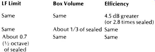
Table II--Relationships of low-frequency limit, box size, and efficiency between
sealed and vented systems.
LF Limit Box Volume Efficiency

Fig. 2--Nature of response of alignments 10 through 14 before and after addition
of the required auxiliary filters.

Fig. 3--Nature of response of alignments 15 through 19 before and after addition
of the required auxiliary filters.

Fig. 4--Nature of the response of alignments 20 through 25 before and after
addition of the required auxiliary filters.
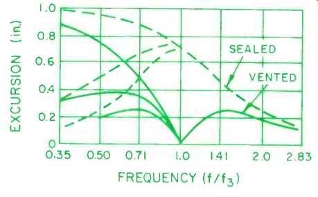
Fig. 5-Cone excursion as a function of frequency for Butterworth-aligned vented
systems and for sealed systems, with and without filters (after Thiele).
Alignments 15 through 19 can best be realized with active electrical networks. The networks here are required to lift up the extreme low end, as shown in Fig. 3. These alignments have the interesting tradeoff of box volume for some efficiency loss (with flat response restored by the equalizer) at the extreme low end of the system's range. These alignments can permit smallish boxes to have rather low cutoffs (note the moderately large values of Cas/Cab). This may be seen by noting the similarities between alignments 4 (an un equalized alignment) and 15 (requiring a lift equalizer).
Note here that the speaker Qt values are about the same (around 0.3) and the Cas/Cab values are about the same (around 3.0). This would permit taking the same speaker in the same box and altering the vent or box tuning to obtain f/fs = 1.45 for alignment 4, or to 1.0 for alignment 15 (with the 6-dB equalization lift for alignment 15). Thus, by using the equalized system, it is possible to decrease the low-frequency limit by a factor of 1.0/1.45, at the expense of a moderate amount of efficiency loss in the extreme bass--fascinating! The odds against coming up with a correct number 15 alignment by splashing around in the swamp of empirical cut and try without Thiele as a guide are vast.
Yet another group of alignments, which can probably be best realized thru the aid of active filters, are numbers 20 thru 25. In these cases, the filters are required to restore an unequalized system-response characteristic that progressively begins to resemble a dip between the low-frequency limit of the system and its mid-frequency response as alignment number 25 is approached. A rough idea as to what is being done is illustrated in Fig. 4.
In general, alignments 20 through 25 progressively tend toward boxes with large air compliance compared to speaker suspension compliance (Cas/Cab is 1 or less), which often implies large boxes with the reward being a low frequency limit usually substantially below the speaker's free air resonance, (Alignment 25 has its -3 dB point at about 0.4 fs-with a moderate filter boost of only 6 dB. Note that the electrical filters employed with these alignments (as well as those employed with the other equalized alignments discussed) progressively cut off electrical input to the speaker system below its low-frequency limit (f3), which is an aid in reducing low-frequency cone excursion in the region where such excursion gives little fundamental acoustic output (but often appreciable distortion). The conservation of amplifier power below f:, also tends to make up for the increased amp output required for the boost filters used by most of the alignments 15 to 25 in the range above f3. It is difficult to completely sum up this table of alignments as it contains so many unusual possibilities for vented systems with the most interesting physical realizations of these possibilities often lurking within the fs's, fb's, and C's of the tabulation in tantalizing, mind-twisting ways. Some of the gross characteristics of groups of these alignments have been discussed here to illustrate a few of the meanings of the table and pass on the realization of the many possible, often highly sophisticated, ways of dealing with the seemingly simple task of putting a hole in a speaker box.
System Efficiency Relations
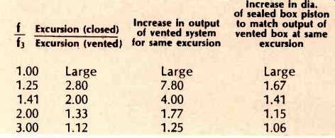
Table III--Comparison of output, Cone Diameters, and Cone Excursions of Vented
Box and Sealed Box Systems under certain conditions.
A highly significant matter which deals with relationships between several system parameters and efficiency is developed by Thiele. As Small points out in his project note on efficiency (13), several writers have realized the significance of this (14) (15) (16), but Thiele appears to have been the first to record it in the literature. Knowledge of the way system parameters affect efficiency is quite important since amplifier power, even now, is not unlimited, and a designer has to contend also with the problem of speaker destruction, especially in trying to reach live performance sound pressure levels. Efficiency describes how much electrical power input is needed for a particular acoustic power output. This power output, coupled with the size and characteristics of the listening environment, are what determines pressure levels in the environment. Currently, when home speaker designers are reaching for ever-smaller boxes and also trying to maintain an adequate low frequency limit, a knowledge of when the absurd is being approached or of ways of obtaining the best return from moderate-size boxes would seem important. Thiele shows how to grasp this situation in a usable manner for both vented and sealed enclosures. The relatively simple expression that helps to do this is (17) which can be restated as:
E = 16 x 10-12 f33 VbK,
Where E is the conversion efficiency presuming radiation is confined by a large flat surface (or radiation into a half space); f3 is the frequency at which the system's output is 3 dB down; Vb is the internal volume of the box (cubic in.). In the case of sealed systems, this presumes that the stiffness of the air in the box is much greater than the stiffness of the loudspeaker mechanism, and K is a factor dependent on specific system type--usually 1 to 2 for sealed-box systems, and 3 to 4 for vented, un equalized systems.
This expression is indicative of the efficiency of a system at low frequencies (wavelength greater than speaker circumference), but if good total system design is followed, the efficiency over most of the audible range probably should be less than 3 to 6 dB below this level.
Of interest on first inspection is the powerful effect of f:,, which is raised to the third power. Thus, cutting f:, in half means reducing efficiency by 8 times, or 9 dB. Of lesser influence is the effect of Vb, with the implication that every time box size is halved, so is efficiency (i.e., 3 dB). As noted in the definition, the K factor is between 1 and 2 for most sealed-box systems, and between 3 and 4 for most simple vented systems, although values of 9 to 18 are possible for some vented systems requiring auxiliary filters.
Small (18) points out that comparison of a common non equalized number 5 alignment with a sealed box can yield the conclusions presented in tabular form at the beginning of this article. Having 4.5 dB of additional efficiency available for the same low-frequency limit and box size can be useful when a designer is working near the limits imposed by very low efficiencies-chiefly very large amplifier requirements and danger of electrical burnout. As home systems often tend to maintain excellent low-frequency performance with the smallest reasonable box size (of even greater interest now, with 4-channel systems), the information in the efficiency equation can be pit to good use by employing vented systems to decrease fa or decrease box size, while maintaining the same efficiency as a closed-box system.
Cone Excursion Considerations
Figure 5 is reproduced from Fig. 10 of Thiele's article (19). Relative cone excursions are illustrated for three cases of sealed-box and three cases of a vented-box of the Butterworth-type alignments. Note the minimum excursion at f/f3 = 1 inherent in the vented system. Cone excursion in realizable systems can be a very small value compared to the higher-frequency excursions at the same output power. It i fascinating to watch the cone become essentially motionless at f:, while high sound levels are produced by the system Peak excursion for the vented system is reached at 1.45 times the low-frequency limit, and decreases as f/f3 continues to increase. In contrast to this, closed-box systems reach their near-maximum excursion values at in-box resonance and show a constant drop with increasing frequency at a given output level.
The differences in the plots below f/f3 = 1 are due to the effects of auxiliary filters being applied in four of the six examples. The particular examples portrayed involve specific, carefully-coordinated, filter-loudspeaker-system combinations chosen for complementary characteristics. The highest excursion curve of a given box type is associated with an unfiltered system, the middle curve requiring use of a first-order filter (6 dB/octave decrease of the electrical in put to the system with decreasing frequency below f/f3 = 1) and the lowest curve requiring a second-order filter (12 dB/octave decrease in system input below f/f3 = 1). Note that low-frequency-cut filters can be applied to any kind of system, but in alignments 10 through 27, the low-cut feature is automatically a part of the required auxiliary filter.
(Alignments 10 to 14 specify first-order filters, while 15 through 27 specify second-order filters.) Thiele believes the input-extinguishing action of the filters below the low-frequency limit of the system is desirable, and reasonably so, since the filter action:
A. Conserves available amplifier power by more nearly restricting its use to the part of the low-frequency spectrum that the speaker system is capable of reproducing well, and
B. Reduces distortion caused by the speaker being driven to what would be (without a filter) its largest excursion in a frequency region where acoustic output is becoming rapidly diminished.
Considering the frequencies above f/f3 = 1, a tabulation is shown in Table III for the ratio of cone excursion of a closed-box system to that of a vented-box system, assuming the same output power is available from each. In one column difference in excursion is tabulated, presuming the same available piston size for both systems. A second column translates this excursion to the increase in power output required to bring the excursion of the vented system up to that of the sealed unit. The third column shows the increase in piston diameter of the sealed-box system necessary to match the output of the vented system if the excursion must stay the same. The last column is especially interesting because it illustrates that as the frequency of a Butterworth-aligned vented box approaches three times the low-frequency limit, the vent ceases to function. At low frequencies, the vented system operates as if it were a sealed system with an ever-growing piston size, until at f/f3 = 1 the equivalent piston has grown to immense size. This explanation is appreciably better than the naive concept that, if both sides of the cone were used through venting, the effective substitute speaker would have twice the area (or 1.41 times the diameter). Actually this equivalent substitute speaker would be this size one-half octave above the low frequency limit, and it would grow rapidly as the limit is approached.
There is a most interesting connection between the substitute speaker matter and the matter of the efficiency increases available through venting. Together these matters imply that f, can be pushed lower through venting, or box size further reduced without running out of excursion and/or pushing efficiency into a problem area, if one is satisfied to deal with the excursions presented by current sealed-box systems. Venting also has something to offer if one is concerned about reducing excursion at a given level of size and frequency bandwidth in order to further reduce forms of excursion-related distortion.
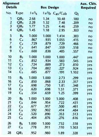
Table IV--Summary of Vented-Box Alignments, after Theile.
Closing Remarks
I have tried to deal with some selected topics from a most elegant and pertinent article in the literature on sound reproduction apparatus. The highlight of Thiele's presentation s the tabulation of 28 ways of designing a vented-box system and doing it properly every time. Topics dealing with efficiency and excursion were singled out as having special importance in discussing what in vented systems is different and significant from the more normal sealed-box type of direct radiator system. Cone excursion is important, as only so much is available and many forms of distortion are associated with it, but it is the connection between required acoustic output levels and the movement of the speaker cone. Efficiency is also significant as it is the connection between required acoustic output levels and the movement of the speaker cone. Efficiency is also significant as it is the connection between acoustic output and electrical input requirements and intimately involves the effects of box size, low frequency system limits, and system type.
The vented system is certainly not new, but it is a format often handled at less than full potential when chosen. To some extent, this may be a reflection of its relative complexity of design and operation and also a need for more information on what it can do and how to make it "do" properly. Thiele's article is certainly a most definitive statement in these respects.
Thiele's work has provided the theoretical groundwork for at least two commercially-available loudspeaker systems in recent years: Interface: A and Sentry Ill, both manufactured by Electro-Voice, Inc. Thiele's paper also was the basis, by way of Small, for a construction project by Messrs. Lampton, Chase, and De Vries in the December, 1973, and August, 1974, issues of this magazine.
References
(1) Thiele, A.N.; "Loudspeakers in Vented Boxes: Part I," Journal of the Audio Engineering Society, Vol. 19, No. 5, May, 1971, pp. 382-392.
(2) Thiele, A.N.; "Loudspeakers in Vented Boxes: Part II," J.A.E.S., Vol. 19, No. 6, June 1971, pp. 471-483.
(3) Thiele, A.N.; "Loudspeakers in Vented Boxes," Proceedings of the IRE Australia, Vol. 22, Aug. 1961, pp. 487-508.
(4) Ashley, J.R.; Postscript to "Loudspeakers in Vented Boxes," J.A.E.S., Vol. 19, No. 6, June 1971, p. 516.
(5) Small, R.H.; "Efficiency of Direct-Radiator Loudspeaker Systems," J.A.E.S., Vol. 19, No. 10, Nov. 1971, pp. 862863.
(6) Ashley, J.R.; "Efficiency Does Not Depend on Cone Area," J.A.E.S., Vol. 19, No. 10, Nov. 1971, pp. 863-865.
(7) Small, R.H.; "Simplified Loudspeaker Measurements at Low Frequencies," J.A.E.S., Vol. 20, No. 1, Jan./Feb. 1972, pp. 28-33.
(8) Keele, D.B.; Jr., "The Vented Loudspeaker: A Restatement," J.A.E.S., Vol. 21, No. 4, May, 1973, pp. 246-255.
(9) Newman, R. J., "A Loudspeaker System Design Utilizing a Sixth-Order Butterworth Response Characteristic," J.A.E.S., Vol. 21, No. 6, July/August, 1973, pp. 450-456.
(10) Thiele, A.N.; "Loudspeakers in Vented Boxes: Part II," J.A.E.S., See equation #77, p. 472.
(11) Small, R.H.; Op. cit. 5, above.
(12) Thiele, A.N.; "Loudspeakers in Vented Boxes: Part I," J.A.E.S., See Table I, p. 388.
(13) Small, R.H.; Op. cit. 5, above.
(14) Jordan, E.J.; "Loudspeaker Enclosures," Wireless World, Vol. 76, No. 1423, Jan. 1971, pp. 2-6.
(15) Kloss, H.; "Loudspeaker Design,", Audio, Vol. 55, No. 3, March 1971, pp. 30-32, 56.
(16) Finegan, J.D.; "The Inter-Relationship of Cabinet Volume, Low Frequency Resonance, and Efficiency for Acoustic Suspension Systems," presented May 5, 1970, 38th Convention of the AES, Los Angeles.
(17) Thiele, A.N.; Op. cit. 10, above.
(18) Small, R.H.; Op. cit. 5, above.
(19) Thiele, A.N.; "Loudspeakers in Vented Boxes: Part I," J.A.E.S., (See Fig. 10 and equations (81) and (84), pp. 472 and 473).
(Source: Audio magazine, Aug. 1975)
Also see: Motional Feedback in Loudspeakers (Aug. 1975)
Construct a Dynamic Noise Filter (June 1975)
= = = =