W. J. J. Hoge [CTS of Paducah, Inc., Paducah, KY 42001]
Recent studies have shown that most music has little pro gram content below 40 Hz. The open E string of a bass (acoustic or electric) produces a note with a fundamental of 41.2 Hz, the low A on a piano has a fundamental of 27.5 Hz, and an organ with a 32-ft. pipe produces a low C with a 16.4 Hz component. However, the fundamentals of the notes produced by all of these instruments are very low in amplitude compared to the harmonics. Tests have shown that a loudspeaker with a 40 Hz cut off is adequate for reproduction of almost all music.' But there are exceptions to these general rules.
For example, it is now common practice to record an electric bass by plugging it directly into the recording console via a matching transformer. This avoids the deficient bass of most open-backed guitar speakers and provides a signal much richer in the fundamental, but the bass still only goes down to 41.2 Hz. To go farther down the spectrum, we must switch from instruments with acoustical signal generators to ones with electrical signal sources.
Dr. Moog's Synthesizer contains a set of electronic function generators and can produce low bass notes with very strong fundamentals. It is very easy to produce a low distortion sine wave with a synthesizer, a 16.4 Hz note which is 99-44/100% fundamental, for instance. Over the past few years musicians have become proficient with synthesizers, and a sizeable catalog of good electronic music is available on phonograph records. Should an engineer design loudspeakers to handle these records? What does it cost to extend the frequency response down an octave from the 40 Hz cut off, required by most music, to 20 Hz for electronic music? Remember, there is no such thing as a free lunch.
Some Theory
Dr. R. H. Small 2 of the University of Sydney has "done the math" on this problem as related to direct-radiator loudspeakers and gives us the following equation which relates reference efficiency,(no), low frequency cut off (f3), and total enclosure volume (VB): where kn' is a constant related to the type of system (vented, closed-box, or passive radiator) and response alignment (Butterworth, Chebbychev, etc.). If no is expressed in percent, f, in Hz, and VB in liters, then the maximum possible value of kn is 3.9 x 10-' for a vented-box and 2.0 x 10^-7 for a closed box.
no = knf33VB (1)
Let us assume the case of a typical vented-box with kn of 3.0 x 10^-7, VB of 60 liters (2.1 ft^3), and f:,of 40 Hz. This gives an efficiency of about 1.2%. Now, let us lower f ,to 20 Hz. If we keep the same alignment (hold kn constant), then either the efficiency must drop to around 0.14% or the enclosure size must go up to 480 liters (17 ft^3).This is expensive in terms of either amplifier horsepower or timber.
Small also points out an approximate relationship between distortion (D) and low frequency1 cut off.
D f3-4
Thus, all other things being equal, a system with a 20 Hz cut off will have 16 times the distortion of one with a 40 Hz cut off. The largest part of the distortion results from the inter modulation of the higher frequency components of the signal with the lower ones.
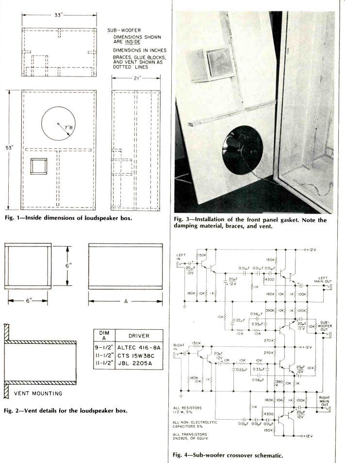
Fig. 1-Inside dimensions of loudspeaker box.
Fig. 2-Vent details for the loudspeaker box.
Fig. 3-Installation of the front panel gasket. Note the damping material, braces, and vent.
Fig. 4-Sub-woofer crossover schematic.
We now begin to see why almost all commercially available systems cut off between 40 and 60 Hz. There is little of musical interest below 40 Hz and system distortion increases rapidly as the system low frequency cut off goes down.
But suppose, Gentle Reader, that you, like the author, still want to feel those 20 Hz signals from a synthesizer while retaining reasonable efficiency and tolerable distortion in your system. This can be done with the addition of a subwoofer. A sub-woofer is a low bass loudspeaker, generally used in a bridged-center configuration, which handles material below the range of the normal system's woofer. It offers two advantages. One, quite obviously, is extended bass response and the other is reduced distortion in the main system. This reduction in distortion is caused by easing the low frequency requirements on the main woofer. Let us apply current loudspeaker synthesis procedures to the design of a sub-woofer and see what sort of system results.
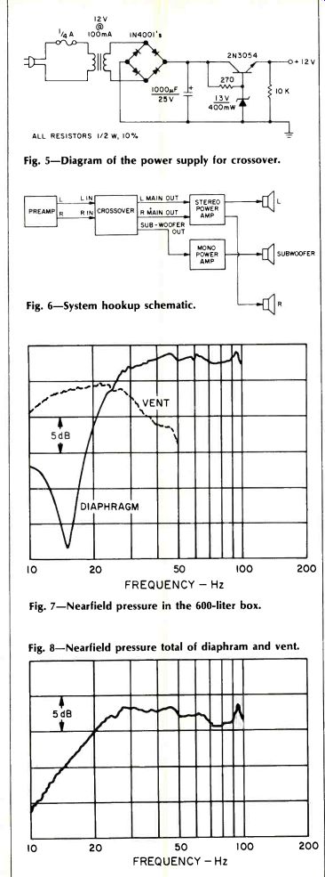
Fig. 5-Diagram of the power supply for crossover.
Fig. 6-System hookup schematic.
Fig. 7-Nearfield pressure in the 600-liter box.
Fig. 8-Nearfield pressure total of diaphragm and vent.
Designing a Sub-Woofer
Before going any farther, we need to firmly establish our design objective. Let us try for a low frequency cut off of 20 Hz in a system with maximally-flat response. With this goal in mind, we must now choose the type of system and the alignment we will use. Since the low cut off requires a large box for reasonable efficiency, we should choose a type of system and alignment which will maximize efficiency per unit volume, and this means a vented-box. For an alignment, let us choose the 4th-order Butterworth (B4) which is maximally-flat. The Quasi-Butterworth 3rd-order (QB3) alignments are also flat, but require the driver resonance frequency to be lower than the system cut-off frequency. In the case of a 20 Hz cut off, this is an unreasonable requirement. Also, the QB3 alignments are more prone to problems caused by infrasonic signals, such as turntable rumble, than is the B4.
Next, we must fix the enclosure volume. 600 liters (21 ft') is about the largest box that the author can squeeze into the living room of his small apartment; therefore, let VB be 600 liters. This volume, when plugged into Eq. 1 along with the k,t of a B4 alignment and 20 Hz cut off, gives an efficiency of just over 1.0%.
Similarly, we must set the upper frequency limit for the sub-woofer. The 60-liter bookshelf systems (A & I Sound A060s) in the author's apartment have a moderate 4th-order Chebbychev (C4) alignment with a 45-Hz cut off. Good engineering practice requires about an octave of overlap between the crossover frequency and the acoustical cut off of a driver ...
2x45 Hz=90 Hz (3)
... which can be rounded off to 100 Hz. This figure will give suitable overlap for systems with f:,'sin the 40- to 60-Hz region. The sub-woofer's response should extend an octave above the crossover. The formula below gives an approximate relationship between advertised basket diameter in inches (AD) and the upper acoustical cut off (fpR) of a driver.
ADmax = 11,000
fPR (4)
Plugging fpR of 200 Hz into Eq. 4, we find that a driver with an advertised diameter of up to 55 in. would be useful. Since no one makes a 55-in. loudspeaker, we should try something smaller. We could use an 18-, 24-, or 30-in. unit. Since there are so few drivers from which to choose, let us limit ourselves to 15-in. units.
A. N. Thiele has given us a very useful table of potential vented-box system alignments. The table was reprinted in the August, 1975, issue of Audio. 'Referring to the table we find that for a 20-Hz B4 alignment in a 600-liter box, we want to use a driver with a resonance frequency (f5) of 20 Hz, a total Q (QTS) of 0.38, and a compliance equivalent volume (VAS) of 850 liters. The table gives the parameters of three potentially useful drivers, the Altec 416-BA, the CTS 51W38C, and the JBL 2205A. In the case of the Altec driver the QTS is too low, but it may be raised by adding a series resistor (R5) which should have a power rating comparable to that of the driver. The VAS of the JBL driver is too low to allow for a B4 alignment, but does allow a C4 alignment with less than 0.1 dB of amplitude ripple. Again, the QTS needs to be adjusted with a series resistor.
How to Build a Box
Each of the three possible systems uses the same basic enclosure with changes in the length of the vent and the addition of a series resistor being the only variations on the theme. The inside dimensions of the enclosure are 21 x 33 x 53 in. The walls should be made of 3/4-in. (or thicker) plywood. All the joints should be braced with glue blocks and secured with screws and glue. Note the use of the 1 x 4 in. braces. These steps are to insure that the enclosure is free of spurious rattles and resonances. The vent may be constructed of ½- or ¾-in. plywood or particle board.
The enclosure should be lightly lined on three of the inside surfaces (e.g. top, back, and one side) with an absorptive material. The purpose of this material is to control standing waves inside of the box; it is not for the purpose of acoustic damping of the driver. Therefore, the material should be used sparingly and kept away from the driver and the vent. The principle "some is good, so more is better" does not apply in this case.
The first box standing wave will be in the stop band of the crossover filter. A small amount of damping material, together with the action of the crossover, will keep the standing waves from being excited by transient material such as music. In the prototype system, one layer of 1/2-in. thick polyurethane foam, similar to the type used for microphone windscreens, was found to be sufficient.
The front panel should be secured to the enclosure with plenty of screws. A gasketing material, such as Moretite, should be used to seal the joint between the front panel and the rest of the enclosure and to seal the joint between the driver and the front panel.
The Crossover
Unless a huge amount of floor space is available, it is best to use the sub-woofer as a bridged-center speaker. While it is possible to realize a passive network to go between the two power amplifiers, the two main speakers, and the sub woofer, the inductors and capacitors would have to be very large and very expensive. The author was fortunate to have a spare mono power amplifier and, so, implemented an active crossover. The crossover consists of 3rd-Order Butterworth (18 dB/octave) networks. The reasons for selecting this filter type are beyond the scope of this text. (Author's Note: wanted to use that line in a paper or article since I was a sophomore in college; I hope the Kindly Editor leaves it in the article. For a good discussion of crossovers, see Ashley & Kaminsky.) 8 (Kindly Editor's Note: Sure, W.J.J., my pleasure, particularly since my personal favorite line, Baranek's Law, is used later in your paper.) One problem with many active crossovers is transient intermodulation distortion (TIM). The author's preamp and power amps are old TIM-free valve units. Previous attempts to build the filters using monolithic IC amps resulted in very bad "transistor sound." These filters were redesigned using transistor emitter-follower circuits which were TIM-free.6 ' Standard 5% tolerances for the resistors and capacitors are tight enough for a crossover such as this one.
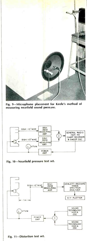
Fig. 9-Microphone placement for Keele's method of measuring near-field sound pressure.
Fig. 10-Nearfield pressure test set.
Fig. 11-Distortion test set.
The Results
--------
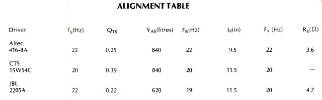
ALIGNMENT TABLE
Fs is resonance frequency of the driver, QTS is the total Q of the driver, VAs, is the compliance equivalent volume, FB is the resonance frequency of the enclosure, IP is the length of the port, F3 is the low frequency cut off, and Rs is the value of the series resistor needed to trim the system.
The prototype enclosure was assembled, and the CTS 15W38C was installed. The frequency response was measured using Keele's nearfield sound pressure method.9The response is shown in Figs. 8 and 9. The response of the complete system (Fig. 9) is down 3 dB at 20 Hz which is as theory predicted. The equipment set up used in this measurement is shown in Figs. 10 and 11.
The system distortion was measured using Klipsch's method 3with the test set diagrammed in Fig. 11. Figure 12 is the plot from the spectrum analyzer. The loudspeaker was radiating two frequencies-f i of 27.5 Hz (A0)and f 2 of 82.6 Hz (E2)--each at a SPL of 95 dB re20 u Pa measured at 1 m. The total harmonic distortion was 2.6%, a tolerably low value.
More important, the modulation distortion was only 1.1%, a very good value for a direct radiator system at such a high output power.
The system impedance was also measured. The magnitude of the minimum value of the impedance was 7.2 Ohm. An 8 Ohm rating would be justified for this system.
Conclusions
The measured response of the system is in reasonable agreement with what theory predicted. So, from that point of view, the project was successful.
Was it worth the trouble? The answer must be a qualified yes. On most program material it is not possible to hear any benefit from the sub-woofer. In this case it is not used, and the smaller main system handles everything.
In the case of electronic music the sub-woofer is, for the author, worthwhile. Switched-On Bach and other albums have a wealth of program material in the range of the sub woofer. Of course, the author may be suffering from the effects of Beranek's Law: "It has been remarked that if one selects his own components, builds his own enclosure, and is convinced that he has made a wise choice of design, then his own loudspeaker sounds better to him than does anyone else's loudspeaker. In this case, the frequency response of the loudspeaker seems to play only a minor part in forming a person's opinion."
-L. L. Beranek, Acoustics, McGraw-Hill, 1954, p. 208.
Acknowledgements
The author would like to thank Mr. Ken Bohleber of CTS of Paducah for his kind assistance in assembling the prototype system and tolerating a 600-liter box taking up space in the office/lab which he shares with the author.
Is 20 Hz low enough? How about 12 Hz? The author has designed a system using the same basic enclosure, with a different vent, and a CTS 18W54C. The system has an f3 of 12 Hz. Thrill to the feel of 64-ft. organ pipes, thunder, earthquakes, and other natural disasters! For details, contact the author.
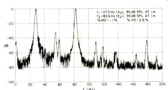
Fig. 12-Plot from the spectrum analyzer.
References
(1) Ashley, J. R. and W. J. J. Hoge, "A Systems Approach to the Loudspeaker in a Monitoring Environment," presented at the 51st convention of the Audio Engineering Society, Los Angeles May, 1975.
(2) Small, R. H., Direct-Radiator Electrodynamic Loudspeaker Systems, Ph.D. Thesis, University of Sydney, 1972.
(3) Klipsch, P. W., "Modulation Distortion in Loudspeakers," Jour. Aud. Engr. Soc.; Part 1, April, 1969; Part 2, February, 1970; Part 3, December, 1972.
(4) Thiele, A. N., "Loudspeakers in Vented Boxes," Proc. IRE (Aust.), August, 1961.
(5) Newman, R. J., "A. N. Thiele: Sage of Vented Speakers," Audio, August, 1975.
(6) Thiele, A. N., "Loudspeakers, Enclosures and Equalizers," Proc. IREE, November, 1973.
(7) Shepard, R. R., "Active Filters: Part 12-Short Cuts to Network Design," Electronics, August 18, 1969.
(8) Ashley, J. R., and A. L. Kaminsky, "Active and Passive Filters as Loudspeaker Crossover Networks," lour. Aud. Engr. Soc., June, 1971.
(9) Keele, D. B., Jr., "Low-Frequency Loudspeaker Assessment by Nearfield Sound-Pressure Measurement," Jour. Audio Engr. Soc., April, 1974.
(Source: Audio magazine; Aug. 1976)
Also see: Doppler Distortion in Loudspeakers (Aug. 1976)
= = = =