James Moir [James Moir & Assoc., Chipperfield, Herts. WD4 9JJ, England.]
Of the many distortions produced by loudspeakers, the most controversial is probably Doppler distortion, some experts claiming that it does not exist, while others, notably Paul Klipsch and this writer, believe it to be the predominant residual distortion in cone-type systems.
Researchers may theorize for years over the subject of its existence and significance, but actual measurements of the distortion should short circuit much of the discussion, particularly when the argument against its importance is based on unsupported assumptions. This contribution includes such measurements on a variety of 42 loudspeaker systems, many of the measured values having the great additional merit of being taken on the speakers while they are reproducing normal program material, speech and music. In minimizing the use of the standard sinusoidal test signal, it is believed that they set a new approach to the measurement of distortion. A little of the basic theory is perhaps a good start to the subject.
Frequency Intermodulation Distortion
Consider a loudspeaker reproducing two tones having frequencies f, and f 2 with a frequency ratio of 20 to one, then while the loudspeaker cone is moving towards the listener to reproduce one half cycle of the lower frequency, f it will simultaneously reproduce 10 complete cycles of the higher frequency, f2. While the cone is moving away from the listener on the reverse half cycle of the lower frequency, it will reproduce the second 10 cycles of the higher frequency. This is the classical Doppler situation, the pitch of the higher frequency as heard by the listener being increased as the source moves towards the listener, and decreased as the source moves away from the listener.
An observer listening to a signal frequency, f2, from a source moving towards him with a velocity, v, hears the resultant note with a frequency, f'2, where, f'2=f2(c+v)/c and c = velocity of sound in air. When the source is moving away from him he hears the note as having a frequency, f"2=f2(c-v)/c The velocity of sound in air is around 1125 ft./s and the velocity of the speaker cone generally below 10 ft./s but dependent, of course, on the frequency and amplitude of the lower frequency. Thus, the maximum change in pitch (frequency) due to the Doppler effect is in the region below 1%. In FM transmission parlance, the Modulation Index (defined as Carrier Frequency Deviation ± Modulation Frequency) is very low.
When the moving source is a loudspeaker diaphragm executing a sinusoidal motion at the lower frequency while reproducing a high frequency tone, the pitch of the high frequency tone as heard by the listener will vary cyclically between the two limit frequencies quoted above at the frequency (f,) of modulation, a simple example of frequency modulation.
The mathematics of this are well understood, the known result being the appearance of two sidebands, symmetrically disposed about the carrier frequency, f2, at frequencies (f2+f,) and having amplitudes that are an indication of the extent of the Doppler distortion. It is necessary to differentiate between the value of the carrier frequency shift, Oft measured in Hertz, and the frequency at which the sidebands due to this shift appear. The carrier shift is an indication of the extent of the Doppler distortion, and it is at its acceptable limit when it is only 20 to 30 Hz. The sidebands are always spaced from the carrier at the frequency of the low frequency modulation, f irrespective of the amount of Doppler distortion, because the carrier frequency deviation is cyclic at this modulating frequency. Measurements of the Doppler distortion are made rather difficult because there is a second form of distortion that produces sidebands at exactly the same frequency as the Doppler mechanism.
Amplitude Intermodulation Distortion
These similar distortions appear when the same two-frequency test signal is applied to any device that has a non-linear input/output characteristic. If two sinusoidal voltages, V i = V sin (23rf,t) and V2 = sin (22rf2t), are simultaneously applied to a device having a transfer characteristic represented by the power series,
Vi, =a,V+a2V2+a3V3+a,V4 (3)
the output will include in addition to the harmonics of the two test tones, f, and f2, two sidebands having frequencies of (f2+f,) and (f2-f1) with amplitudes in proportion to the coefficients a2 and a, etc., in Equation 3. It will be seen that the frequencies of these two sidebands are identical to those produced by Doppler frequency intermodulation but the amplitude of the two sidebands is determined by an entirely different factor, the degree of amplitude non-linearity in the device. The extent of this non linearity is indicated by the value of the coefficients a2 and a, in the power series of Equation 3. The sideband frequencies produced by this amplitude dependent intermodulation are subsequently referred to as the A.I.M. sidebands. These A.I.M. sidebands are produced in loudspeakers by nonlinearities in the suspension, non-uniform distribution of the magnetic field in the gap, and at higher frequencies by non-linearities in the cone material and in the magnetic system.
The distortion spectrum that results from applying two separate test frequencies is in the simplest example like that shown in Fig. 1. The two side bands, f2+f have amplitudes that are the sum of the Doppler and amplitude modulation components, whereas the f2 ±2f, are almost invariably due to amplitude intermodulation alone. The remaining two distortion components are the first two harmonics of the two test frequencies f1 and f2.
It should be remembered that the presence of the amplitude dependent sidebands implies the simultaneous presence of the ordinary harmonic distortion components having frequencies of 2f,, 3f,, 2f 2, 3f2, etc. These have no equivalent in the frequency intermodulation case, so for equal amounts of distortion power in the Doppler and A.I.M. sidebands, the total distortion power due to the amplitude dependent distortions, the harmonics and amplitude intermodulation components, will usually be much greater than the total distortion power in the Doppler sidebands.
The first order intermodulation sidebands having frequencies of f2}1 due either to Doppler or amplitude intermodulation, are seen to form only a small part of the total distortion power, but their effect in degrading the quality of the sound is not indicated by merely comparing the total power in the amplitude distortion components to the power in the Doppler distortion components. Critics have sometimes based their estimation of the importance of Doppler distortion on a comparison of the respective powers in the distortion products and on this basis come to the conclusion that Doppler distortion is not significant, but this cannot be justified.
It has generally been considered that the amplitude dependent distortions were the prime cause of much of the residual distortion in loudspeakers. Perhaps it should be remembered that it has never been conclusively demonstrated that the addition of the lower order harmonics alone results in any significant loss in sound quality. Thus, violins of unquestionable tonal quality differ markedly in their harmonic structure.
The quality deterioration that is evident when harmonic distortion is present in an amplifier or loudspeaker is more reasonably assumed to be due to the sidebands components (f2±f,), (f2±2 f,), etc., that inevitably accompany harmonic distortion in a loudspeaker, but do not accompany the harmonics in musical instruments.
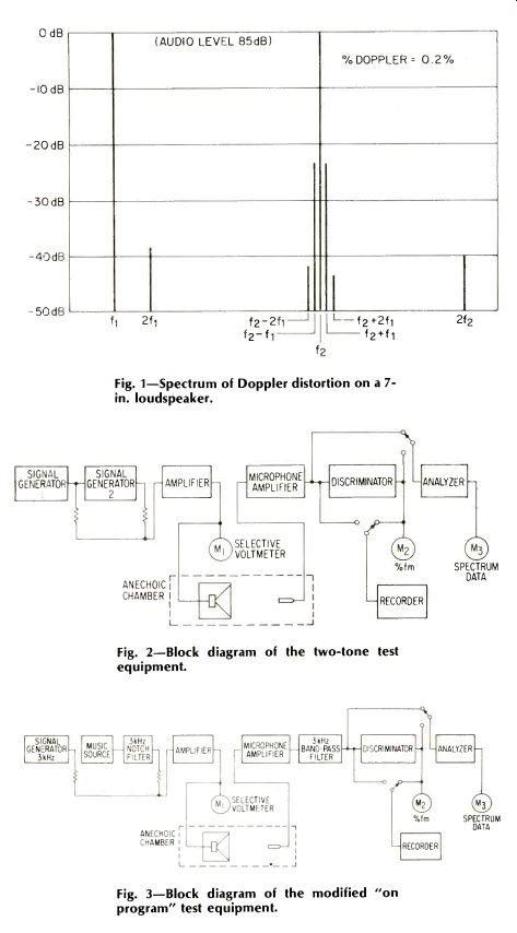
Fig. 1-Spectrum of Doppler distortion on a 7 in. loudspeaker.
Fig. 2-Block diagram of the two-tone test equipment.
Fig. 3-Block diagram of the modified "on program" test equipment.
Measurement Technique
Separate determination of the amplitudes of the amplitude intermodulation and Doppler sidebands has evidently proved difficult if judged by the complexity of some of the techniques that have been used.
The technique to be described provides a simple method that not only separates the two sets of sidebands from each other even though they have the same frequencies, but allows the Doppler sidebands produced by the loudspeaker to be separated from the music being reproduced by the same loudspeaker.
Our technique is to insert an amplitude limiter and FM discriminator designed for a carrier frequency of 3 kHz into the measuring system. This particular carrier frequency was chosen as it allows the data obtained to be compared with that obtained by other investigators when assessing the subjective effect of wow and flutter, a very similar form of frequency inter modulation distortion.
The arrangement of the test equipment is shown in the block diagram of Fig. 2. Test signals are provided by two Bruel & Kjaer type 1014 signal generators, adequately decoupled and fed via a Quad type 303 50-watt amplifier to the loudspeaker under test mounted in the open air. The output signal from the loudspeaker is picked up by a Bruel & Kjaer type 4131 microphone mounted on the axis of the speaker at a distance of 1 meter, amplified and then fed in parallel to the 3-kHz limiter and discriminator and to a Marconi type 2330 narrow-band analyzer. Meter M i checks the amplitude of the two separate input signal components f1 and f2 and the total amplitude of the combined signals, meter M2 reads the FM distortion components only, while Meter Mi indicates the amplitude of each of the individual components of the speaker output signal spectrum. The reading of M, is proportional to the frequency deviation of the carrier f1. This is related to the modulation index, M, by the simple relation,
M = (Jf., x fl)/f,
With the narrow band analyzer switched to the output of the microphone amplifier, it will read the rms sum of the amplitude intermodulation and frequency intermodulation components at that particular frequency. When switched to the output of the discriminator, it will read the amplitude of the FM component only. The amplitude of the AM component can be determined by subtracting the FM component from the total. In the first test to be described two sinusoidal tones were used for the investigation, a low frequency signal around 70 to 90 Hz with a high frequency signal of 3 kHz being employed.
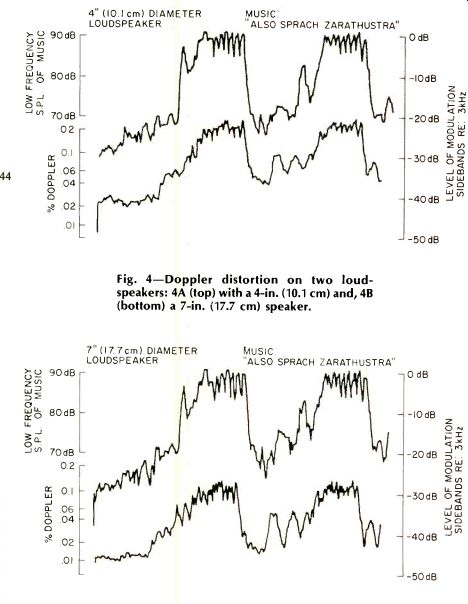
Fig. 4--Doppler distortion on two loudspeakers: 4A (top) with a 4-in. (10.1 cm) and, 4B (bottom) a 7-in. (17.7 cm) speaker.
Test Samples
Three speakers of different sizes were used for the preliminary investigation but the data is typical of many other speakers tested. The choice was biased towards demonstrating the effect of radiator size on the AM and Doppler distortions.
The first unit tested was a 12 in. (30.4 cm) cone speaker covering the full audio range mounted in a ported enclosure having a volume of 3,200 cu. in. The second was an enclosure of 1498 cu. in. using a single 7 in. (17.7 cm) diameter unit to cover the full range. The third was a 4 in. (10.1 cm) diameter unit in an enclosure of 400 cu. in. All three systems were operated at an on-axis sound pressure level of 85 dB at the modulating frequency f , of 90 Hz. It is appreciated that this may be a little below the sound level at which the hi-fi enthusiast may operate his system but it enables the performance of the three systems to be compared at the same sound level without grossly overloading the smaller units.
In all cases the level of the lower frequency, f was varied over a range sufficient to confirm the expected relation between sound pressure level and distortion.
Test Data
The 4-in. diameter unit happened to be the first to be measured, and the result was rather surprising for the calculated values of Doppler distortion agreed almost exactly with the values measured by the analyzer, the side band amplitudes being the same when the analyzer was connected either to the output of the microphone amplifier or to the output of the discriminator. This implies that all the (f2±f1) sidebands were due to Doppler distortion and that the amplitude intermodulation contributed little to the total amplitude of the sidebands.
Our initial surprise led to some very careful rechecking of the whole measuring system and of other speakers, and we gradually came round to the obvious conclusion that practically all the intermodulation distortion in small units was due to Doppler.
Data on three systems is contained in Table 1 from which it will be seen that when using a speaker with a cone diameter of seven inches, the Doppler intermodulation distortions exceeded the amplitude intermodulation distortions at the same frequencies by 16 dB, confirming the theoretical prediction that when operated at the same acoustic power level small speakers produce more distortion than do large speakers. The oft repeated claim that a small cone performing a large excursion is just as good as a large cone executing a small excursion is seen to be an over-simplification of the situation. The acoustic signal "knows" whether it has been radiated by a small loudspeaker or a large loudspeaker. It should be emphasized that the use of "long throw" units with very flexible linear surrounds is no solution to the Doppler distortion problem, though their use does minimize the amplitude dependent intermodulation distortions.
It will also be seen that in typical units having cone diameters less than about 12 inches, the Doppler distortion sidebands greatly exceed the amplitude intermodulation side bands. As the previous discussion shows that these Doppler distortion components have the same frequency as the distortion components due to amplitude intermodulation, it is apparent that in the typical units tested Doppler distortion is a more serious cause of sound quality degradation than is amplitude intermodulation, quite contradicting the generally held view.
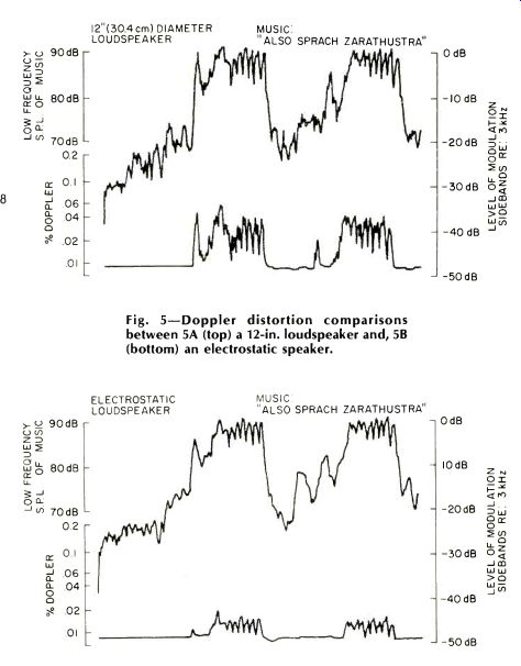
Fig. 5-Doppler distortion comparisons between 5A (top) a 12-in. loudspeaker and, 5B (bottom) an electrostatic speaker.
Cone diameter (in.) | Amplitude (dB) | Frequency (dB)
4 -40 -16
7 -41 -25
12 -43 -41
Table 1--Intermodulation Distortion in Typical Speaker Systems.
However, the interesting aspect is the possibility of measuring the Doppler distortion while the loudspeaker is reproducing program material.
Two-tone testing, using sine wave signals, produces accurate data that applies in the test conditions, but it requires a semi-arbitrary choice of the test tone frequencies and their relative amplitudes. Even with this information, it is necessary to decide whether these conditions are relevant when reproducing music. It occurred to this writer that it should be possible to measure the extent of the Doppler distortion while the loudspeaker was actually reproducing music, the technique being as follows: The block circuit diagram is shown in Fig. 3, a modified form of the current shown in Fig. 2. A flutter-free, 3-kHz test signal is inserted in the music program by inserting a notch filter tuned to 3 kHz into a suitable point in the output of the tape recorder to attenuate the 3-kHz components of the music, and replacing these with a 3-kHz, flutter-free tone from a suitable signal generator. The amplitude of this test tone is held constant at some suitable value.
When the music is being reproduced, the cone excursions due to the low frequency components of the music Doppler modulate the 3-kHz test signal in just the same manner as they modulate any high frequency component of the music. The loudspeaker output signal derived from the microphone is then passed through a band-pass filter that eliminates all the frequencies except those in a narrow band centered on 3 kHz and including the Doppler modulated 3-kHz test signal. This narrow band is then passed through the 3-kHz demodulator and the amplitude measured by a suitable meter and chart recorder.
To obtain simultaneous recordings of the program signal and the consequent distortion, the chart recorder was switched to the output of the microphone and a standard piece of music replayed from a professional 15 ips tape recorder. This produced the top trace on the charts, as shown. The chart and tape were then rewound and the music repeated with the chart recorder connected to the FM discriminator output. This produced the lower trace showing the variation in the Doppler distortion as the signal amplitude varied.
Figures 4, 5, and 6 illustrate some of the information obtained on several speaker systems including several very expensive enclosures. The curves of Figs. 4A and 5A illustrate the results obtained using 4-in. and 12-in. diameter units in suitable enclosures, and it will be seen that Doppler distortion in the smaller unit is about five times higher than in the 12-in. unit.
No self-respecting designer would rely today on a single unit to cover the whole audio band, and two, three, and four unit assemblies are the common solution to the problem of obtaining a wide overall frequency response. It is often claimed that this division of responsibilities is also a solution to the Doppler distortion problem, but the curves of Fig. 6 show that this is not necessarily true.
Figure 6B is an indication of the performance of an expensive three unit system with a sub-optimum choice of changeover frequencies and crossover network design. It will be seen that the performance is little better than that of a single 12-in. unit, at least in respect of Doppler distortion, the Doppler distortions being some 30 dB below the level of the 3-kHz test tone.
That a multiple unit system can be a solution is indicated by the curves of Fig. 5B taken on a well-known, wide range electrostatic speaker system.
The Doppler distortions are seen to be about 45 dB below the test tone level, some 15 dB better than the expensive 3 unit system of Fig. 6B.
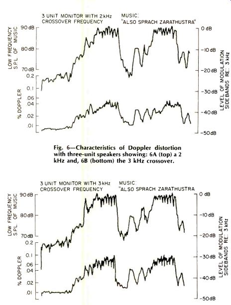
Fig. 6-Characteristics of Doppler distortion with three-unit speakers showing:
6A (top) a 2 kHz and, 6B (bottom) the 3 kHz crossover.
Significance of Doppler Distortion
That Doppler distortion does occur can hardly be disputed in view of these and similar results published by Klipsch, but it is more difficult to decide on the significance of the distortion when it occurs in a loudspeaker. It is clearly unreasonable to claim that it is less important than amplitude intermodulation distortion where the measurements show that the inter modulation sidebands produced by Doppler are of greater amplitude than the amplitude intermodulation side bands at the same frequency that results from non-linearity in the loudspeaker.
We attempted a separate assessment with a small listening crew. The Doppler sidebands in the 3-kHz region were removed from a recording by suitable filters and tape recorded.
Amplitude dependent sidebands in the same frequency band were similarly obtained by filtering the output of a slightly overloaded amplifier playing the same piece of music. The two sets of recorded side bands were then compared while being replayed at the same loudness level. Both observers were agreed that the Doppler sidebands were more annoying than an equal percentage of the amplitude intermodulation sidebands. That they should be more annoying than an equal percentage of amplitude inter modulation distortion is rather surprising and no explanation is offered, but the result is recorded for later consideration.
Some lower key confirmation was provided by a review of some earlier tests. Several months before the commencement of the investigation, three good loudspeaker systems had been subjectively compared and ranked by two observers. Some months later when the Doppler measuring equipment had been assembled, the three systems were objectively assessed. It was then found that the earlier subjective ranking in respect to "roughness" agreed exactly with the later objective ranking in respect of Doppler distortion. By that time both observers had considerable experience in recognizing Doppler distortion in a loudspeaker and they were agreed that the "roughness" commented on many months earlier was indeed due to Doppler.
Though we have not had an opportunity of objectively assessing the Doppler distortion content of a good horn-type loudspeaker, we believe from simple listening tests that their characteristic clarity is largely due to the absence of Doppler distortion.
The same comment can be made about the performance of the wide range electrostatic loudspeaker.
Bibliography
The subject of Doppler distortion in loudspeakers was first raised by: Beers & Belar, "Frequency Modulation Distortion in Loudspeakers," Proc IRE, Vol. 31, No. 4, April, 1943, followed by a series of papers and letters by Paul Klipsch in the Journal of the Audio Engineering Society between April, 1958, and February, 1970. The writer's interest in the subject was aroused in 1947 when investigating the performance of horn loudspeakers for use in cinemas. In January, 1967, Hi-Fi News published a series of test results on typical loudspeakers, and in 1973 the author presented a paper at the AES Convention in New York describing the technique for measuring Doppler distortion in loudspeakers while the speaker was reproducing music and speech. This was updated in a contribution to Wireless World for April, 1974, and is again updated by the present paper.
(Source: Audio magazine; Aug. 1976)
Also see:
Summer Sound Systems (Aug. 1976)
= = = =