Building The Vifa/Dayton Aluminum MTM Kit
By Edward T. Dell , Jr.
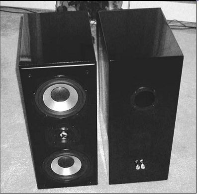
PHOTO 1: THE ASSEMBLED MTM UNITS ARE QUITE HANDSOME, EVEN WITHOUT THEIR
SUPPLIED GRILLES. THE KIT ASSEMBLES EAS ILY IN NO MORE THAN FIVE TO SIX
HOURS.
Parts Express
725 Pleasant Valley Dr.
Springboro, OH 45066-1158
1-800-338-053, Fax: 1-937-743-1677, www.partsexpress.com
Part no.: 302-940, black
Dimensions: (W × D × H) 9 × 13.5 × 22”
List price: $799.
MSRP $493.62/pair.
Available: cherry, beech, gloss black finishes Impedance: 4 ohm Frequency response: 40Hz-35kHz SPL: 86.5dB Power handling: 150W Over the last decade Parts Express has become a major player in the loudspeaker market both at the consumer and OEM level. Their retail interest reflects a strong commitment to kit projects for the amateur builder, and this mid-tweeter mid (MTM) D'Appolito-style bass-reflex kit (Photo 1) is a good example.
The kit comes completely finished with a mounted front panel and central interior sub-panel, making the space inside the relatively small 1ft^3 cabinet a bit awkward to work in. The cabinets are constructed of ¾” high-density particle board, beautifully finished with either cherry or beech veneers or a high-gloss piano black lacquer.
CONTENTS
Parts Express does a fine job of packing the kit, which arrives in three boxes (Photo 2), two for the cabinets and one for the remainder of the parts. The kit is complete (Photo 3), with sheets of foam for lining half the inner cabinet surfaces, four 7” Dayton mid-bass aluminum cone drivers, two Vifa D25AG35-06 aluminum diaphragm tweeters, two 2½” diameter adjustable port tubes, an 11-page manual, etched circuit cards for crossover assembly, bags of crossover components, driver sealing caulk, "stakon" terminated wire harnesses, speaker edge caulk, screws, and a tube of mounting adhesive. The builder needs only to add solder and possibly hot melt glue if s/he prefers that method of mounting the 2kHz crossovers.
The manual lists required simple tools and provides an assembly order that makes good sense. An inventory of included parts allows you to check for missing parts and a number to call for remedies. You'll need a well-padded workplace to preserve the very high quality finish. The manual combines some photos from other kits which are offered in unfinished form and without the mounted central baffle and front panel. This is slightly confusing, but not fatal. It does make some of the instructions irrelevant, however.
The very handsome cabinets are drilled for four plastic grille-mount posts, which are the first installation task. The cutouts for mounting the two 7” aluminum mid-woofers are rabbeted to seat the rims flush with the front panel, as is true of the Vifa tweeter mounting (Photo 4). This minimizes the possibility of diffraction problems. The straight (non flared) telescoping port tubes must be adjusted and glued to the correct length, mounted with #6 ¾ screws, to effect a tuned box format.
The pairs of supplied binding posts are very high-quality, and you can mount them directly through the rear cabinet wall on ¾” centers (Photo 5) witha hammer, after removing the main nut used to secure the input speaker wire.
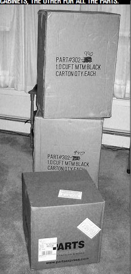
PHOTO 2: THE KIT ARRIVES IN THREE COMPETENTLY PACKED CARTONS, TWO FOR THE
CABINETS, THE OTHER FOR ALL THE PARTS.
Use the nuts, lock washers, and a solder tab to secure this hardware inside the cabinet wall. A hollow nut driver can help here, but gas pliers or an adjustable wrench also work, but with greater difficulty. Bend the solder tabs outward to make soldering to them easier. You will need 2” thick padded blocks to support the cabinet for work on the front panel to avoid stress on the binding posts.
The kit contains pieces of expanded foam with an undulating surface to damp internal reflections. The manual suggests covering half the eight surfaces formed by the central extra baffle mounted mid-cabinet. Use a sharp knife or sturdy scissors to cut the four pieces to fit. I installed the foam as instructed, since in building a kit for review I al ways follow instructions exactly.
KIT ASSEMBLY
If I were assembling this kit independently, I would advise a variation of the instructions. According to the manual, you should mount the crossover in the bottom-rear section, just below the input terminals. This makes the board very hard to reach. I checked the wire sup plied and such an alternate location in the front floor section will work fine, and would be much easier to reach in final assembly. This would mean that the foam piece on the top of the cabinet would be installed in the front section and that for the bottom would sit in the rear. I doubt the change would make any acoustical difference in performance.
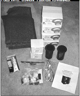
PHOTO 3: THE KIT CONTENTS WHERE EVERY THING EXCEPT SOLDER IS SUPPLIED.
THE WIRING HARNESSES COME CUT TO LENGTH AND SUP PLIED WITH "STAKON" PUSH-ON
TERMINALS.
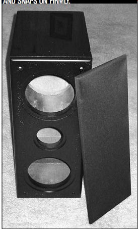
PHOTO 4: THE CABINETS FOR THE KIT ARRIVED FULLY ASSEMBLED OTHER THAN INSTALLING
THE SNAP-ON GRILLE MOUNTING POSTS. THE GRILLE COMES PRE-ASSEMBLED, AND SNAPS
ON FIRMLY.
(This might cause some interaction be tween the crossover coils and the driver coil, but I did not test this arrangement.) You are asked to re-shape the supplied caulking into strands about ¹/8” in diameter to be placed around the outer rims of the drivers. The photo is a bit confusing since it shows the caulk placed, not on the outer rim, but nearer the supports for the magnet/coil assembly. I placed the caulk near the edge to make an air tight seal for the drivers. You want all the internal air pressure to go through the port, of course.
Assembling the crossovers is simple and well-supported by the instruction photos. The circuit boards are easy to use and well laid out. Some of the capacitors are longer than the hole-spacing, requiring careful shaping of the leads in order to fit snugly against the board.
I followed my usual practice of skinning any oxidation from component leads by carefully scraping them with a wire cut ter. You must also remove the insulation coating on the coil lead wires by scraping with a sharp knife.
You first glue the three coils, four capacitors, and two resistors to their proper locations. The coils are further secured using wire ties, a great invention (Photo 6). The manual has several photos clearly showing where components are located.
Good, slow, careful soldering is mandatory, as always. Double-check your work to avoid later changes to boards al ready glued in place. Note carefully the connector terminals on the board. The inputs are clearly marked for polarity, as are those for the tweeter.
The four mid-woofer terminals could be confusing. Those nearest the corner are the two negative connectors, the two toward the center are the positive terminals. It is possible to wire incorrectly here as I discovered the hard way. In a test I naturally had sound from the tweeter only.
Because my kit came with the front panel already installed, I found it easier to mount the drivers last. In preparation for that, I carefully separated the handy wiring harnesses for the three drivers and the one for attaching the crossover to the input terminals. I identified each for its destination since the wires' lengths vary. It is imperative that you fully illuminate the cabinet interior for the final assembly (Photo 7). A flash light helps as well.
I soldered the input wiring to the terminals first. Next I connected the harnesses to their respective lugs on the crossover board. Then I glued the cross over in place (Photo 8). This procedure is much easier for this kit than the instructions' advice to mount the internal baffle and drivers in the front panel be forehand. If the front panel was not in stalled, the manual's instructions would work well.
However, all went smoothly after I re connected the woofer wiring correctly, and the full sound of the pair was very gratifying.
The 302-940 kit and its other versions at under $250 each are a remarkable bargain, and well worth any audiophile's serious consideration. Parts Express has put together a high-quality product offering which makes an eloquent case for those audiophiles who like to have a hand in acquiring their sound systems.
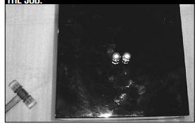
PHOTO 5: HIGH-QUALITY INPUT TERMINALS ARE MOUNTED ON THE LOWER BACK OF
THE CABINETS BY FIRST REMOVING THE NUTS FOR SECURING THE SPEAKER CABLES
AND USING A HAMMER TO PUSH THEM SNUG TO THE BACK PANEL. I USED A PLASTIC-FACED
HAMMER FOR THE JOB.
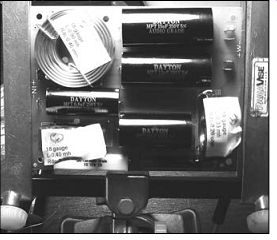
PHOTO 6: ASSEMBLING THE CROSSOVER IS SIMPLE AND WELL ILLUSTRATED IN THE
MANUAL. I LEFT LABELS ON THE COILS UNTIL FINAL SOLDERING TO MAKE SURE I
HAD LOCATED THE COMPONENTS CORRECTLY. THE COMPONENTS APPEARED TO BE VERY
HIGH QUALITY. AN ASSEMBLY VISE AIDS ASSEMBLY AND SOLDERING.
This pair could be an excellent part of a beginner's system, a dorm-room setup, improved sound for a computer, or as part of a home theater expansion. A great value that would be hard to beat at the much higher prices at a local mall.
I re-wrapped the cabinets in the soft protective plastic they arrived in, and re-packed them for shipment to Joe D'Appolito's lab for measurement, and final auditioning. His findings, along with Dennis Colin's listening critique, will be published next month.
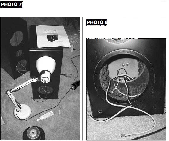
PHOTO 7: USE PLENTY OF LIGHT TO IN STALL THE FOAM DAMPING AND THE CROSS
OVER BOARDS.
PHOTO 8: THE MANUAL ADVISES PUTTING THE CROSSOVER NEAR THE REAR. I SUGGEST IT WOULD BE EASIER TO LOCATE IT NEAR THE FRONT. THE SUP PLIED WIRE LENGTHS ALLOW THIS.
-----------------
============
Also see: