We attempt to achieve “analog ecstasy on a shoe-string budget” with this low-cost phono preamp design.
If you are like me, you were probably won over to CD (digital) sound reproduction by the medium’s convenience, nonexistent noise, and promise of “perfect sound forever.” I gladly abandoned (sold) most of my vinyl records, with their surface noise, inner groove distortions, and time-consuming cleaning rituals. However, in the years since my switchover, I have had opportunities to listen to records with increasingly better turntables, cartridges, and electronics.
While I still like the convenience of my CD discs and iTunes downloads, I must admit that today’s good vinyl playback equipment can produce a degree of musical realism and satisfaction that my digital player (even with extensive mods) often can- not match. In an attempt to recapture some of the magic of listening to vinyl, I decided to pull out my audio parts box and build a dedicated phono preamplifier for the remaining records that I (thankfully!) still possess.
SELECTING A CIRCUIT DESIGN
I started out with the goal of building a design that would be simple, very inexpensive (under $150), and capable of relatively high quality performance. During my searches and queries, I ran across a very promising configuration that uses a single high-performance op amp with an active RIAA feedback net work. Highlights of this design include a feedback network that plateaus the RIAA curve above 50kHz. A great many records have been cut with this sort of equalization modification to save cutter heads from burnout dam age, and taking this into account will add a sense of openness and air to record playback.
This design also maintains a reasonable network loading of the op amp at higher frequencies, and the ability to couple the input signal without a capacitor.
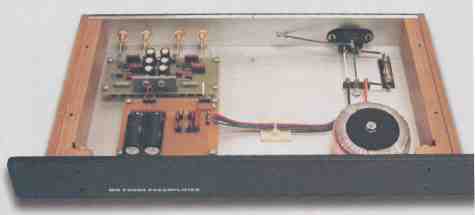
PHOTO 1: Front overall view of preamplifier.
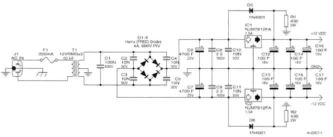
FIGURE 1: Preamplifier power supply. Harris (FRED) Diodes 4A, 600V PIV
THE POWER SUPPLY
The power system is a key factor in any audio component, and it can make a very significant sonic difference. The best sonics with this design will be produced using 12V DC lead acid batteries, provided that they have a very low internal resistance. I corresponded with one audio enthusiast who used batteries, and even installed a trickle charger in the preamp housing to maintain them. Due to cost and size considerations, I decided to use an AC-derived supply, which would also allow the unit to remain on for very extended break-in and warm-up periods.
My supply design, which is a balancing act between cost and performance, is shown in Fig. 1. The AC is input via a rear-mounted IEC connector, with the earth connection attached to the pre amp case for shielding. The earth ground is also routed to a rear panel lug for a turntable ground wire, and there is a circuit board jumper connecting the power supply ground to the earth ground. The fused power is routed to a 50VA toroidal transformer capable of sourcing over 4A of current
The secondary output is noise filtered and then rectified by a full wave bridge made up of 4A super-fast soft- recovery diodes, which have 0.01uF film capacitor noise snubbers in parallel. The rectified voltages are smoothed by low impedance 4700pF electrolytic capacitors, which have 2.2uF and 0.01uF film capacitor bypasses. This configuration produces approximately ±1W DC (under load from the circuit) to feed the voltage regulators on the preamplifier board.
A few notes are in order about the raw DC supply system. I used a toroidal type transformer to avoid the expense of an outboard housing, cable, w connectors. You should still keep UE tans- former 8” or more from the active circuit area to avoid induced circuit hum. Additional transformer shielding might reduce the required distance.
The super-fast soft-recovery diodes with snubbers greatly reduce diode-switching noise that might get through to the power rails. I also used point-to-point wiring and thick copper wire ground traces on the power board, which was fabricated using a standard pad-per-hole prototyping board.
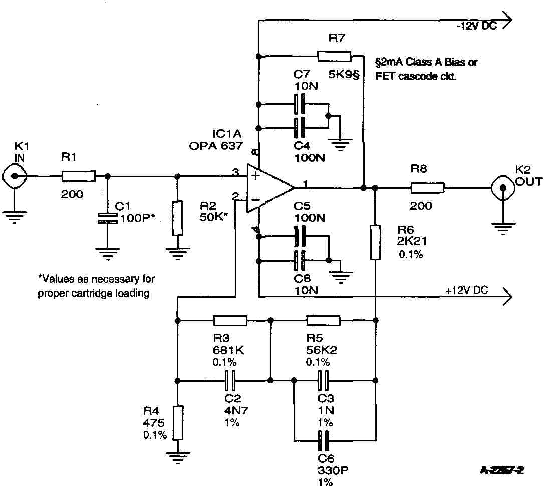
FIGURE 2: Phono preamplifier circuit.
The filtered DC from the power board feeds a pair of ±12V DC JRC (NJM) three-terminal regulators mounted on the main circuit board close to the op amps. The units chosen have very good ripple rejection specifications and low noise. This is a spot where, for still higher performance (at a cost), you would do well to check into some of the available higher-performance Linear Technology IC regulators. The outputs of the regulators each have three paralleled Black Gate F 100uF electrolytic capacitors. Note that there are also power resistors on the regulator outputs to produce a total current pre-load of approximately 42mA to bias the regulators into a region of better performance.
This supply design is much better than those of typical inexpensive commercial phono preamps. It provides a cost-effective level of sonic performance that is well suited to the goals of this project.
THE PREAMPLIFIER CIRCUIT BOARD
In an attempt to wring out maximum performance at cost, I employed several design tactics on the phono circuit board. I pre-mapped on graph paper the complete layout of all components, connections, voltage rails, and ground traces to ensure a compact, symmetric layout with minimum connections and solder joints. All of the wiring on the board is point-to- point, with no dielectric insulation involved, except at the solder pads on the board. In most cases, the leads of components serve as the traces between circuit points, and are positioned several thousandths of an inch away from the plane of the board. Note that the legs of the input and output resistors are directly soldered to the RCA jacks on the back panel to avoid the need for internal hook-up wires.
I also tried to adhere, where possible, to individual low resistance ground return paths on the phono board. There is a completely separate path from the RCA jack ground lugs to the power supply ground using bare Wonder Wire. The board, which is made of high-grade glass-epoxy material, is a prototyping style with plated copper pads per hole on 0.1” centers. Both of the circuit boards of the pre amplifier were very solidly mounted using 0.5” threaded hex aluminum spacers.
THE PREAMPLIFIER CIRCUIT
As I previously stated, I was attracted to the simplicity of a single, active feedback op-amp gain-stage design, even though I am aware of the arguments for a buffered passive RIAA equalization scheme. Both approaches have their advantages, but in the interest of cost and reduced circuit complexity, I went with the single-stage concept. This particular RIAA feed back network configuration, which was produced by audio enthusiast Thorsten Loesch has 44dB of gain at 1kHz, and is well suited to moving magnet cartridges with 3 to 5mV out put levels. There is also enough gain for some of the high-output MC cartridges. The circuit is illustrated in Fig. 2.
The op amp used is the Burr-Brown OPA 637, which is a premium-grade FET input design with a very high slew rate, fast settling, low noise, and mini- mum input offset voltage. This unit also allows for the omission of a signal input coupling capacitor, which further simplifies the circuit path. If you wish to keep costs down to a minimum, you could use the Burr-Brown OPA 604, al though noise and distortion will be a bit higher.
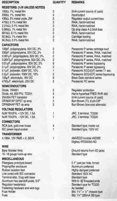
--above--PREAMPLIFIER PARTS LIST
Note that there are film de-coupling capacitors at each DC power feed pin on the op amps, which is important to reduce the possibility of noise and Oscillation. There is also a “pull down” resistor between the op amp output pin and the -12V DC power rail to produce a class A output bias of 2mA.
You could implement a more advanced bias system using an FET current source (Fig. 3). I suggest that all of the film capacitors and metal resistors used in the amplifier’s RIAA/gain network be value matched with suitable meters, and that they have very good sonic characteristics.
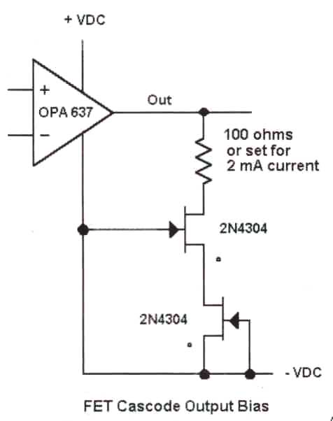
FIG. 3 FET Cascode output bias.
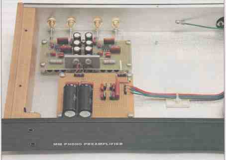
PHOTO 2: Front detail view of preamplifier circuitry.
The input section has a 200-ohm series resistor that forms a low-pass filter via the capacitor that sets the desired input capacitive loading for the phono cartridge. This configuration filters out frequencies in the MHz range that might contaminate the input signal to the op amp. If you live in a trouble some RFI area, the addition of a small ferrite bead on the input resistor leg might also be of help. The resistive loading is set to the specifications of the particular cartridge being used.
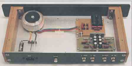
PHOTO 3: Rear overall view of preamplifier.
I did not install any sort of adjustable loading switches to avoid circuit complexities that might compromise the sonic performance. The out puts of the OPA 637 devices are directly fed to the output RCA jacks through 200-ohm metal film resistors. I chose not to use an output coupling capacitor to keep costs down and re duce sonic degradation, although it would be easy to add one as part of a first-order high-pass filter to block infrasonic frequencies. If you choose this path, it is wise to keep the filter turnover point well below 20Hz to avoid phase shifts that might color the sound, and select a very high performance capacitor.
In most cases, the components following the phono preamplifier have their own DC blocking input capacitors, and my op amps had only -50mV and +100V DC offsets for the left and right channel outputs. Note that the output offsets will be significantly higher if you use the OPA 604 op amps.
PHONO BOARD CONSTRUCTION HINTS
With many components closely situated on the phono board, it is a good idea to follow a clean, symmetric lay out that has been pre-planned. It is also important to try to produce low resistance/inductance ground return paths that have been separated out as much as possible. When fitting and soldering the various components and trace wires to the perfboard. It is very helpful to use an illuminated magnifier to ensure good solder joints and non-contact of adjacent solder pads. I used a fine gauge version of Wonder Solder that was very easy to work with.

---PROJECT RESOURCES---PARTS, etc.
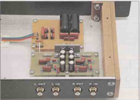
PHOTO 4: Rear detail view of preamplifier circuitry.
PREAMPLIFIER HOUSING
The biggest surprise about the preamplifier housing was the amount of time and effort that it required. I spent significantly more time with this part of the project than the circuitry and components that went inside! Originally I was going to find a commercial case to hold the components, but I decided against it due to the cost of obtaining one with enough space inside to allow keeping the toroidal transformer at a reasonable distance from the circuitry. If you want a good commercial aluminum enclosure, check out reference 2.
I constructed the case entirely out of aluminum, except for the side panels. The front and rear panels are made of 0.25” milled extrusions, while the bottom panel is of 0.125” sheet stock. The top panel is made of 0.030” sheet stock. I made the side panels with milled hardwood.
Almost everything is held together with stainless-steel sheet-metal screws that attach to the wood end panels, except for the front panel, which is attached with black oxide cap screws and nuts. All of the outer surfaces of the aluminum panels were fine-sandblasted as a preparation for spray painting, and the end panels received several hand-rubbed coats of polyurethane. I used some white press type that I had on hand for the lettering, and over-coated the finished front and rear panels with Krylon clear matte spray as a protective measure. I added three vibration-isolating feet to the bottom of the case to finish up.
BREAK IN, TESTING, AND LISTENING
With a little help from my scrap parts box, I spent just $115 to complete the preamplifier, although I believe it would be possible to buy all materials for $150 or less. A higher-performance version (even better RIAA components, regulators, and so on) might run $200. Now the task was to break in the unit, test a few parameters, and maybe even listen to it!
I had no desire to play records for hundreds of hours to properly break in the piece, so I ran a series of very low level signals into the pre-amplifier while loading the outputs with 10k-ohm resistors. I later located a specially produced CD with RIAA-equalized broadband noise that was ideal for such a break-in procedure.
When the break-in was completed, I decided to run a few tests on the pre amp to check aspects of its performance. One test involved measuring the 60Hz hum level in each channel relative to a 4mV input sine wave at 1kHz, which matched the output of my cartridge at a 5cm/sec recording velocity (0dB). This produced a margin of about 73dB, which you could improve by either adding shielding material around the transformer/power supply or moving it farther away from the active circuit board.
The hum level was never an audible problem, even though my transformer is only a bit over 6” from the main circuit board. Another test involved injecting very low level white noise into the preamplifier and verifying the RIAA playback curve characteristics. Finally, I verified the 44dB gain level at 1kHz.
The big question is how the unit sounds, given its very low cost and simplicity. All of the impressions that Twill impart are after the unit had 300 to 400 hours of break-in, and a two- to three-day warm-up for listening. I used a Shure V15 series cartridge in a damped low-mass tonearm on a belt-drive turntable for all listening.
I was very pleasantly surprised by the sonics from the start. The preamplifier quickly proved to be generally smooth and neutral, with a slight leaning toward the warm side. It produced a very nicely defined soundstage that could be very wide and fairly deep when the recording had such characteristics. It also had very good detail resolution and transparency.
I was particularly pleased with how well it reproduced instrumental sounds with convincing body and dimensionality. Delicate high-frequency sounds from harps and triangles seemed to float in the space behind my speakers, with very clean and natural transient attacks and decays. The preamplifier was also easily able to reproduce the many sonic recording differences (and shortfalls) of some of my records.
In sum, I believe that this unit offers a level of performance that is far beyond the price of construction, and that would easily embarrass many commercial solid-state phono preamplifiers that cost much more. If you are interested in getting into vinyl play back, do yourself a favor. Build this low-cost preamplifier and save your hard-earned dollars to purchase a better turntable and cartridge!
[The discussion above is adapted from an article, Jul 2004, outlined in xyz ]
... and this: All-JFET MM/MC Phono Preamp, Part 1 (June, 2005)