By Erno Borbely
This distinguished veteran of the audio design wars presents an interesting tutorial on phono preamps-followed in Part 2 by details of his latest high-quality, low-cost unit.

PHOTO 1: The phono preamp.
In the article “A Moving Coil Pre-amp, Part 1 ”, I covered basic noise theory and noise in audio amplifiers in de tail. Please read that article, because I will be giving you only a simplified description here. The article has a detailed treatment of the noise issues in phono preamps.
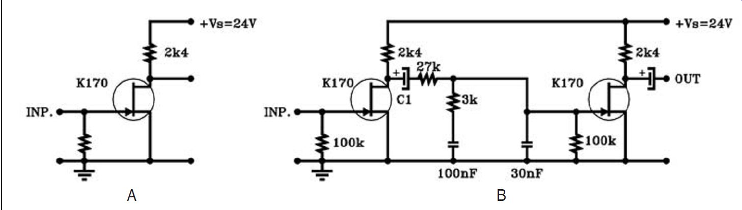
FIGURE 1: Common source amplifier.

FIGURE 2: Paralleling JFETs reduces the input noise.
The majority of pickups fall into two categories: moving magnet (MM) and moving coil (MC). MM pickups have a typical output of 5mV, while the MCs feature 0.5mV at 5cm/sec lateral velocity. There are MCs with lower output.
(I believe the old ORTOFON MC2000 was one of the lowest at 0.05mV!)
The high-output MCs are close to the MMs in terms of output, and you can use the normal MM input for these. MMs usually need a gain of 30-40dB and normal MCs 20-30dB more.
Of course, the extra gain needed for the MCs can be supplied with a transformer that has the proper turns ratio. There are a number of suitable transformers on the market, ranging from about $60 to >$10,000. The transformer has the advantage of providing the gain without adding noise to the signal. However, the transformers also have disadvantages, mainly in terms of distortion and limited frequency range.
I am not a transformer designer; consequently, I am always using active devices also for MCs.
The major challenge in designing phono preamps is the dynamic range, which is the difference between the lower limit--i.e., noise floor of the amplifier-and the upper limit, which is the clipping level of the amplifier. In a well-designed amplifier the noise is determined by the noise of the input stage and is usually specified as the equivalent short circuit input noise.
If you want this noise to be, say, 80dB below the normal output of 5mV of an MM pickup, then the equivalent short input noise must be 5mV/10000 =0.5µV. This is usually easy to achieve, even with tubes. However, in the case of an MC pickup with 0.5mV output, the equivalent short circuit input noise must be 0.5mV/10000 = 0.05µV (50nV!). This is much more difficult to achieve, as we will see later.
Of course, it's not just the amplifier that generates noise; all resistors are doing the same. In fact, the pickup it self can be considered a resistor that generates its own noise. The noise voltage generated by a resistor is given by the formula:
en = v(4kTR?f) where:
en is the RMS noise voltage in volts k is the Boltzmann constant (1.38 ×10^-23 joule/degree K)
T is the room temperature in kelvin (300°K)
If is the noise bandwidth in Hz (20000Hz)
R is the resistance in ohms.
If you have an MC pickup with an ohmic resistance of, say, 50 ohm (I have chosen the 50 ohmarbitrarily, MCs come with 10-50 ohm), then this pickup will generate a noise voltage of 0.128µV, or 128nV, in the audio frequency range. So you see that both the source--i.e., the pickup-and the amplifier contribute to the overall noise you hear.
Assume that you connect this 50 ohm pickup to an amplifier that has an equivalent short circuit input noise of 125nV. The total input noise will be v(1282 + 1252 )= 179nV, and the signal-to-noise ratio is 0.5mV/179nV = 2793x, which is 69dB. There is nothing you can do about the first term, the noise generated by the pickup, but you can certainly do something about the noise of the amplifier by designing a lower noise input stage! The lower its noise, the less it contributes to the overall noise.
If you look carefully you notice that the pickup and the amp contribute about the same amount of noise in the above example--i.e., the amp behaves as though it was also a 50 ohm resistor. You can, in fact, characterize the noise behavior of the amplifier with its equivalent noise resistance (Req.). As you will see, this is convenient for calculating the noise of the phono preamp, because the active devices--i.e., the tubes, transistors, and JFETs-can all be described by their equivalent noise resistance. Of course, you (or at least me!) are only interested in how the JFETs behave in this respect, but for the sake of peace with the tube and bipolar fans, I will also mention their devices in comparison!
A SIMPLE MM PHONO PREAMP
The basic amplifier that you can use for amplifying low noise signal is the common source amplifier, which I described in detail in Part 1 of the JFET articles.
Figure 1A shows the simple JFET stage without the source resistor, because I want to show what the source resistor does in terms of noise. The K170 JFET has an equivalent noise of 0.95nV/vHz, which over the audio frequency range is 134nV. This is the same as the noise of a 55 ohm resistor. For comparison, the discontinued K146 JFET was specified at 0.75nV/vHz, meaning an equivalent noise resistance of 34 ohm. The ROHM bi-polar transistor 2SD786 had 0.6nV/vHz, which is 21.3 ohm.
Triode tubes can also be represented by their equivalent noise resistance, which is 2.5/gm, where gm is the trans conductance of the tube in mA/V at the operating point. The ECC88/6DJ8 has a transconductance of 12.5mA/V at 15mA anode current and the Req = 2.5/12.5ma/V = 200 ohm. The 5842 and the WE417A tubes can be operated with a gm = 25mA/V, which will result in Req = 100 ohm . The 3A/167M, the WE437A, and the Russian 6C45p can produce, with approximately 40mA anode current, >40mA/V, thus bringing Req down to about 55 ohm. This is very close to what the K170 JFET does.
Coming back to the common source amplifier of Fig. 1A, the equivalent short circuit input noise of this stage is 134nV. A normal MM pickup has an equivalent ohmic resistance of about 600 ohm , which generates a noise voltage of 445nV. In this case the noise of the pickup dominates and the amp noise has little influence on the overall signal-to-noise ratio.
Of course, the picture is different if you want to use this simple stage with MC pickups. Assuming again an MC with 50 ohm resistance, the self-generated noise is 128nV. The amp is generating 134nV. Total noise is v(1282 + 1342)= 185nV.
The signal-to-noise ratio with a normal MC pickup will now be: 0.5mV/ 185nV = 2700x, which is only 68dB. The RIAA characteristic also helps a few dB due to its HF rolloff. But being a low-noise freak, I wouldn't consider this adequate for MC preamps.
A customer sent me the schematic of a simple two-stage phono preamp, which he found on the Internet (Fig. 1B). It uses two identical stages with K170, both operated at Idss = 5mA, with passive RIAA equalization between the stages. Each stage has a gain of gm × Rd, where gm is ˜30mA/V at Idss = 5mA and Rd = 2k4. The gain per stage is about 70×, or 37dB, which means a total gain of 74dB. The insertion loss of the passive equalization network, due to the 100k gate resistor of the second stage, is about 22dB at 1kHz, so the effective gain is about 52dB. This is a bit too much for an MM, but marginal for an MC. I have also seen a version with Rd = 5k1, which gives you a few dB more gain.
I hooked up the circuits in Fig. 1B to check out the performance. First, I measured the noise and distortion in the input stage only. The input noise was 137nV over a 30kHz bandwidth, so the equivalent noise resistance was actually less than the data sheet value of 55 ohm. The distortion was dominated by second harmonics: it was 0.88% at 1V RMS/1kHz and 2.5% at 3V/1kHz.
This is to be expected of a single stage K170 without a source resistor.
You could reduce this by using a source resistor as I have shown3, but since the source resistor is added in series to the equivalent noise resistance, it will increase the noise of the input stage [1].
A 50-ohm source resistor would reduce the THD by almost 6dB, but the equivalent noise resistance would increase to 55 + 50 = 105 ohm, which would result in an input noise of 186.5nV. The signal to-noise ratio with a 50 ohm MC pickup would be reduced to 66.8dB.
Next I hooked up the whole circuit as shown in Fig. 1B.
I measured a total gain of 50dB at 1kHz. Overall distortion was reaching 1% at 1.4V RMS/1kHz.
RIAA showed a 0.5dB rise at 10kHz, but was flat at the low end.
Thanks to the dominating second harmonics, this phono stage is probably very warm sounding. Indeed, a customer reported that this amp sounded very good with a DENON DL103 MC pickup in spite of the low gain, the second harmonic distortion, and the relatively high equivalent short circuit input noise.
DEVELOPING THE INPUT STAGE FOR THE STARTER KIT
Let's look at the input noise first. Just as paralleling resistors reduces the value of the resistors, the paralleling of JFETs reduces the equivalent noise resistance.
Paralleling JFETs with comparable gm reduces the resistance to half and the noise by approximately 3dB. I tested the circuit shown in Fig. 2, which I published in reference 3. Theoretically, four JFETs in parallel should have 6dB less noise than one JFET. However, you normally use a small source resistor with each to get better matching between the devices and/or to control the drain current, as shown in Fig. 2, so the equivalent noise resistance of each is 61.8 ohm. The four in parallel are then 15.45 ohm, and the input noise drops to about 72nV. I believe Nelson Pass is using this input stage in his DIY phono stage, albeit with 22 ohm source resistors, which increases the equivalent noise resistance and the input noise a bit. Note that the input capacitance also increases 4×, but it is not important here due to the low source impedances in phono preamps.
Paralleling the JFETs solves the noise problem, but does very little for linearity. This four-JFET circuit is a bit better than the single JFET in Fig. 1A due to the higher supply voltage: it's 0.32% at 1V RMS/1kHz and reaches 1% at 3V RMS/1kHz.
If you remember my priorities from the first part of this series (March '05 xyz) 4 they are low noise, inherent linearity, and DC coupling. This circuit fails on the second and third of these priori ties. I developed a line amp, based on complementary differential circuitry.
I mentioned that I use that topology in most, if not all, of my amplifiers.
The “if not all” means that I also use the single ended complementary topology in some of my amps. In fact, I use both in this two-amp phono preamp, but the single ended topology offers lower input noise than the complementary differential circuitry, so I use that for the input stage.
The complementary differential circuit is used for the second stage.
Figure 3A shows the four-JFET single-ended complementary circuit that was published in reference 5. Its linearity is orders of magnitude better than the single JFET circuit. O.L. THD is 0.032% at 1V RMS/1kHz and reaches only 0.4% at 10V RMS/1kHz! This topology works fine for an MM-only input stage, but it requires a circuit upgrade for real low noise operation. Figure 3B shows the low noise topology. I have doubled the input stage, making it equivalent to the four JFET circuit shown in Fig. 2 in terms of noise resistance.
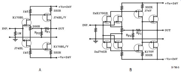
FIGURE 3: The basic four-JFET circuit and its upgraded version for low-noise application.
However, as you will see later, the feedback resistor(s) also contribute to the equivalent noise resistance, so that must be made as small as possible as well. Consequently, I added a complementary source follower to the output to be able to use low value feedback resistors. Granted, this is no longer a one-JFET circuit, and you will find very little of the second harmonic distortion in it. However, you will find low noise, good inherent linearity, and you can also use it without capacitors in the signal path. With the background material presented here, Part 2 will look at the complete phono preamp.
-- xyx
About the author: Erno Borbely received an MSc degree in Electronic Engineering from the Norwegian Institute of Technology, University of Trondheim. In the 60s he worked as a design engineer for the Norwegian Broadcasting Corp., developing studio equipment, both in tube and in semiconductor technology. In 1969 he moved to the US and worked for David Hafler at Dynaco. Mr. Borbely was named Director of Engineering for Dynaco in 1972. He developed the cascode output stage for the Stereo 400 power amplifier, and the Dynatune circuit for the FM5 FM tuner, for which he received a US patent. In the '70s he worked at Motorola Semiconductor, developing power amplifiers, low-noise preamplifiers, and FM tuners. Some of this work was put to good use when he joined the David Hafler Company in 1978 as Director of Engineering. Mr. Borbely developed the DH101 preamplifier and the DH200 power amplifier, which was the first to use MOSFETs in the US. From 1980 until 1997 he worked for National Semiconductor in Germany as its Technical Training Manager. In 1984 Mr. Borbely and his wife Irene started Borbely Audio, which sells high-quality kits to end-users. Since 1982 he has been publishing his de signs in Audio Amateur publications. In the last several years he has developed a line of all-FET audio amplifiers. Besides the kit business, he is designing audio products for OEM customers. Mr. Borbely's web page address is www.borbelyaudio.com and his e-mail address is erno@borbelyaudio.com.
References
1. Erno Borbely, “A Moving Coil Preamp Part I, ” The Audio Amateur, 4/86, p. 7. Part II 1/87, p. 30.
2. Pete Millett, “Moving Coil Phono Cartridge Transformers, ” May '05 audioXpress, p. 58.
3. Erno Borbely, “JFETs: The New Fron tier, Part 1, ” Audio Electronics, 5/99, p. 30.
4. Erno Borbely, “Starter Kits, Part I: EB 604/410 All-JFET Line Amp, ” audioXpress, March 2005, p. 9.
5. Erno Borbely, “The All-FET Line Amp ” audioXpress, May 2002, p. 28.
[The discussion above is adapted from an article, June 2005, outlined in xyz ]
Also see: