By B. F.
The author's latest series of horn-loaded cabinets is dubbed the Double Reverse (DR) line and is guaranteed to generate lots of interest.
I read Louis McClure's "Exponential Mid-Range Horn" articles (SB 7/99 and 8/99) with great interest. It's nice to see someone else challenging prevailing notions about horns.
For those of you who missed these articles, McClure built two midrange horns of similar length and mouth area, but with differing throat sizes and taper rates. The nearly identical response curves of the two horns defy traditional theory. Listeners' very different perceptions of the sound quality of the two horns, despite similar response curves, were more puzzling to McClure. He finished his experiments with perhaps more questions than answers.
I found his results confirm my own theories that the passband of a horn is mostly a factor of its length, efficiency is decided by mouth area, and that a tighter throat will give better high-frequency loading. While the passband and efficiency of McClure's two horns are very similar, the smaller throat version has a decided 6dB hump between 500 and 800Hz. If you'll recall the Fletcher-Munson curves, this is where the human ear is most sensitive. With a peak in that area I would expect it to sound harsh, as McClure described, especially when not sonically counterbalanced by any fundamental tones below 200Hz. How curious it is that those frequencies we are most sensitive to are also those that grate the most on our nerves, causing us to desire more and more bass.
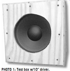
The quest for bass brings me to my own experiments in throat design. In minimizing throat sizes for better midrange loading, I found that smaller throats also result in lower fB. To better understand the relationships between throat size and fB, I built a 1ft^3 test box housing a cheap 10” driver (Photo 1). To this box I attached a horn.
Unlike McClure's magnificently constructed horns, however, my construction techniques came straight from the "Red Green Show": cardboard and duct tape (Photo 2). I charted the resonant frequency of the unaltered box and a variety of horn configurations. The results are displayed in Table 1.
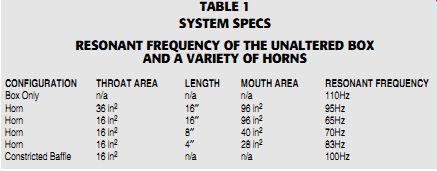
TABLE 1 SYSTEM SPECS RESONANT FREQUENCY OF THE UNALTERED BOX AND A VARIETY OF HORNS
PHOTO 1: Test box w/10” driver.
----------------
ABOUT THE AUTHOR
Bill Fitzmaurice (BA., University of New Hampshire) has been a professional musician since 1966 and has been constructing instruments, amplifiers, and speakers for just as long. As a resident of Laconia, NH, since 1981, he spends his winters skiing, his summers playing golf, and his weekends playing electric bass and running sound for the "L.A. East" rhythm and blues band, of which he has been a member for 15 years.
Owner of L.A. East Recording Studios, he has also managed to find time to write an adventure novel. Fitz maurice is the author of "Loudspeakers for Musicians" and over 30 magazine articles dealing with speakers and electric instruments.
-----------------------
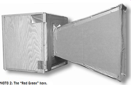
PHOTO 2: The "Red Green" horn.
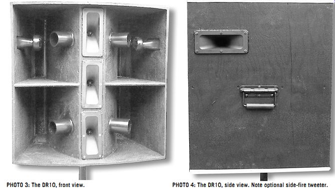
PHOTO 3: The DR10, front view.
PHOTO 4: The DR10, side view. Note optional side-fire tweeter.
The results were a revelation to me. Obviously, the size of the throat is more important than either the length of the horn or the area of the mouth in lowering the system resonance. I was most surprised by the constricted baffle configuration, which was simply a plate with a hole in it, placed over the driver opening in the baffle. Why did this cause a 10Hz drop in the box resonance? I realized that the space between the driver cone and the constricted baffle opening became a resonant chamber, turning the closed box into a simple dual-chamber reflex box.
How does this relate to horn design? Consider a horn/reflex cabinet with a desired low frequency cut-off at 40Hz. Maximum efficiency is achieved if the driver/horn resonance (the fS of the driver after mating it to the horn, but prior to enclosing the rear of the driver) is close to 40Hz. If the driver/horn resonance is significantly less than 40Hz through use of too small a throat, then mid-bass performance will suffer.
On the other hand, too large a throat will result in poor midrange loading, as well as too high a system resonance.
Clearly, the proper size throat opening is critical for maximum performance. With that fact in mind, I spent more time working on the throat configuration of my latest design than on any of my previous cabinets. With the results I achieved I think I am on the right track.
[Note: I have not seen described a term which denotes the resonant frequency of a driver mated to a horn while the rear of the driver is exposed to free-air, so I have coined one: fS(h)].
HORN DESIGN
The impetus for this cabinet was an inquiry from a manufacturer interested in my Snail folded horns for bass, keyboard, and PA. [For a collection of the author's work with Snail folded horns, see SB back issues and Loudspeakers for Musicians, available from Old Colony Sound Lab, 888 924-9465 - Eds.] He had three design requirements.
First, the design needed to be compatible with molded construction, most likely fiberglass. Second, the design must be suitable for medium-priced drivers, rather than the premium EVs and JBLs I'd used in most of the Snail designs. Last, the design needed to work full-range as a two way system, preferably using piezo drivers for the high end. (It also wouldn't hurt if it blew away anything else currently avail able on the market.) The result of my efforts to meet these requirements is the 10 ohm loaded DR10, the first in a series of cabinets using drivers from 8 to 15 ohm (Photo 3). It can be duplicated in fiberglass, or another molded construction method, by producing sub-assemblies (the throat horn, the mouth horn, and the exterior shell), which would be bolted together. To make cheaper drivers feasible, the cabinet is larger than a Snail designed for a ten would have been.
This allows a longer horn path and larger mouth for better efficiency over a wider bandwidth; the mid-line driver-equipped DR10 outperforms the smaller Snail and Mid-Ranger, despite their being loaded with premium twelves.
The mouth opening is square, which is more efficient than a rectangular one. The throat section is subdivided to minimize its cross-section for better mids, while the mouth is subdivided to provide bracing between the horn and the exterior shell.
Unlike traditional designs, the horn taper is not a constant formula from throat to mouth.
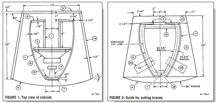
FIGURE 1: Top view of cabinet.
FIGURE 2: Guide for cutting braces.

PHOTO 5: Cutting angled piece of plywood to modify panel cutting jig.
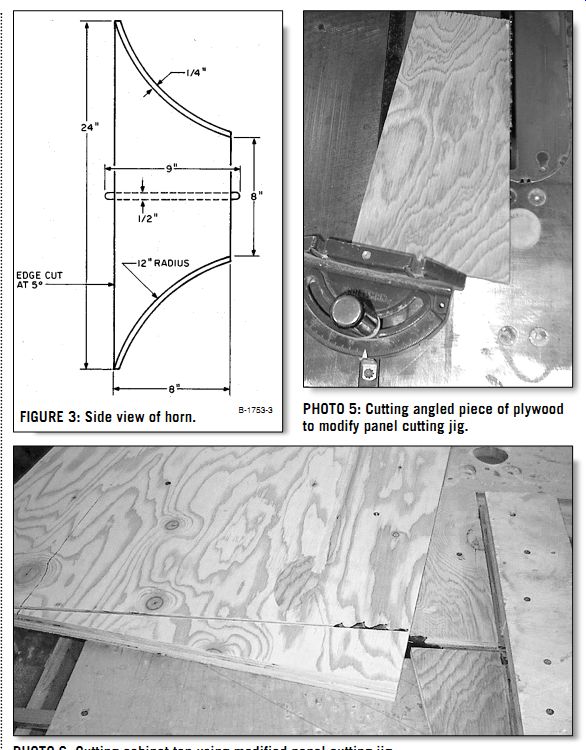
FIGURE 3: Side view of horn.
PHOTO 6: Cutting cabinet top using modified panel cutting jig.
Waves from the driver first pass through a rapidly flaring midrange horn, then reverse direction to pass through the mouth horn, which has a slower flare rate. In other words, this cabinet consists of two separate and distinct horns, which are coupled in series: a double horn.
Where the two horns join together, the direction of the wave path reverses, thus, the Double Reverse, or DR, horn.
Unlike the Snails, this cabinet does not have driver chamber ducts exiting into the horn throat. While that technique works well with shorter horns, doing so with a longer horn drives fB too low. In stead, four ducts exit the driver chamber very close to the horn mouth, allowing for easy and precise tuning of the system. As in the Snails, all interior reflectors are round to minimize phase cancellations.
The cabinet's exterior shell also has a trapezoidal shape. I included this feature strictly for cosmetic value, since I once overheard a fellow musician incorrectly attributing the quality of a commercial cabinet to its trapezoidal shape. A trapezoidal shape in and of itself indicates nothing of a speaker's worth, but if it sells, then why not do it ? The cabinet also features an arced leading edge at the top and bottom. This will, in theory, make the box work better, but I included this feature primarily because it looks cool.
The tweeter section consists of three Motorola KSN 1176 piezos in a vertical array, for maximum horizontal dispersion. These cut out below 2.5kHz, but the response dip between the woofer and tweeters is not severe, since the woofer is effective to 2kHz. Different drivers could eliminate the dip entirely. The woofer I used-because I had it on hand-is an Eminence 10” cast-frame MI driver that is no longer being produced. Its fS of 55Hz, QTS of .25, VAS of 1.85ft2, and SPL of 98dB are fairly typical of medium-quality MI tens.
In choosing a driver for this project, stay away from premium drivers such as JBL or EV (which have very large mag nets), since they might not fit into the driver chamber. A magnet weight between 40 and 80 oz will do nicely. The most important spec is the fS; do not use a driver with fS less than 50Hz or more than 60Hz. The prototype also features option al KSN 1176s on each cabinet side for side-stage projection. Note that these are aligned horizontally, since they provide better horizontal dispersion this way when used singly.
CONSTRUCTION
I constructed the cabinet for the proto type of ½” plywood, excepting horn sheathing ( ¼” plywood). You may use thicker materials for ease of joinery, but rest assured that additional weight is not necessary for strength. The self-bracing design may be lightweight, but it is rock solid.
Glue and seal all joints with construction adhesive, and secure them with 1¼” drywall screws driven through drilled and countersunk pilot holes. For thicker materials (I wouldn't recommend more than 5/8” plywood), use 1 5/8” screws. Note that all measurements are nominal, the exact dimensions being dependent on the actual thickness of the materials used. Don't try to cut parts much in advance of assembling them; actual part sizes should be double-checked using the previously-assembled parts as a reference.
Before starting construction, thoroughly examine all of the figures and photos.
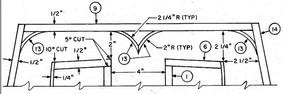
FIGURE 4: Cutaway view of throat reflectors.
Note that Figs. 1, 2, and 4 are variations on the same view; to include all the components in one view would be too cluttered. Figure 3 shows a cutaway of the throat horn. The optional side-fire tweeters (Photo 4) are not included in any of the figures, nor is any hardware shown.
As in all successful projects, you should understand what you're trying to build be fore you make any sawdust fly.
MAKING THE CUTS
The first step is to cut out the top and bottom (Fig. 1), which requires straight, accu-
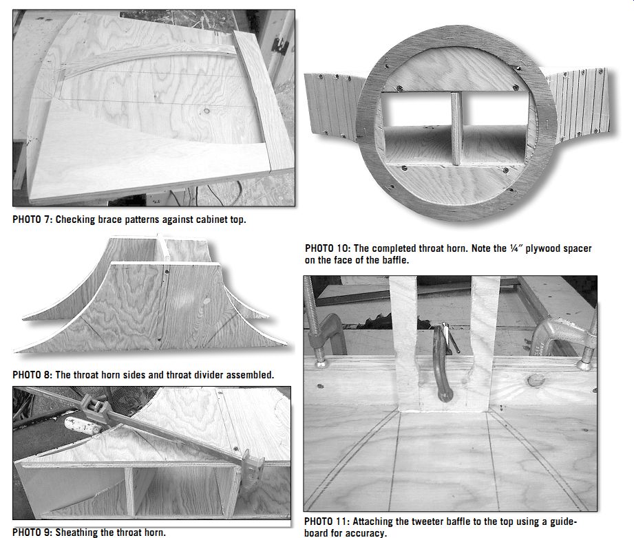
PHOTO 7: Checking brace patterns against cabinet top.
PHOTO 8: The throat horn sides and throat divider assembled.
PHOTO 9: Sheathing the throat horn.
PHOTO 11: Attaching the tweeter baffle to the top using a guide board for accuracy.
PHOTO 10: The completed throat horn. Note the ¼” plywood spacer on the face of the baffle.
rate 80° cuts (or 100°, depending on point of view), instead of the usual 90°. Doing this on a table saw is easy if you first cut two pieces of scrap plywood at a 10° angle, using your miter gauge (Photo 5). Screw these directly to your panel-cutting jig (if you haven't yet made one, do it now), al lowing you to feed a panel across the saw table at a perfect 80° angle (Photo 6). To ensure that the top and bottom are identical, first rough-cut two pieces of ply-
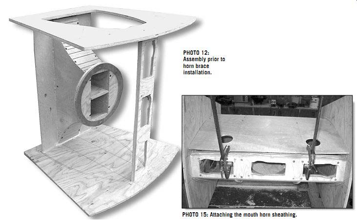
PHOTO 12: Assembly prior to horn brace installation.
PHOTO 13: View through the porthole.
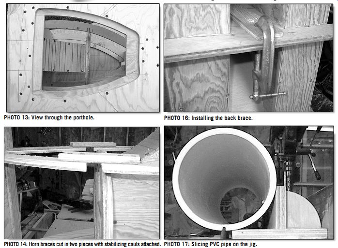
PHOTO 14: Horn braces cut in two pieces with stabilizing cauls attached.
PHOTO 16: Installing the back brace.
PHOTO 17: Slicing PVC pipe on the jig.
PHOTO 15: Attaching the mouth horn sheathing.
... wood slightly oversize, and then screw the two together with 1” screws. Now cut both pieces to finished size simultaneously. This trick is valuable anytime you need identical parts.
After cutting the top and bottom, draw the placement of all mating parts onto them (Figs. 1 and 2). You can draw the arcs with an oversized compass, a long plywood sliver with a drywall screw at one end serving as a pivot and ¼” holes drilled through the plywood at the required radius distances from the screw, through which you insert a pencil to draw the arc. Once the parts locations have been laid out, make the patterns for the horn braces, back brace, and side braces (Fig. 2), comparing them to the layout drawn on the top and bottom for accuracy (Photo 7). Note that the horn braces are cut to a 23¾” radius on both the inside and out side, so that, when cutting out a number of braces, the inner edge of one is the outer edge of the next. I made the proto type using ½” plywood for all braces, but this is one place where thicker materials, even 5/4 lumber, will make joinery easier without much of a weight sacrifice. Mark the cut line on the bottom piece for the driver access porthole, cutting it out using a saber-saw (starting with a plunge cut).
Next, lay out and cut the horn throat sides, which have a 5° angle on one edge (Fig. 4). Attach them to the throat divider (Photo 8). The divider extends ½” beyond the side edges; round both its ends over, either by sanding or routing. Using clamps and one or two plywood scraps, cut to 4 ohm wide, as temporary braces to hold the throat sides square precisely 4” apart, while attaching both the divider and the throat sheathing (Photo 9). The sheathing, cut from ¼” plywood, must be kerfed on the table saw with cuts about ¹/8” deep across the panel at about 1” intervals, which allows it to be easily bent to the arc of the sides. Cut the sheathing a bit longer than required, with the ends trimmed or sanded to exact size after assembly for a perfect joint with the baffle and cabinet assembly.
ACCOMMODATING THE DRIVERS
The baffle is a circle of plywood 11” in diameter through which is cut a 4 ohm× 8 ohm rectangular hole, centered on the baffle's axis. Attach a spacer ring of ¼” plywood to the baffle to prevent the cone edge from slapping the baffle in long excursions. Drill the baffle and insert four T nuts into it for driver mounting (using only every other hole on the driver) with
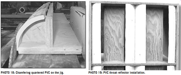
PHOTO 19: PVC throat reflector installation.
PHOTO 18: Chamfering quartered PVC on the jig.
... the holes aligned near the corners of the hole, not along the sides. Attach the baffle to the throat assembly, after sanding over the hole opening to eliminate sharp edges (Photo 10). Where the baffle meets the throat sheathing no screws can be used, so use plenty of adhesive for an air tight fit.
Cut the tweeter baffle to size, and then cut holes for the tweeters through it, equally spaced across its length. The cut angle for the tweeter baffle sides is 35°. If you use ½” plywood for the baffle, cut some extra strips of plywood at 35° angles as bracing blocks, which will later be attached to it. For thicker materials, additional bracing will not be necessary.
The holes for KSN 1176 frames measure 5 ¹/8 “× 2 ¹/8 “, but the driver element housing will not fit through holes of that size, so trim a bit of material, as required, from the holes to allow the drivers to fit.
Attach the baffle to the cabinet top. This (and all similar joints) is best accomplished by first drilling pilot holes through the top along the joint center and then clamping a straight guideboard to the top along the joint line.
Apply adhesive to the edge to be mated, and clamp the baffle to the guide board (Photo 11). Only when you are sure that the joint is perfectly aligned should you drill through the holes, using a pilot/countersinking bit, and screw the parts together. Using one drill for piloting and another for screwing makes this a fast and easy procedure.
Cut the horn plates to size, paying close attention to the angles of the edges (Fig. 4), and in similar fashion attach them to the top. When the cabinet bottom is complete, attach it to the assembly.
Trim and sand the throat assembly for a proper fit with the rest of the cabinet and secure it in place, again using no screws and plenty of adhesive where the horn sheathing mates the cabinet top and bottom (Photo 12).
Tracing from the patterns, cut seven more horn braces, for a total of eight, and one more side brace. Attach the horn braces to the assembly, with four attached to the top and bottom and the other four spanning from the sides to the tweeter baffle (Photo 13). On the bottom, use plywood to fill the gaps between the braces (Fig. 2), forming a mounting flange for the porthole.
Place the spanning braces about 6 ½” from the top and bottom. If placed too close to the baffle, they will interfere with accessing the driver attachment bolts; if too close to the top and bottom they will interfere with the ducts. Cut the two spanning braces closest to the porthole into two pieces to allow the driver frame to pass between them.
Use temporary cauls, screwed to the braces, to hold the braces in position until after the horn sheathing is in place (Photo 14). You may need to do some additional trimming to these braces, de pending on the size of your driver mag net. Do this now, making absolutely sure that you can fit the driver through the porthole and slide it into position on the baffle. Once the sheathing is in place further trimming is very difficult-which I can attest to from personal experience. Cut the bracing strips (for a ½” tweeter baffle only) to length and install them between the horn braces. Cut the horn sheaths to size. The radius of the horn is slight enough that kerfing here is not necessary, but check the plywood for its easier bending axis before cutting the parts.
Cut the sheaths a bit long, to be trimmed after installation.
The duct holes, 2 ½” in diameter, should be cut with a hole saw, which can tear up thin plywood when unsupported.
Drill these before installing the sheathing (with a supporting piece of scrap be hind the sheath to eliminate tear-out).
The centers for the holes are 4” from the leading edge of the sheaths and 4 ½” from the top and bottom; double-check to make sure the duct holes don't hit the braces.
Attach the sheathing first to the horn plates, then pull it into place with long clamps. At the same time, drive screws every four inches or so (Photo 15). Once you have attached both sheaths and the adhesive has dried, trim and smooth the joints with the tweeter baffle, and remove the cauls on the braces.
Attach the back brace to the horn plates and throat divider, using a clamp and two pieces of scrap to align it with the throat divider while driving screws into it from the cabinet interior (Photo 14). The rounded edge of the throat divider serves as a trough for adhesive; after it has set, sand the joint smooth. In a similar fashion, clamp the side braces to the back brace while driving screws into them from inside the cabinet.
There is little room inside the cabinet, so these screws must be driven by hand (God forbid!), using a short shaft screw driver or a small ratcheting driver. This joint is likely to be ragged, and you probably will only be able to get a couple of screws into it, so use plenty of adhesive on the joint to seal the gaps. After the adhesive has set, install the cabinet sides.
WORKING WITH PVC
Cut the throat reflectors (Fig. 4) from 4 ohm Schedule 40 PVC. This stuff is very easy and safe to work with if you use it properly. First, make a cutting jig (Photos 17 and 18). Screw the PVC right to the jig using drywall screws. Then push the jig through the saw, using the saw rip guide to set the proper distance from the blade. PVC will bind on a blade if cut all the way through, so set the blade height to cut not quite all the way through; finish the job with a utility knife.
You need to quarter a 24” piece of PVC; after quartering, screw the pieces to the opposite side of the jig for chamfering.
You can use a toothed blade for both cut ting and chamfering, but an abrasive blade is safer and cuts cleaner, as well.
After chamfering one edge of the PVC, remove it from the jig and reattach it to chamfer the remaining side. Use a T square to check the angle of the second cut. You'll need two pieces cut at 90° angles, and two at about 100° angles, to fit the 10° flare of the cabinet sides with respect to the back.
Cut the PVC reflectors to length to fit the mounting locations. Use a hot-melt glue gun to attach the 90° pieces to the cabinet, back-to-back, where the throat opens into the cabinet, and the 100° pieces where the sides will meet the back (Photo 19). Cut the back piece and install it, using plenty of adhesive where it meets the PVC reflectors; do not drive screws there. If you plan on putting your jack on the cabinet back, cut a hole in the back for it. Cut another hole for the wire to the driver through a horn plate, running a piece of wire through that hole and sealing it with hot-melt glue before attaching the back.
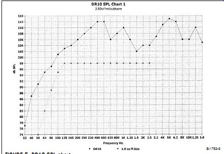
FIGURE 5: DR10 SPL chart.
ASSEMBLY
Using a sander and/or router, trim all exterior joints flush and apply your finish of choice. If you plan to attach the porthole with screws, put it in place and drill pilots for them, about a dozen or so. Alternately, you can drill for bolts and install T-nuts on the bottom.
Vacuum the cabinet clean and install the woofer. Because the mounting bolts are difficult to access, it's best to use either Phillips or Allen head bolts, which are easier than slot-head bolts to drive by feel. Again, a short-handled driver or a small ratchet driver works well.
Install the tweeters, wiring them to each other in parallel, and then wiring them in parallel to the woofer. They...
TABLE 2
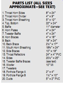
PARTS LIST (ALL SIZES APPROXIMATE-SEE TEXT)
...should be wired in-phase with the woofer.
If you decide to use side-firing tweeters, cut holes for them in the cabinet sides and install them, drilling holes through the horn sheath to wire them up, and sealing the holes with hot-melt glue.
The ducts (for a driver fS of 55Hz) are 5” lengths of 2” PVC; install them now, using hot-melt glue to seal them in place.
Be careful not to push the ducts in too far because they will hit the tweeters. Spray paint the ducts to color-match the cabinet finish, and caulk the tweeter frames tight.
Fully stuff the cabinet with at least a pound of poly-fill, being sure to leave no voids except directly behind the woofer and near the duct entryways. For PA usage this box should be pole-mounted for proper projection, making the port hole cover a viable location for both the jack and the pole mount. Alternately, the jack may be side mounted. This will re quire a hole through the horn sheathing (caulked tight of course) for the wire.
If you're using a pole-mount top hat, the center of gravity of this box is almost precisely in the cabinet middle. Install the top hat and jack, caulking them air tight. Solder the wiring to the drivers.
Rim the porthole flange with ½”-thick neoprene weather-stripping and install the porthole cover. You may attach handles using bolts and T-nuts, but I used screws, driving them through the sides into the side braces. While reasonably light at about 50 lbs, the bulk of this box will make casters a worthwhile option; at tach them with bolts and T-nuts. Now plug it in and rock.
PERFORMANCE
If this is your first horn-loaded cabinet you'll be amazed at how loud it is without needing a mega-watt amp to drive it. If you're a bass player you may feel (not just hear, but actually feel) low tones that you've never experienced before. If you're used to playing keyboards through guitar amp speakers, be prepared to hear those tweeters cranking out harmonics you never knew your keys had in them, as well as low tones reminiscent of a pipe organ. Be it on bass, keyboards, or PA, you now have one of the best cabinets available anywhere, at any price, al though this cabinet can be built as de scribed for less than $175 per copy.
To back up these statements, look at the SPL charts (Figs. 5 and 6). In Fig. 5, the dotted trace is the projected response from the same Eminence woofer in an optimally tuned T/S box (and keep in mind that this driver is considerably better than most OEM drivers). On average, SPL from 125Hz to 2kHz is about 98dB; with 150W input, output is about 118dB. On PA, this would work for a small club, but that's about it. For electric bass, the 40Hz to 80Hz (the first octave on the bass) average SPL is a meager 78dB. To get 108dB output, a conservative requirement for bass, would require over 1kW. Your amp probably doesn't have that much juice available, but that's a moot point, since even four tens couldn't take that much power. Using two tens wired in parallel, or four wired as series/parallel pairs, will produce another 6dB sensitivity, but 84dB sensitivity still doesn't cut it.
The only way you can get the bottom you desire using tens in a T/S box is to use eight of them and hope that your amp is big enough. Now look at the solid trace, the DR10.
With average SPL from 125Hz to 2kHz at 107dB, a 150W amp will give 128dB output with headroom to spare. In PA, a pair of these will easily handle a 500-seat room. For the bass player, on average, SPL from 40Hz to 80Hz is 92dB; most T/S boxes with eighteens can do no better.
108dB output requires less than 50W. If you love the tone of your old blackface Fender Bassman, but it just isn't loud enough, this cab will cure the problem.
On keyboard, the combination of high sensitivity and wide bandwidth gives performance that no commercial keyboard cabinet can approach.
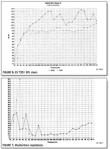
FIGURE 7: Woofer/horn impedance.
FIGURE 6: EV T251 SPL chart.
Speaking of commercial cabinets, look at Fig. 6. Here the dotted trace on the chart is for a commercial 2-way cabinet using a 15” woofer and horn loading on the mids and highs, the renowned EV T251. It is close to the DR10 in size (about 7ft^3), though at 78 lbs, it weighs over half again as much. Typical of commercial cabinets, it has an average SPL of 98dB. It will handle 400W RMS input, and you'll need it, for even with over twice the input power it still lags behind the DR10 in output by 6dB. That means you'll need two of them to match one DR10, plus 800W to drive them. Oh, and they retail at over a grand apiece, though you can find them discounted at around $700--what it will cost you to build four DR10s.
DISPELLING MYTHS
Like McClure's midrange horns, the DR10 proves that some assumptions about horns don't ring true. On the subject of throat size, a popular formula states that St = .8 × fS × QES × VAS. For the subject Eminence driver this would result in a throat of about 22 in^2. Is this correct ? I beg to differ.
The dotted trace in Fig. 7 shows the impedance of the woofer/horn before sealing the box. The target fS(h) of 40Hz is achieved with a throat of about 30 in^2. A smaller throat would result in an fS(h) lower than 40Hz, which would give a response dip in the second octave (80 160Hz). Better high-frequency performance would doubtless accompany a smaller throat, but since we're trying to maximize the bass, the point again is moot. This throat formula may be accurate when used in a compression horn, where the driver is in a sealed chamber small enough to drive the fB up to the desired frequency, but as far as a horn/reflex combination is concerned it does not work. I do not have a formula to replace it. I arrived at the 40Hz fS(h) only through a lot of experimentation with a lot of plywood.
A formula to predict throat size for a given fS(h) would need to include not only the driver parameters but also the horn taper, horn length, mouth size, and the volume of air between the cone and baffle. To calculate it may be impossible.
This could be one area where empiricism will continue to rule.
Speaking of formulas, I recall a reply to a reader's letter a few years back questioning how to tune the reflex section of a horn/reflex combination. The reply was that such a combination had not been modeled. It has now. I direct you again to the impedance chart in Fig. 7.
After sealing the box, I tuned the cabinet with the duct length that gave the highest SPL at 40Hz without degrading performance at higher frequencies. The result is seen in the solid trace, with an impedance null at 40Hz flanked by peaks above and below it. This is classic ducted port tuning.
Another impedance null occurs at 125Hz, representing the Fh of the horn (the beginning of the horn passband), followed by a peak at 160Hz that represents the ¼ wavelength resonance of the horn mouth. Nominal woofer impedance then settles in at 9 ohm, while the three tweeters paralleled never go below 18 ohm. Should you use a driver that differs significantly from an fS of 55Hz, measure for fS(h) with the porthole cover off, and then adjust the duct lengths for an Fb that matches it.
Like the Snails before it, the DR10 gives high frequency performance that folded horns are not supposed to deliver.
Louis McClure's article refers to the "mass rolloff" of his bass horn, which be gins at 390Hz. Not having seen his de sign, I cannot comment on why his bass horn rolls off at 390Hz, but I can state un equivocally that mass rolloff is a myth.
Calculated from a formula derived by Keele ("Low Frequency Horn Design Using Thiele/Small Driver Parameters," AES Reprint #1250, 1977), stating that Fhm = 2fS/QES, mass rolloff for the Eminence driver in the DR10 should occur at about 407Hz; clearly, it does not.
I certainly would not challenge the credentials of the redoubtable D.B. Keele, but when it comes to denying the existence of mass rolloff, I have cooked the pudding in which the proof does lie.
Keele was wrong; the rolloff of high frequencies in a folded horn has no connection with the driver T/S parameters and is purely a result of out-of-phase reflections that occur within the horn. This can be addressed through careful throat design, keeping horn bends to a minimum, and rounding all bends. I plan to experiment further to see whether alternate construction methods can achieve even broader bandwidths and flatter response from folded horns-based on my results with the DR10 I think that the outlook is very promising.
I'm forwarding this article to my potential manufacturer, to see how he next wishes to proceed. Be assured that, what ever the result, you'll see it here on the pages of audioXpress. In the meantime, don't wait to buy one of these babies.
Based on what manufacturers are get ting for T/S boxes, I'd expect the commercial version to go for at least $800. Head on out to your workshop and build your own (Table 2). You won't be disappointed, I guarantee.
Also see: