In response to a reader request, this author adapted a previously published
tilt control design for tubes.
By ME.
In a letter published in the 6/99 issue of Glass Audio [1], Aaron Freed expressed interest in a vacuum tube version of Reg Williamson's tilt control. I recently built a prototype of such a circuit, and I thought it might be of general interest to Glass Audio readers, including Mr. Freed.
FILTER CIRCUIT
Figure 1 shows the IC op-amp version of Mr. Williamson's circuit, which is taken from Fig. 7 of Williamson and Watling's article on their "Back to the Future" preamp. [2] This circuit allows you to tilt the audio frequency spectrum up or down with variable slope around a fixed central frequency, which is about 950Hz in this case. With the potentiometer in its center position, the frequency response is flat.
Rotated in one direction, low frequencies are boosted, and high frequencies are attenuated by the same amount. Rotated in the opposite direction, high frequencies are boosted and low frequencies are attenuated. The maximum action of the control is limited to 6dB of boost or attenuation. The control can be taken out of the signal path by placing SW1 in the flat position, in which case the circuit has unity gain for all audio frequencies.
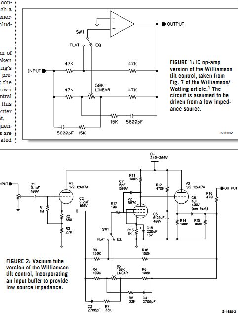
FIGURE 1: IC op-amp version of the Williamson tilt control, taken from
Fig. 7 of the Williamson/Watling article. FIGURE 2: Vacuum tube version
of the Williamson tilt control, incorporating an input buffer to provide
low source impedance.
1. The circuit is assumed to be driven from a low impedance source.
--------------
ABOUT THE AUTHOR
Scott K. Reynolds has a PhD in electrical engineering and is presently employed as an analog and mixed-signal circuit designer at a large computer-systems manufacturer.
He became fascinated with electricity in early childhood and learned about vacuum tube electronics from his father's WWII-era textbooks. By the time he was in high school, he was experimenting with his own amplifier circuits. Although his work now involves bipolar and especially CMOS transistors, he'll always like vacuum tubes better.
Reynolds lives in the New York City suburbs with his wife and seven-month old son.
--------------
This circuit is a member of a general class of filters known as infinite-gain single-amplifier filters. [3] It is also rather ingenious because it combines the functions of conventional shelving bass and treble controls in a single control with a minimum number of components. Don't be fooled by the simplicity of Fig. 1; this is quite a sophisticated tone control. If the tilt potentiometer has a calibrated scale, it is possible to control the amount of tilt down to a few tenths of a dB.
Infinite-gain single-amplifier filters get their name from the infinite (that is, very high) open-loop gain of the op-amp, and their design equations are based on the assumption of infinite gain. However, I've found that I obtain results very close to the calculated responses if the open-loop gain is 50 or higher. The tilt circuit will continue to work with still lower open loop gains, but the response becomes asymmetric about the center frequency, and I observe different amounts of boost and cut.
Since the positive input of the op-amp is grounded, it isn't necessary to have a true op-amp; any high-gain inverting amplifier with high input impedance and low output impedance will work as the active circuit element. Thus, it is easy to implement the circuit with tubes. As Mr. Williamson indicates, you must drive the circuit from a low-impedance source in order for the response to be symmetric.
TUBE VERSION
Figure 2 illustrates a vacuum tube version of the tilt circuit. Table 1 lists the parts and values. The circuit impedances have been scaled up from those in Fig. 1 to better match vacuum tube characteristics. A 12AX7 cathode follower (V1) provides a low impedance source to drive the filter circuit. A 5879 pentode (V2) provides the relatively high gain, and a second 12AX7 cathode follower (V3) obtains low output impedance.
The 5879 is a low-noise, medium-gain pentode originally used for microphone preamps. With the circuit values shown, it provides an open-loop gain of about 95 with low distortion. With the feedback circuit in Fig. 2 disconnected, I applied a 21mV RMS, 1kHz test signal to the 5879 grid and measured second-harmonic distortion of 0.19% at 2V RMS output. No higher-order harmonics were visible above the 0.08% noise floor on my spectrum analyzer.
The circuit in Fig. 2 will also work with out the cathode bypass capacitor C18, in which case the open-loop gain of the 5879 drops to 45 and the distortion (still second harmonic) rises slightly to 0.22% at the same 2V RMS output. High-quality NOS (new, old-stock) 5879s are readily available [4], but other tubes (either medium-gain pentodes or high-gain triodes) could also be used for V2 (with different circuit values).
The circuit in Fig. 2 forms a complete tilt control, but, as a line amplifier, it has two disadvantages: it inverts the signal, and it provides no closed-loop gain. Both of these shortcomings are remedied by the circuit in Fig. 3, which provides a non inverting gain of 3.2 (10dB). Table 2 shows the parts. It also adds another useful function, a second-order hiss filter with three selectable cutoff frequencies of 5kHz, 7kHz, and 10kHz.
MEASUREMENTS AND VALUES
In Fig. 4, I've plotted the measured frequency response of my prototype of Fig. 3 for four different settings of the tilt potentiometer (R5), as well as with SW1 in the flat position. All curves in Fig. 4 were taken with SW2 in the flat position.
The seesaw action of the control is readily apparent. Because of the limited gain of my vacuum tube "op-amp," the curves of Fig. 4 are not quite as symmetrical as they would be if the circuit were implemented with an IC op-amp, but the degree of symmetry I obtained is more than adequate. Figure 5 shows the measured frequency response of the hiss filter for each of its cutoff frequencies.
The circuits in Figs. 2 and 3 are both suitable for driving loads down to about 10k, but the output coupling capacitor C6 should be adjusted for best low-frequency performance. The 1µF value shown is suitable for loads down to about 50k. For 22k loads I recommend 2.2µF, and for 10k loads I recommend 5.1µF.
Solen makes low-cost poly propylene capacitors which are ideal for all coupling capacitors in these circuits.
The frequency-determining capacitors in Figs. 2 and 3 (C3-4 and C8-13) can be dipped mica or polystyrene capacitors with a 50V or higher rating. C7 and C19 can also be dipped mica, with a 500V rating. All resistors can be ½W unless otherwise noted.
Closed-loop distortion in the circuits of Figs. 2 and 3 is very low. At 2V RMS into ...
--------------
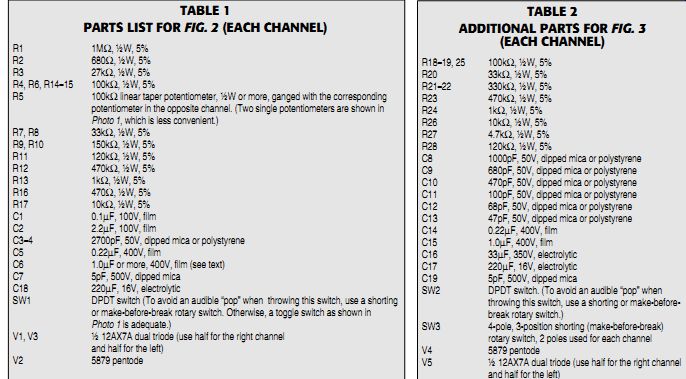
TABLE 1 PARTS LIST FOR FIG. 2 (EACH CHANNEL)
TABLE 2 ADDITIONAL PARTS FOR FIG. 3 (EACH CHANNEL)
-----------------
... 10k, total harmonic distortion is below the 0.08% noise floor of my spectrum analyzer, and intermodulation distortion is below the 0.06% noise floor of my IM analyzer. If you wish to drive resistive loads below 10k or capacitive loads above 1800pF (i.e., more than 60' of cable at 30pF/foot), or if you need output swings more than a few volts RMS into low impedances like 10k, you may prefer to try higher bias current in the output stage.
Output stage bias current in Figs. 2 and 3 is about 1.2mA. If you substitute a 12AU7 for V3 and a 22k 3W resistor for R14, output stage bias current will be about 6mA, providing five times the drive current. But there's no need to do this un less you really require high drive current.
In fact, I've found that the 12AX7 is a more linear cathode follower, as long as the current drive it provides is sufficient.
Before you commit to the complete line amplifier in Fig. 3, I recommend building a prototype of the circuit in Fig. 2 to see whether you like the action and sound of the tilt control. As Mr. Williamson says, the tilt control is very convenient for adding a bit of warmth to a recording that a recording engineer has made overly bright. You might call it a "warmth control."
CONSTRUCTION
I built my prototypes on perfboard, using PC mount sockets for the tubes (Photos 1-3). I inserted the components and tube sockets from one side of the perfboard, just as in printed circuit board construction, and wired the circuit on the back side of the board, using the component leads and short pieces of insulated wire. I often prototype simple circuits this way because it is more compact and less expensive than doing point-to-point wiring in a conventional chassis. I show a component placement diagram in Fig. 6, for those readers who wish to make a near identical copy of my prototype of Fig. 2.
For bench testing and listening evaluations, I mounted the perfboard (along with the controls and RCA jacks) on a grounded metal panel salvaged from an other project. Either this sort of metal ground plane or a fully enclosed grounded metal box is highly recommended to prevent noise pickup. For safety reasons, some type of enclosure is required to pre vent accidental contact with the high volt age nodes in the circuit! When you build your prototype, don't forget the frequency compensation components R16, C7, and C19, since they are necessary to prevent high-frequency instability under some conditions. The purpose of grid stoppers R17 and R26 is to re duce the chance of radio frequency interference; these should be mounted immediately adjacent to the socket. Finally, if the wires leading to and from the controls SW1-3 and R5 are more than a couple of inches long, you may wish to use shielded cable with the shields connected to ground at one end only (Photos 1-3). If you do use shielded cable, the cables should be no more than 8-10 ohm long. To keep the wires short, mount all the controls (SW1-3 and R5) directly on the perf board, with shaft extensions (if necessary) to reach the front panel. (I didn't do this because I didn't think of it until after ward.) Proper wiring of the ground connections is important in any audio circuit. I made all the circuit grounds to a piece of 14-gauge copper bus wire on the perf board (Photo 3 and Fig. 6). The input and output jacks should be isolated from the chassis with a nylon washer, and both the ground and signal connections for each jack should be run by way of a shielded cable (or twisted pair, if you prefer) to the perfboard. The metal chassis or panel should be connected at one point to the bus wire on the perfboard. It is easiest to obtain low noise and hum if your power supply is in a separate box.
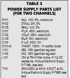
TABLE 3 POWER SUPPLY PARTS LIST (FOR TWO CHANNELS)
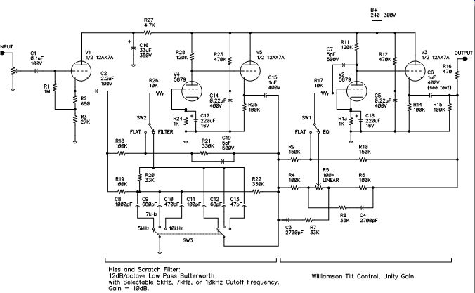
FIGURE 3: Complete line amplifier, incorporating a tilt control and a hiss and scratch filter with selectable cutoff frequencies.
This circuit provides a non-inverting gain of 10dB.
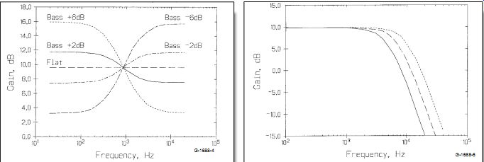
FIGURE 4: Measured frequency response of the tilt control in Fig. 3
for various settings of the potentiometer R5.
FIGURE 5: Measured frequency response of the hiss filter in Fig. 3 for each of its three cutoff frequencies (5kHz, 7kHz, and 10kHz).
POWER SUPPLY
A suitable power supply for either circuit is shown in Fig. 7. Table 3 is the parts list. It uses a 250-0-250V at 40mA, 6.3V CT at 2A power transformer, which I purchased as surplus from Antique Electronic Supply. I've occasionally seen such small transformers available as surplus from various dealers, so call around before you buy a new one. The filter choke L101 can be anything that will handle the 30mA load current in the range of 5-20H. The capacitor across the voltage regulator tubes (C104) must be limited to 0.1µF to prevent possible oscillation. [5] If your power supply is far from your audio circuitry, you can place C104 on the same board as the audio circuits instead of in the supply. This more effectively by passes the power supply at the audio circuitry, where it is important. I recommend a DC heater supply for lowest hum, but this is not absolutely necessary if you just choose to build a quick prototype and "have a listen," as I did. For the more ambitious, a suitable 6.3V DC heater sup ply was described in one of my earlier articles.
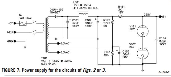
FIGURE 7: Power supply for the circuits of Figs. 2 or 3.
I hope that some audioXpress readers will build this tilt control. If you do, let me know how your project turns out and what you think of its sound.
Also see: