IMPROVING A CLASSIC
"The Future of Vacuum Tubes in Audio, Part 1" (GA 3/00, p. 20) refers to the highly popular Dynaco Stereo 70 power amplifier. Considering its simplicity, it is a fine unit. However, a few simple changes may improve it significantly.
First, the 82pF capacitor in the 7199 pentode plate circuit causes the open loop gain to roll (-3dB) at about 7 to 8kHz.
If high-frequency stability does not suffer, reducing this capacitor to 27pF or 33pF, moving the -3dB point above the audible range, may give clearer highs. You may also need to change the 390pF capacitor between the lower output tube screen grid and the input tube cathode circuit for best high-frequency transient response.
Second, it would be a good idea to provide for measuring and balancing the individual output tube cathode currents. This is important in any amplifier that uses fixed bias. Individual 27 ohm cathode resistors, with a removable jumper to tie the cathodes back together during normal listening use-plus a balance control net work where the 270k grid resistors connect to the bias supply-would do the trick.
One concern I have about the Stereo 70 is the single GZ34/5AR4 rectifier tube, which has a load current rating of 250mA, used to power two pairs of EL34/6CA7s.
Each pair draws 100-120mA idling and 170-180mA at full output, and each 7199 draws 4-5mA. Adding this up and doubling for two channels, the 5AR4 is running near full-rated load current at idle and would be overloaded if the amplifier is being run full blast.
If the power transformer high-voltage winding is rated to handle the full output current, silicon rectifiers with a delayed soft start B+ turn-on would be more reliable. Commercial-duty sound amplifiers using four 6CA7s generally had two 5U4GBs in parallel.
One commendable feature of the Dyna Stereo 70/Mark IV is the absence of an electrolytic bypass capacitor across the 620 ohm 7199 pentode cathode bias resistor.
Michael Kiley; Crestwood, Ill.
TUBE IDENTITY
I have constructed the dynamic head phone amp described in the premier issue of Glass Audio (1988), which has all the clarity that the authors described. A friend of mine auditioned the amp with Sara McLachlan's Surfacing CD. His response was, "I have never heard a cello up close before!" The design calls for a PCL805, which is identical to the ECL805 except the heater voltage is 18. I could find only four PCL805s and I purchased many PCL85s. I could hear no difference between them.
According to the RCA tube manual (RC30), the PCL85 does not exceed any ratings in this circuit. The RCA tube manual does not list the PCL805. I have used the PCL85s for a year now without any difficulty, but I would like to know what the differences are between the PCL805 and PCL85.
Jim Dungan; Port Neches, Tex.
Rickard Berglund responds:
The Philips tube manual states that the PCL85 is identical to the PCL805.
PERFORMANCE MEASURE
I ordered a couple of back issues of GA to review some amplifier designs, and also added a new subscription. The articles were great except for one critical area. They didn't have much in the way of performance testing. Many of these amplifiers may cost $2500 or more to build a pair (monoblocks), not to mention the time involved. To go through that expense and time of building them without really knowing what the outcome will be seems pretty risky for anyone but the most wealthy and those with the most free time.
May I suggest that your authors include a minimum set of specifications such as: frequency response at 1W and full power; distortion at 1W and full power at, say, 20Hz, 1kHz, and 20kHz; output impedance; and power consumption at idle and full power. I am sure you have more ideas about what could be included.
Considering the time it takes the author to build the amplifiers, the time it would take to measure its performance would be minuscule. I think this would not only be helpful to your readers, but also enhance the quality and credibility of your publication.
Michael Adams; Pacific Palisades, Calif.
SURROUND REPAIR
I own four JBL136A 15” woofers purchased in the mid-1970s. About 12 years ago the surrounds turned to powder. I had them re-coned at considerable expense. I was told at that time that the material that JBL used was susceptible to age, humidity, smog, ozone layer depletion, and so forth. Sure enough, it has happened again. Is this repair a procedure that I can do at home, or should I leave it to a professional ? Does anyone make a surround that has a longer life ?
Clif Penick; Northport, Ala.
Contact Image Communications at Dave_Armon.woodsind.com for companies who sell surround repair kits for a wide variety of drivers.
-Ed.
MONARCHY UPGRADE
I just finished reading Gary Galo's article on upgrading the Monarchy DAC (AE 2/99) and had a couple of comments.
The first is that while this mod may work for the parts specified, this does not mean that you can apply it universally.
The Analog Devices (ADI) D/A converter chip AD-1860 was mentioned in the article. There should be a warning. The AD1860 includes an uncommitted op amp designed to be used as an I/V converter. It is not good practice to connect the output of op amps together. If you are going to do this mod with the ADI parts, you should not parallel pins 9, 10, and 11 to the existing IC. Instead, bend them so they are parallel to the body of the IC. Then jumper the opamp output (pin 9) to the inverting input (pin 11). This completes the feedback loop around the op amp and basically takes it out of the picture. If you don't make this connection, the op amp will be running open circuit and could inject noise into the system.
If you were to just hook up the second IC, you may not see any problems. After all, the outputs of the two op amps should be very close to each other and, therefore, shouldn't really be fighting each other.
But for top-end performance, why allow the potential for problems? The second issue is with the trim: specifically, the trim adjusting out of the differential nonlinearity of the MSB. By paralleling the ICs, you limit how close you can adjust out this error. You should always check the adjustment. Just be cause it was set for one D/A chip does not mean that it will be correct for two.
The differences, however, should be minimal. You may need to revisit these adjustments from time to time because of changes due to mechanical vibration, heat, and the like changing the pot set ting. Again, the differences will be minor, but real.
Note that the PCM63 also includes this adjustment. It just isn't included in most designs. Check Fig. 5 of the PCM63 data sheet.
Hank Zumbahlen; Boulder Creek, Calif.
Gary Galo responds:
Hank's points are well-taken, and should be heeded by those who try this modification. Both Monarchy and I ignored the internal I/V converter, since it is not used in the 18B. When Bob Adams of Analog Devices replied to my inquiry regarding the paralleling of the AD1860 DACs, he did not mention these caveats. In his defense, he may have assumed that I was al ready aware of them, and perhaps I should have been.
Regarding the trim, I agree that it is best to check the trim if test equipment is available, and I pointed this out in the article. In my sample of the Monarchy Model 18B, there was no change in linearity when the second DAC chips were paralleled.
But, this may not hold true for every sample.
Burr-Brown does include a provision for external trimming of the PCM63, but its implementation is relatively complex, requiring two external fixed resistors, two trimpots, and two capacitors. As the PCM63 data sheet notes, "Great care should be taken, however, as improper adjustment will easily result in degraded performance." The performance of the PCM63 is so good without external trimming that most manufacturers who use this chip seem to have concluded that the trim procedure is not worth the added expense. Unless the trimming is implemented and adjusted with the greatest of care, performance will actually be worse.
TIME DELAY
I am considering building a pair of the 100W triode amps featured in GA 3/00. Are there any corrections to the schematics as printed? Would the soft-start circuit using the 6X4 ("Glass Shards," GA 3/00, p. 70) be appropriate for the amp ?
Charles Gutzman; Petersburg, Ill. ; Joseph Norwood
Still responds:
Good luck on your 100W project, which is a big one but should prove to be a lot of fun and will certainly give hours of great listening pleasure.
Per changes: Capacitors C5 and C6 shown on the parts list as 0.33µF are correct. The schematic diagram (0.15µF) is in correct. The 0.33µF value improves the 100Hz square wave. (Be sure to use Orange Caps.) Capacitors C6 and C7 on the power supply schematic should be 47nF, while 0.047µF on the parts list is correct. "Available from Antique Electronic Supply" should appear between S1 and R3 on the parts list. The soft-start circuit in the same issue is a novel circuit but would not be able to "handle" the current of the 6-6550s. I recommend a conventional relay with a time-delay circuit. A time-delay device manufactured by CEBEK is available from MCM Electronics (1-800-543-4339), fully assembled, for $19.95, PN28-5100. The time delay is adjustable from 1-180 seconds and has relay contacts rated at 5A. An external 12V DC, 50mA power supply is required to power and activate the timer, which is de activated when power is removed. You may purchase the power supply separately or build the one in my article for about $9; all parts are from Radio Shack. The only modification to my power supply is that you must use a 12V regulator (7812) in stead of the 9V regulator (7809).
I put my "head" and soldering iron to work and came up with a simple, inexpensive time-delay relay (Fig. 1). Table 1 is the parts list. You must be careful when using MOSFETs; first mount all the components on the PC board, then mount the IFR510. Solder the source, then drain and finally gate to the appropriate location. Make sure all capacitors are discharged prior to mounting the IFR510.
Note: When you switch on the IFR510 (after 20 seconds), expect +3V DC at the junction of C3 and R2 and also 0.1V DC at the drain of IFR510.
The cost differential between my unit and the purchased unit is the cost of the 12V DC 50mA supply required to "energize" the commercial unit. The CEBEK unit is certainly more sophisticated than my simple design. I leave it up to you as to which unit you prefer. Personally, I would go with the commercial unit.
TABLE 1
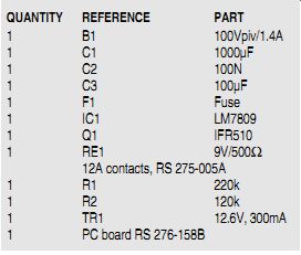
MATERIALS QUANTITY REFERENCE PART 1
B1 100Vpiv/1.4A 1 C1 1000µF 1 C2 100N 1 C3 100µF 1 F1 Fuse 1 IC1 LM7809 1 Q1 IFR510 1 RE1 9V/500 ?
12A contacts, RS 275-005A 1 R1 220k 1 R2 120k 1 TR1 12.6V, 300mA 1 PC board RS 276-158B
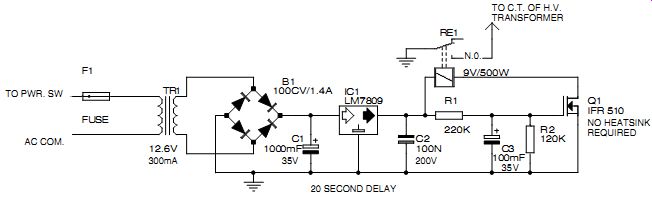
FIGURE 1: A simple time-delay relay, total cost is $18.50, and all parts
are available from Radio Shack.
I can understand your concern with "cathode stripping," since many other readers of GA have requested information on a time-delay circuit. I hope this clarifies the issue and makes everyone aware that the "bare-bones" cost of a time-delay device is $20.
Again, good luck on your project. I suggest this fall or the winter would be an appropriate time for such a massive project.
The amplifier has a great sound, is very stable, and runs quite "cool" (with the aid of the 65 CFM blower fan). The excellent 10kHz square wave of the amplifier is attributed to the low impedance, high-current operation of the 6550s and the excel lent design of the Hammond transformers-and, of course, the triode configurations.
TUBE & GROUND DATA
In GA 2/00, you printed a letter from John Badalamenti inquiring about amplifiers using 807 output tubes (p. 67). Eric Barbour's reply indicated that a pair of 807s could not reliably be driven to 100W. I am submitting a schematic for a Bogen HO-125 amplifier, made around 1950, which used a pair of 807s to obtain 125W (Fig. 2). This unit ran the 807s at 840V, and used parallel 6SN7s as drivers.
I do not know the distortion ratings. While this was a commercial amplifier, there was not much distinction between hi-fi and commercial amplifiers in 1950.
From my experience, 807s are very rugged tubes. While it is true that they were rated at 600 plate volts, this was very conservative. Originally, 807s were used as transmitting tubes. Later, they appeared in receiving tube manuals with specifications for use as Class AB-1 amplifiers. Apparently, they can be used at higher plate voltages and dissipations for audio applications. New and used 807s can easily be found at hamfests.
Also, Mike Gustafson's power supply schematic in the same issue (p. 32) shows what I believe to be a very dangerous error. The indicator lamp is connected from the hot side of the AC line to ground.
The lamp will work, but only if the unit is plugged into a grounded three-wire outlet.
If plugged into an ungrounded or two-wire outlet, 110V AC will appear on the chassis.
The ground wire should never be used as a current-carrying conductor. Its purpose is to carry only fault current, as in the case of an accidental hot wire to chassis short.
If wired as shown, you could receive a nasty shock (through the indicator lamp) if the unit is not grounded and you touch it while you are grounded. If the lamp has high enough wattage, the shock could be fatal. The lamp should be connected across the transformer primary.
As a wise old electrician once told me, "It's better to have a ground rather than to BE one."
Al Forbes; Gastonia, N.C.
PVC PIPE
I have been actively involved in audio at the home level for 40+ years, although I was unfamiliar with your publication until I read the SB 6/00 issue. My interests are as varied-both wide and narrow in scope-as SB appears to be. I especially enjoyed your piece regarding Yoshio Satake and his "museum" ("Showcase," p. 50).
This indicates that your magazine is capable of an element missing in the other "rags": namely, humor. So many audiophiles and wannabes take themselves way too seriously...even Lisa Astor in Stereophile, who, with tongue in cheek, is rather the Martha Stewart of the genre.
Does anyone fool around with HDPE sewer pipe, available in quite a few diameters, @ $1,200 for a 40' section of 8”, for instance. This, a pretty inert material, and hard to work with in some ways, offers many advantages and opportunities for tweakers. For example, a pair of 6'× 8” sections sit on my listening room floor.
They are quite tunable by way of a piece of plywood or potted plant on top, and varying amounts of glass, foam, or crumpled paper inside. It is only available, as far as I know, in basic black, but I fool 'em and cover with a sock of sky-blue silk.
John Thomas; Nome, Alaska
See Scott Wolf's "A Pipe and Ribbon Odyssey," in SB 3/91, pp. 28-30.
-Eds.
ELECTRONIC SPEED CONTROL UPDATE
Since my article "An Electronic Speed Control" (TAA 1/86) was reprinted in The LP Is Back!, I have received letters and telephone calls from several readers noting that the ILP power amplifier module and toroidal transformers are no longer available.
Fortunately, I have found substitutes for all of these parts. Plitron Manufacturing (plitron.com; e-mail: sales@plitron.com) has suitable transformers, and they are now a distributor for the Amplimo line of power amplifier modules, which are manufactured in The Netherlands. They can also be contacted at 1-800-PLITRON (1 800-754-8766) or (416) 667-9914, ext. 236 (Voice); or (416) 667-8928 (FAX). Ask for Helen Chen, customer service.
You should change the ILP HY60 power amplifier to an Amplimo A60. Note that Amplimo's model numbers refer to the 4 ohm power rating. This module is rated at 40W into 8 ohm, a bit higher than the 30W HY60. I do not recommend using the Amplimo A30, since it is rated at only 25W into 8 ohm, and probably won't produce sufficient output voltage under load at the secondary of the step-up transformer.
All parts for the A60 power supply are also available from Plitron, which recommends a 037016201, 80VA power transformer, and the DE capacitor/rectifier assembly. Note that these power-supply parts replace the old ILP PSU-410 supply, which included a 4A027 power trans former and the PCB-410 circuit board with rectifier diodes and filter capacitors. Amplimo also recommends that the LRZ output muting relay be used with their power amp modules. The muting relay may be optional in this application, but it is so in expensive that I recommend using it.
A schematic showing the implementation of the muting relay is available on the Plitron website in an applications note for the amplifier modules. You may also ask for a copy of this when you place your order. The step-up transformer was originally an ILP 1A010, a 30VA unit with dual 6V secondary windings, which are used in series to form a 12V primary in this application. The replacement is the Plitron 017010201.
The XR2206 function generator chip is still available from Jameco Electronics (Jameco 34972; www.jameco.com). The correct Bourns number for P5, the 10-turn 20k pot, is 3541H-1-203 ( Newark 12F5004; newark.com). The Bourns H-491-3 counting dial is also available ( Newark 12F9669). Newark notes that this counting dial is available only in the United States. Outside the US, try Bourns H-492-3 ( Newark #12F9670). This is the same part, but with a break included (so the pot can be locked into one position).
Gary Galo; Potsdam, N.Y.
IT PAYS TO ADVERTISE
I really enjoy reading the editorials in GA. They're always insightful and informative. The one in GA 2/99 was right on the mark, stating that parts suppliers were not advertising enough. I agree. However, I would go further, claiming that tubed equipment manufacturers also do not advertise enough.
It seems as though every day when I open my morning paper I see pages full of hi-tech (imported) audio gear that sounds boring and looks cheap and ugly. I have yet to see even one piece of audio equipment that employs tubes.
If import audio is the norm, why not include Chinese tube amps, such as those appearing in the World Tube Directory?
Could it be that the big shots who own the audio store chains fear that consumer confidence in the widely available hi-tech audio gear just might drop when audio enthusiasts see this hi-tech trash for what it really is ? Would including tubed gear, in short, be "technologically incorrect" ? The tube-equipment manufacturers should catch the wave and really go public with their marvelous innovations. Not doing this is comparable to Mike Tyson fearing a shoe salesman. If the tubed equipment manufacturers seek more audiophiles to road-test their glass, they must first let them know that it even exists. Once they show the mainstream audiophiles what they have to offer, they will surely reap their long-awaited re wards and be the giants they were some 30 years ago.
Neal A. Haight; Castro Valley, Calif.
RECTIFIED TUBES
I doubt that it is wise to use a 6×4 rectifier as shown in "Rectifier Tubes as Soft-Start Controls" (GA 3/00, p. 70). As mentioned in the RCA manual, the heater needs 6.3V-0.6A, which is two times the current mentioned. The maximum positive cathode to heater voltage is 450V, so even at a positive supply of 400V there is no risk of a breakdown. For a higher volt age of, say, +460V you can connect all filaments to, say, +60V.
As the high voltage builds up slowly during warm-up, there is no risk of an overvoltage when switching on the amp.
But, in this configuration, capacitor C1 will immediately charge up to a high negative voltage. This greatly surpasses the specified maximum negative cathode to heater voltage of 100V and will destroy the tube and maybe more.
A.J. van Doorn; Amersfoort, The Netherlands
WORD USE
I am the electronics technician at the COSI Museum of Science and Industry at Toledo, Ohio. Last week, I was discussing with my supervisor and a friend an exhibit designed to demonstrate that W = EI. My friend, a network engineer, wished to set up a parallel exhibit in fluidics "to show that voltage is like the diameter of the pipe, and current is like the height." [Funny how computers have al most nothing to do with electronics!] Of course, I explained that the pipe diameter was analogous to resistance, but when I got to height, or "head," I had a problem. I explained that voltage lacks the parameter "area," and that the analogy with pressure was therefore inexact, but close enough for most people. That was an evasion.
First of all, head is force/unit area. Since it is normalized to unit area, it is essentially a unit of force. If I had used the correct terminology, I would have spoken in terms of electromotive force, and the conflict would have vanished, but people understand voltage more readily than EMF. Thus, the price for avoiding Mr. Dell's "pressure of a voltage difference" is more confusion (SB Mailbox, "More Words," SB 5/99, p. 44).
I solved the problem in my exhibit by making two parallel statements: "Electric Force × Electric Current = Power," and "Volts × Amperes = Watts," thus separating usage from measurement. This is the case in Europe, I believe, where the symbols V and u are both used for "voltage." They would say, for example, "a 12V power supply which measured 11.93u." Unfortunately, we Americans [well, "Norteameri canos"] are not that far advanced.
As for the differences between voltage and "meterage"--I don't think your distinction holds up. Languages are full of examples of inconsistent patterns of use.
Consider the series: Asians, Canadians, Africans, Germans, French, Finnish, and Japanese. And it doesn't get any better if we substitute "Frenchmen," "Deutch landers," and so on.
We have a mixed bag in electronics. We have voltage, amperage, and wattage, but we also have the 'ances-resistance, susceptible impedance, reactance, and so on. (All of these are French suffixes. Hmmm.) So we actually have two distinct patterns. Another fact I find curious is that while "voltage" is a simple force often assigned to quality of a rate, "amperage" is a rate dressed up as a simple quantity. Go figure! Actually, charge is the first quality in electronics (and is singularly free of suffixes, or even a clear plural form). All other qualities are derived from charge and cannot exist without invoking it.
Next come quantity (Coulomb) and difference (voltage); then the ratios start, current, conductance...I absolutely refuse to go into the mechanics of charge! Chemistry ends with the atom, and electricity ends with charge.
Bob McIntyre sideshowbobmac@thesimpsons.com
BUYER BEWARE
I have an assortment of used 12AU7/ T7/X7s and noticed something that took me aback. Every one of my Mullard and Telefunken tubes have a defect in the heaters. When inserted into circuits with a 6.3V AC heater source, the heaters go table-lamp-bright when I switch on the equipment. The surge in brightness lasts for a second or two. I didn't pay much attention to it until a couple burned out.
The strange thing is that this occurs in all tubes made in either Great Britain, Germany, Holland, or France. For example, if I pick out two Sylvania 12AX7s, one made in Europe and the other made in the U.S., the European tube will act this way while the U.S.-made tube behaves normally. In DC heater-sourced circuits, the Euro tubes work well, performing up to their reputation.
If you're ready to re-tube a vintage integrated amplifier, put the Euros in the phono preamp stage, and U.S. tubes in AF amp and phase-inverter stages. Of course, certain amps have an AC heater source throughout the amp, so it may be best to refer to the schematic, or consult an expert, to determine which locations are AC or DC heater-sourced. Back when Euro tubes cost four or five dollars, it was nothing to really lose sleep over, but today they go for big bucks-a major supplier is selling Mullard 12AX7s for $60 a piece. I believe the defect takes place when the tubes become older and have been used for quite a few hours.
Japanese 12AX7s are as reliable, heater-wise, as U.S.-made NOS tubes. I hope Chinese tubes are at least equally as good as the Japanese tubes.
One brand of tubes I always see advertised in Glass Audio are J-J tubes. As I understand, these tubes are made in Slovakia. They look rather nice in the advertisement photo.
Whenever Vacuum Tube Valley compares tube types in their "shootout" articles, J-J tubes aren't ever mentioned. I have tried to obtain information on several occasions, but J-J hasn't responded so far. I would like to find out how they perform, which is difficult.
In conclusion, I'd say that U.S.-made tubes are a real bargain and should be the first choice for tube buyers.
Neal A. Haight; Castro Valley, Calif.
DRIVER CIRCUIT FOR 6AS7 AMP
Thank you for the recent articles1-3 on low-mu triode push-pull (pp) power amplifiers. I found them so interesting that I have built one myself. however, the driver and input circuits are different, and I believe some readers who have embarked on this project may find the following information useful. Low-mu power triodes usually require very large drive signals, probably in the order of 200V peak-to-peak. This may be two or three times higher than that used in a typical pentode or tetrode pp amplifier. To achieve this requirement, Stewart [1,2] uses a form of positive feedback, while Cottrell uses an interstage trans former. I prefer not to use positive feedback*, and I do not have an interstage transformer. Therefore, I set out to design an input/ driver circuit that can provide 200V peak-to-peak with "reasonable" distortions and gain.
The required devices and components must be readily available and cheap. The result is shown in Fig. 3. The complete de sign consists of two cathode-coupled stages, with the second directly coupled to the first. The first stage utilizes the most popular triode on earth, and the second stage uses the 5687, which is popular in many Asian designs. Simulations showed that the 5687 is more linear than the 12AU7 or the 6SN7 under this operating condition.
The output stage is not shown because it is very similar to those described in references 1-4, except that I use paralleled 6AS7s or a pair of 6C33C-Bs. Measurements for this circuit are shown in Table 2 with some additional comments. This has been successfully used to drive either 8 × ½ 6AS7s or 2 × 6C33C-Bs in push-pull mode. I have not implemented the drivers of references 1 and 3 and cannot make direct comparisons. I would like to hear comments from others.
Using 6C33C-Bs instead of 6AS7s may be another alternative that readers can try and comment on. I tend to prefer the 6C33C-Bs. Reference 4 gives a good description on the use of these very powerful Russian triodes.
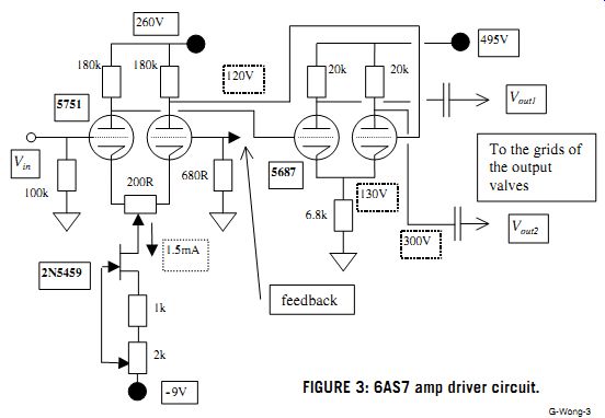
FIGURE 3: 6AS7 amp driver circuit.

TABLE 2 OPEN-LOOP CHARACTERISTICS
• Gain ˜ 300 (50dB)
• Vout
˜ 70V RMS @ around 1% THD (50Hz to 15kHz)
• Vout
˜ 80V RMS before clipping
• Frequency response ˜ 40kHz, -3dB NOTE:
• Voltages indicated are not exact and may vary slightly.
• The main adjustment is to vary the two VRs of the first stage such that the two output voltages are identical (or as close as possible) and as symmetrical as possible-this can be easily done using a two-trace CRO.
• The 1k resistor is used to measure the bias current.
• Using well-matched input valves may eliminate the 200R VR and will extend the frequency response and increase the overall gain.
• 12AX7 may replace 5751 in the front stage.
• The overall open-loop gain of the complete amp is around 36dB (this is dependent on the output transformer used) and is ready to take a negative feedback of up to around 12dB. I believe 6-10dB will suffice.
REFERENCES
1. J. Stewart, "A Different Triode Power Amp," GA 2/99, p. 50.
2. J. Stewart, "An Updated Triode Power Amp," GA 4/99, p. 46.
3. M. J. Cottrell, "6AS7 Amplifier," GA 6/99, p. 20.
4. D. J. F. David and J. B. Fortias, "Triode Power Amplifier 6C33C-B," GA 2/99, p. 1.
* I believe the proper use of positive feed back will work, but there are other problems in addition to stability that I would like to avoid.
CC Wong Dept. of Communication & Electronic Eng.
RMIT University Melbourne, Australia
John L. Stewart responds:
It is gratifying to know that someone is reading your stuff and then trying something new. As with all designs there are trade offs. My objectives in regard to the "Different Triode Power Amp" were to sidestep some of the more serious problems associated with higher power triode amplifiers.
I intended the design to:
1) Avoid dangerous high-voltage power supplies
2) Use readily available, inexpensive components
3) Eliminate frills such as driver transformers, DC heater sup plies, and so on At this point, I would like to propose another class of amplifier as follows:
CLASS
USA U-understandable S-safe A-affordable
With regard to CC Wong's amplifier, I have the following observations.
The first stage using the 5751 (or 12AX7) may have problems when feedback is connected to close the loop. Using a semiconductor as a current source is a good idea. However, in the proposed circuit there is not enough common mode tolerance*. A 9V battery is being used here; 4.5V are used in passing through the biasing resistors. That leaves only 4.5V to operate the 2N5459 and provide current to the 5751 differential pair.
Using my development amplifier, I connected feedback to give an overall gain of 6 from the input to the 8 ohm output terminals. I measured 1.62V RMS at the cathodes of the first differential pair while the amplifier was delivering 20W. That would be 4.58V peak-to-peak. If the 2N5459 bias circuit were used, there would be lots of distortion. I would use another 9V battery to get 18V and a margin of safety. The development amplifier avoids this problem by using a -150V supply.
The 5687 is a very good twin triode and can easily deliver large output as a driver to a power stage. The 7119 is another twin triode that could serve equally well.
In my library I have data covering the 5687 but no curves.
In order to make a comparison with the 6SN7GTB I had used in the development amplifier, I needed, in particular, a plot of the zero bias curve to overlay this onto the 6SN7GTB curves and from that determine how much more voltage swing to expect from the 5687.
To get that information I hay-wired a simple circuit with suitable load resistors (Fig. 4). Power was supplied by a variable regulated power supply set to 365V. The load resistors measured 21.6k. These conditions are a close match to that of CC Wong's circuit. I tried four 5687s. Voltage measured at the test points for the eight triodes was from 48 to 51. If anyone tries this, the load resistors should be 10W.
Using the 3/2's power law, I plotted the zero bias line for the 5687 onto the plate characteristics for the 6SN7GTB family (Fig. 5). You may notice the graph is labeled 6J5. The 6SN7 family is actually two 6J5s in the same bottle. Scaling on this graph was more convenient than that given for the 6SN7 family.
The 5687 can turn on about 63V farther than the 6SN7 with a 20k loadline. Needless to say, I can't go any farther the other way. If you assume cutoff to be at 350V, the 5687 can swing 300V. The 6SN7 will be good for 235V. The 5687 gives a 28% improvement. These numbers are rather ideal since they assume a DC load line. In practice, both will be reduced by rotation clockwise of the loadline under AC load conditions.
Both swings are extended 100% in the development amplifier by bootstrapping, which acts like a tracking power supply that makes available extra voltage when required. For those who are concerned that it is positive feedback, it measured 1.38dB in the development amplifier.
Total DC across the driver stage in CC Wong's amplifier is 495V. He will need an extra power supply either separate or piggybacked to the 260V supply. Either way would require an extra HV winding on the power transformer. I managed to avoid that complication by using a negative supply for part of the power requirements. It uses the same winding on the transformer as the positive supply. He may also need an extra heater supply to avoid heater cathode insulation problems.
*Common mode tolerance-ability of the amplifier to respond when both inputs are driven in the same direction. This is limited by the supply voltages.
Matthew Cottrell responds:
CC Wong raises some interesting points here, to which I would add a few comments, as follows:
1. Yes, low-µ power triodes require large drive signal amplitudes. In my example, a near-copy of McProud's amplifier, the interstage transformer provides about 190V peak-to-peak grid voltage to the 6AS7 output tubes. When I first pro posed this article to Ed Dell, his initial comment was along the lines of "...I will be interested to see how you drive the somewhat difficult 6AS7 output stage...." As I remarked in my article, I only built this monstrosity because I had happened upon some interstage transformers. I probably wouldn't build it again.
2. While quality interstage transformers are fine, classic solutions to high drive requirements, they are very difficult to source nowadays, so using an active solution is a really good idea. In my opinion, the differential amplifier-and other cathode-coupled variants-shown by Wong is perhaps the best alternative.
The differential amplifier is, I believe, sadly under-utilized in audio in general. It can serve as a gain stage with really good common-mode (and power supply) rejection, as a phase splitter, as a balanced amplifier, as a null indicator, and so forth. It has good gain and impedance characteristics, and can be improved even further by the addition of a constant-current source as the cathode resistor, as Wong does in his first stage.
In addition, one of its best features is that it provides a second input at ground potential for the application of feed back, as Wong shows. This eliminates one more capacitor, as compared to applying feedback to the cathode of a single-ended input stage, as is frequently done.
3. The 5687 appears to be an acceptable dual triode for this application, although I am unfamiliar with it in practice. I still prefer the 6SL7 and 6SN7 for almost all such applications (I just don't like miniature tubes). If Wong has proven to himself that the 5687 is a more linear device, then I stand corrected.
Again, though, regardless of the tubes employed, I think Wong's circuit is a marvelous way of developing the high drive voltage required for the low-µ output stage, be it 6AS7s, 6C33C-Bs, or other choices. I will probably breadboard his circuit to try it myself!
4. In general, I agree with Wong that the use of positive ...
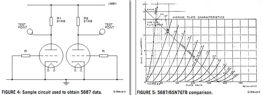
FIGURE 4: Sample circuit used to obtain 5687 data. FIGURE 5: 5687/6SN7GTB
comparison.
... feedback is difficult to implement at best-I have built far too many [inadvertent] oscillators in my time, and don't care to tempt fate by deliberately introducing positive feedback into an otherwise stable circuit.
CIRCLOTRON
My notes in GA 4/00 on selection of the load impedance for the 6AS7/6080 bootstrapped amplifier when compared to Monny Nisel's amplifier are incomplete (Letters, p. 62). I somehow managed to overlook that his amplifier uses the Circlotron circuit (Fig. 6).
The Circlotron has an important advantage when compared to an ordinary push pull amplifier. The output tubes are driving the load in parallel rather than series as they do in common push-pull. That means the output transformer required to properly match to the load needs to be just one-quarter of the impedance of that used in the common push-pull configuration.
His amplifier using a 1k-ohm load impedance translates to a 4k load impedance if it were in the common push-pull hookup.
The advantage conferred here is that it is easier to build a good output transformer as you lower the impedance.
Since nothing comes free, there is as well an important disadvantage. The Circlotron needs two identical high-voltage supplies. Also, the amplifier output must drive the stray capacitance of the power supply. Luckily, output is taken from the cathodes, which are a low impedance drive point. With enough power triodes, you can drive a loudspeaker directly with out an output transformer.
Power transformers with the required two HV windings and output transformers with matching impedances of one-quarter that commonly found have never been easily available as standard catalog items. As a result, few amateurs or experimenters have tried this kind of circuit. That includes yours truly. Perhaps next year ?
John L. Stewart; King City, ON Canada
------------
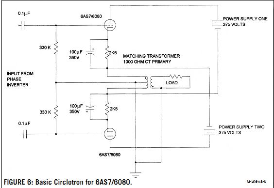
FIGURE 6: Basic Circlotron for 6AS7/6080.
HELP WANTED
I have four ribbon horn tweeters from Decca, or more precisely, the "Decca London Horns." Where can I find replacement ribbons? Money is not an issue.
Harry Timmerman HTI@joco.nl
Several years ago, we published an article by a man whose hobby is rebuilding microphones-including ribbons. He had a method of finding industrial-type film, aluminum sputtered, which he formed in a jig and installed in ribbon mikes. I don't know whether his current address is valid or whether he can help, but you might try him and learn to make replacements yourself.
His address is:
David Royer, 628 W. Amerige Ave., Fullerton, CA 92632.
-E.T.D.
I have acquired a valve TV and need a schematic. I cannot find anyone who can help. The set is an HMV Boston Model PP AE.
Peter Laurence laurence@intercoast.com.au
I have a tube preamp made by GSI musical electronics model 5tp. In my search, I have been informed that the company no longer exists. Where can I locate a schematic or any available information on this unit? Scott Cromwell kronell@wans.net Where can I find the Quad Cap for the Dynaco MkIII mono amp ? Is there an acceptable replacement? I'm also looking for a diagram on how to add a second bias adjustment to individually adjust the tubes.
D. Sherfy thx1326@swbell.net
I am looking for someone-preferably in California-who can modify my Dynaco ST-70 per Norman L. Koren's article in GA 1/92 ("Modifying the Dynaco ST-10 with Triode Mode").
Alberto Sarmiento; 2837 Galena Ave.
Simi Valley, CA 93065
I'm searching for a cabinet builder for a vintage pair of Tannoy 12” dual concentrics. Might you be able to recommend someone?
D. Milch dmilch@bellatlantic.net
Which of the various types of phase splitter circuits is the one also known as a "Loyez" phase splitter? This seems to be a colloquial term for one of the types that uses a double, or two single, triodes. If it is not a commonly known type, then I would be most interested to see a basic sketch of its circuit, as may other readers.
Chris Logan 1/ 14 Brodie Street Paddington N.S.W. 2021 Australia
I am looking for PSpice models on valves, especially small-signal types such as ECC81/82/88 which I can import into Microsim 8 in order to simulate in a hybrid design of my own. I have managed to produce the symbol and the template within the software, but now need the subcircuit information to go with it. I have found several relevant references to previous articles in GA on the Web, so I know there must be something out there.
Paul Bailey
Paul.Bailey@theseed.net
Readers with information on these topics are encouraged to respond directly to the letter writers at the addresses provided.
-Eds.
Also see:
GLASS SHARD: Taming High Line Voltage