Here's the second in a series of quick-and-easy projects to hone your
speaker-building skills, which you can someday apply to your dream
undertaking.
By LM
I had just purchased (for about $60 from an MCM sale catalog) a 70W subwoofer amplifier with which to experiment. I had planned to use it with a dual-voice-coil (DVC) 8 ohm unit, but after reading the fine print that came in the box--"4 ohm minimum load; no warranty if you blow it up," or words to that effect--I knew it wasn't going to work.
The 8” DVC woofer was 4 ohm on each coil, and the two in parallel meant 2 ohm. I tried the coils in series, but the amp did not seem to drive the speaker to realistic levels. It just didn't have the needed power.
Then, as I was about to send the amp back, I remembered the two $10 6” Martin W-678 woofers I had on hand. They had been in another pair of cabinets, a two-way design, and I had replaced them with upgrades to newer poly-fiber units. So now the orphans were just collecting dust, and they were 8 ohm each!
I decided to give them another life.
A SECOND LIFE
Most 6” drivers work well in a 0.5ft^3 box. I intended to put both speakers and the amp in the same box, which meant 2 × 0.5ft^3, for a total box size of 1ft^3. I didn't worry about the volume lost to the amp or the speakers, and since the box was small, it would need no braces.
Speaker designers like to use terms like "golden mean," "golden section" and other esoteric names, but they're just box dimension ratios, such as 0.6:1:1.6, or 0.79:1:1.26. The objective of using such ratios is to build an enclosure with dimensions that do not match up with each other in any way that would cause a reinforcement, which simply means an adding of the sounds inside the box.
Achieving non-resonance is the aim.
For example, a box 12”× 24”× 48” would not be good, since the dimensions, being exact multiples of one another, would produce that reinforcement of particular frequencies just mentioned as being un desirable. Following is a series of rules of thumb for determining desirable dimensions.
First, 1ft^3 = 12”× 12”× 12”= 1,728in^3.
You can use this for a box of any volume--2ft^3, 3.5ft^3, or whatever. In your calculator, enter the volume in cubic feet, multiply by 1728, and you get the volume in cubic inches.
If, for example, you have a 3.5ft^3 box, multi ply 3.5 by 1,728, obtaining 6,048in^3. Now find the cube root of 6,048, which is a bit larger than 18”.
That's the middle inner dimension of the box. Then, using the ratios 0.6:1:1.6, 18”× 1.6 = 30” (the long dimension), and 18”× 0.6 = 11” (the short dimension). So your 3.5ft^3 box would have inner dimensions of 11”× 18”× 30”.
Now, using the alternative second ratio, 0.79:1:1.26, the inside dimensions of a 1ft^3 box are approximately 9.5”× 12”× 15”. To get the outside dimensions, add the thickness of the material you intend to use, which results in 11”× 13.5”× 16.5” with ¾” material.
[For another discussion on this subject, see Louis McClure's article, "Determining Optimum Box Dimensions," SB 2/00, p. 42. -Ed.]
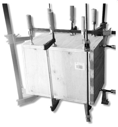
PHOTO 1: The box glued and thoroughly clamped.
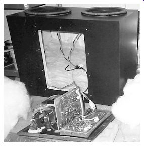
PHOTO 2: Twin subwoofer, with amplifier module in foreground.
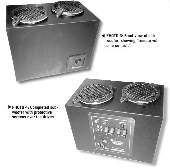
PHOTO 3: Front view of sub woofer, showing "remote volume control."
PHOTO 4: Completed sub woofer with protective screens over the drives.
BUILDING THE BOX
Looking around, I found some old ply wood, and quickly measured it. Not quite enough, but with the amount on hand, the boxes became 10”× 12”× 16” on the out side. This is only about 0.75ft^3 on the in side, but being a tad smaller may not be a bad thing, since it might help with the power handling. Commercial speakers are often mounted in smaller than optimum boxes. Besides the economics (less wood, weight, and shipping costs), this has the advantage of increased power handling because of the compression of the air.
I glued the box together using small finishing nails to hold things in place and then bar clamps to squeeze the glue out of all the joints at once (Photo 1). I let it set overnight. The next morning, upon removing the clamps, I saw that two ends were slightly oversized through my quick cutting, so, using the router with a trimming bit, I cut them smooth and clean in about five minutes.
Now I had a completely sealed box, and I took it to the bench where the speakers were, and set them on top. It didn't look quite right, so I turned the box around so the long narrow side was on top, and placed the speakers on it again. Yes, the amplifier would look perfect in the center of the largest panel (Photo 2).
Take your square, mark your center lines, measure equal amounts, and pencil in the cutouts. The amp needed an 8.75” by 6.75” opening in what would become the back. The "remote control"-a volume control on a wire-would be mounted on the front in a 2.5”× 3.5625” opening. For the speakers, you need to cut 5” circles into the top, offsetting them diagonally to make a good fit.
APPLYING THE FINISH
First drill your start holes. I used a ³/8” brad-point bit, since it doesn't wobble around while you're getting the bit to bite into the wood. Then use the saber saw.
Go slowly here--no mistakes at this point!
Once all the holes are cut, decide on a finish. Luckily, I had some big scraps of black Formica, and, laying them on the panels, I found there was enough. I cut the pieces about ½” oversized, so they wouldn't need super alignment over the sides.
Working with Formica is very easy--just be sure to allow the adhesive to dry.
Coat the back of the material first and place it in front of a fan or in any drafty spot. Then coat your clean plywood en closure, because the wood soaks up the adhesive, and the laminate does not.
Once completely dry, looking milky and with no wet spots, it's ready to stick together.
First, place two dowels across the tacky plywood panel and carefully position the laminate on them. Then carefully remove the dowels, one at a time, with one hand, while pressing the laminate into position with the other. Once it's in place, use a 3” rubber roller with body-weight pressure to ensure complete contact. When this is done, trim off the excess with the router.
Use a mill file, held at a 45° angle, to break the edges all around. If you don't do this, you can get some nasty cuts as you run your hand over the edges.
Find the depressions where you made the cutouts, drill a big guide hole, and rout out the shapes where you'll mount everything. If you don't wish to laminate, try sanding and spray paint. Use a primer first (it saves a lot of paint), allow it to dry, and then sand and add the finish coat. Sand again if you plan to add a second coat.
MOUNTING THE SPEAKERS
I had originally planned to mount the speakers in a push-pull arrangement, where one faces up, and the other faces down into the box. They are then connected so they both move in the same direction at once. Use a 1.5V battery across each speaker in turn to test them if you are not sure of the polarity. The rationale for push-pull is that most speakers do not move in and out on their suspension in a linear way, but mounting them push-pull tends to cancel this nonlinearity.
However, looking at the old driver's backside was not too appealing, so I mounted them both face up after soldering 10” red and black leads to each. I used foam weather stripping to make an air tight seal. Then I mounted the volume control on the front (Photo 3)--it already had foam seal in place. Plug the connectors together at the amp. Use short, black sheetrock screws, hand-seated, so you don't rip out the MDF. Mark out the amplifier holes and predrill, making sure things are lined up in the center of the cutout.
Then choose some sort of damping material to go inside the box. I prefer using dacron polyester on small sealed boxes, but you can also use fiberglass insulation.
Put in enough so that all the interior is filled, but do not pack it tightly. If you have a small scale, you can weigh the damping, using 0.5 lb per cubic foot as a rule of thumb. For this ¾ ft^3 box, try ³/8 lb or so.
Once you listen to the speakers, you can add or subtract filling, note the differences in the sound, and then make it the way you prefer.
Fish around to find the speaker leads, and match them to the red and black of the amp's output. Strip the wire and use standard wire nuts to connect everything.
Then mount the amp and carefully screw it down to ensure a good seal.
FINAL CONNECTIONS
Now you're ready to connect to your system. You can use either RCA interconnects from your line amplifier, or parallel leads from the speaker outputs of the main stereo amp to the terminals on the sub-amp. I tried both, but the second method seemed to give more signal (volume) to the subwoofer's amp, so that's what I used.
After turning it off, I simply placed the new dual subwoofer on top of my approximately 4ft^3 box (see "Bessel Box Sub woofer," SB 2/99) and made a judgment call on the level settings. I put on a CD and sat back. After a few adjustments, everything was blending right in. The used speakers did not require any break in period, but sounded good right off the bat (Photo 4).
The sound does not go as deep as the bigger unit, but it does fill in smoothly after a few adjustments of the volume control. There's a good, solid response in the 60-160Hz range, and this is where most smaller stand-mounted speakers begin to roll off in the bass, because of their distance from the floor, and usually from the side walls, too.
The little dual woofers worked their magic. They are very easy to live with, and they don't set the house to vibrating like the bigger subs. This dual-woofer/ amp setup might be worth considering if you're an apartment dweller with neighbors who don't appreciate your musical taste. This is not an over-the-top, blow-you out-of-the-room "THX certified" subwoofer; it just plays music.
Also see: