15 WATTS PER CHANNEL FOR LESS THAN $150---Our frugal friend presents a tube amp design for first-time builders. By Bruce Brown, RPh.
This "cute" tube amp delivers ... and at a price that should interest many first-timers.
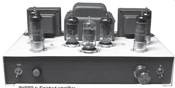
PHOTO 1: Finished amplifier.
I love building stuff! It makes no difference if it is from wood, metal, plastic, or scrap. This is my rel axation therapy. I don't mind spending money for this, but if you have read my previous articles, you know I am also basically thrifty (some would say cheap). The last tube amp I built cost me a small fortune (over $500, with the output transformers costing $150 each) even with scrounging, and I don't believe most hobbyists really care to spend this kind of money routinely.
I decided to embark on a project to see how inexpensively an average hobbyist can build a high-quality tube amp (Photo 1) with ample power to drive most speakers. I set $150 as my goal, which includes everything down to the hardware and the tubes! I will walk you through the project from design to execution and the final listening test.
TRANSFORMERS
The first step is to get the "iron." Transformers can be very expensive, but if you watch eBay you can find some real bargains. Look for complete "off brand" integrated tube amps from the 60s using tubes that are no longer commonly available. These might include 6BM8, 7355, 7027, 7212, and the like Because tubes for many of these aren't easily available, many sellers just want to dump the amps. If you buy a complete chassis, you might even be able to lower your cost further if the chassis includes switches, knobs, and sockets, in addition to the transformers. (This is always a challenge for me, because I prefer to see whether I can fix the unit rather than parting it out.) I found a set of ...
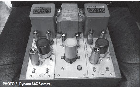
PHOTO 2: Dynaco 6AQ5 amps.
... output transformers and a power transformer from a Harman-Kardon A-100 integrated amp. I contacted the seller to see whether he still had the chassis and he said he threw it out (not much of a scrounger, I guess). I successfully bid on them at $62, including flat rate shipping.
TUBES
Because I had used about one-third of my budget already, I needed to pick a simple circuit and inexpensive tubes. I also wanted to get at least 15W RMS per channel. I checked prices of output tubes-6L6s, EL34s, 6BQ5s, 6550s, or KT88s-and found it was going to be tough to stay within the budget. 6V6s looked pretty good, but they tend to bring about $10 each for good quality.
Sometime back I bought a pair of chassis with Dynaco 410 outputs on each one. These amps used a 7199 driver/phase inverter, and a pair of 6AQ5s as outputs. They were probably from some commercial recording monitor amp.
I bought the chassis primarily for the transformers, but like a lot of stuff that enters my shop, I decided to try to revive them, instead of parting them out.
They were constructed very well, and used oil caps for coupling. I reverse engineered the circuit. They were wired for ultralinear operation. Each required a filament supply and relatively filtered HV DC. I dug up a suitable power transformer, and designed a base and chassis top around them. They turned out pretty well and sounded wonderful, very neutral, and natural (Photo 2).
The 6AQ5, a 7-pin miniature version of the 6V6 octal tube, is pretty cheap. A quick check of online auctions showed that they were selling for about $2-3 each for NOS tubes. I bought ten NOS Westinghouse branded, in sleeves of five, for $18 total with shipping. The only drawback is that these tubes have a m aximum plate voltage rating of 275V (I will discuss how to deal with this later).
There are thousands of schematics for tube amps out there, and I am sure many of you have a favorite. Several of my previous articles centered on using a Pilot 410 circuit. As I have discussed before, you can use a wide variety of transformers and tubes with this circuit and modify values accordingly (audioXpress 12/05). I decided to use the Pilot circuit as the basis for this amp. I needed three dual tri ode tubes for the preamp, driver, and phase inverters (Fig. 1). The goal of low cost moved me to the 12AU7, which is probably the most common dual triode tube in the world, and so is also very economical.
With the exception of Telefunkens, Mullards, and the like, you can buy these tubes NOS for less than $4 each and sometimes snag 20 used ones for $10-15.
I don't believe in spending much money for "black plate," "gray plate," "d getter," "triple mica support," "military," or "clear top" tubes. Except for very specific situations, these are generally a waste of money. (Before you write audioXpress with your outrage, please consider doing randomized double-blinded listening tests and publishing the results). Can you hear differences in tubes? Yes, you can, but how much and will it make a difference in the pleasure you get from the amplifier?
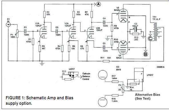
FIGURE 1: Schematic Amp and Bias supply option.
CHASSIS
With the selection of my transformers and tubes, it was time for a suitable chassis. In keeping with my thrifty theme, I dug out a few things I had stashed. A couple of months ago I was in one of my favorite surplus stores (Gateway Electronics, St. Louis) and stumbled across some very nice enclosures that had previously housed a switching system for parallel port printers. These were pretty solid, with a powder coat beige finish.
The sockets, switch, and internal wiring were gone, but the price was $4 each.
I bought all three and put them in my storage area. I took out one of these and arranged the transformers and tube sockets on the top and decided that it would work just fine. Photo 3 shows a silver front panel, which, carefully using a single-edge razor blade, I lifted and cleaned up with a little "goo gone." I started by making some aluminum panels to fill the rear holes, and bolted them using the predrilled chassis holes.
The center one was conveniently filled with a barrier strip, for speaker connections. I decided to add a few dollars to the project by including two sets of input jacks and a front panel selector switch. A power switch, pilot light, and volume control completed the front panel. The transformers had a little light rust, so I painted them with a Rustoleum Textured brown finish. (I thought it would contrast nicely with the beige powder coat.) I also painted the front and back panel portion of the cabinet with the same paint.
Before you try to paint powder coat finishes, you must rough up the surface with some fine sandpaper or Scotch-brite pad. If you don't, the paint will not stick, and will flake off over time.
(This is another reason that powder coat is such a great product. It is not only extremely durable, but dirt, grime, and even paint won't stick to it.) While the paint was drying, I punched and drilled the holes for tube sockets, transformers, and wire grommet holes (Photo 4). When you are using a clamshell-type chassis, it is extremely important to locate components carefully. A small metal machinist ruler is very handy for measuring potential interference between the top and lower chassis parts. Because of the compact nature of this amplifier, this step is essential.
WIRING
Once I mounted the top chassis components, I started the wiring process.
I prefer to begin with filament wiring, twisting the leads together and routing them close to the chassis and as far away from the input grids of the preamp and driver tubes (Photo 5).
Next, I laid out the high voltage section, taking special care to allow easy ac cess to the decoupling resistors between the power supply capacitors (I knew I would need to play with some of the values to get the voltages right for the various tubes). The overall high voltage that feeds the output transformers can't exceed 275V for the plates of the 6AQ5 tubes, so you may need to make some adjustments.
Harman-Kardon (and Fisher) commonly used a single non-center tapped high volt age winding, so a voltage doubler is necessary. If your transformer has a center tap, your power supply can be a little simpler (and cost less).
I proceeded to wiring the output stage and worked forward to the phase inverter and driver sections. My builds progress whenever I have an hour to spare, so I make a copy of the schematic and check off each component as I wire the amp. I also use a marker to label connection points directly on the bottom of the chassis. Typically these include high voltage and feedback connections. This allows me to check voltages quickly on startup and for later fine-tuning.
When starting a build, I collect all the resistors and capacitors and place them in a container on my bench. This helps to keep track of what wiring is done and what needs to be done. When I am out of parts and everything is checked off the schematic, I know I am close to being finished. It is a good idea to take a break after you complete your wiring, and then come back and verify the wiring before you fire up. Photo 6 shows the completed power supply wiring and one channel of the amp wiring.
Then I wired the bottom half of the clamshell, which included all the input, output, and AC wiring. I wanted to be able to wire the two parts together and still be able to open them on the bench ...
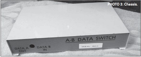
PHOTO 3: Chassis.
... for service, so wire routing becomes an issue. The AC and input wiring are separated as far as they can be. I had been concerned with the length of the shielded cable from the volume control to the preamp tube. I decided that if I had a hum problem I would shorten them, but it turned out there were no issues.
STARTUP
Firing up the completed amp, I was greeted with a howl, which generally means you have the primary and secondary of the output transformers out of phase. A quick switch of the primary windings solved that problem. (One of these days I am going to build the phase-checking device featured in Glass Audio 10/99 by Charles Hansen.) On the second startup, as I neared 100V AC on the primary of the power trans former, I measured about 270V DC at the plates of the output tubes, so I would need to make some adjustment of the high voltage.
The first decoupling resistor in the power supply was a 50 ohm 10W between the voltage doubler and the rest of the power supply. Some experimenting indicated that I was going to need about 500 ohm . I first put a 10W unit in, but it became uncomfortably warm. Digging around, I found a 430 ohm 25W unit that I had scrounged from some military surplus and it worked just fine, becoming a little warm to the touch.
The parts list indicates two 1K 10W resistors, which you need to parallel. Now the measured voltage at the plates at 120V AC on the primary was 262V DC. Measurement of plate voltages on the preamp, driver, and phase inverter tubes was lower than I liked, so I adjusted the decoupling resistor values to get in the ballpark.
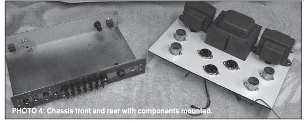
PHOTO 4: Chassis front and rear with components mounted.
---------------
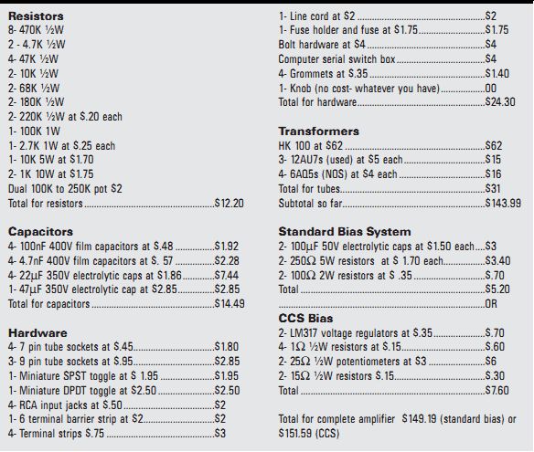
Resistors 8- 470K ½W 2 - 4.7K ½W 4- 47K ½W 2- 10K ½W 2- 68K ½W 2- 180K ½W 2- 220K ½W at $.20 each 1- 100K 1W 1- 2.7K 1W at $.25 each 1- 10K 5W at $1.70 2- 1K 10W at $1.75 Dual 100K to 250K pot $2
Total for resistors ...$12.20
Capacitors
4- 100nF 400V film capacitors at $.48 $1.92 4- 4.7nF 400V film capacitors at $. 57 $2.28 4- 22MF 350V electrolytic caps at $1.86 .$7.44 1- 47MF 350V electrolytic cap at $2.85 ...$2.85
Total for capacitors $14.49
Hardware
4- 7 pin tube sockets at $.45 ...$1.80 3- 9 pin tube sockets at $.95 ...$2.85 1- Miniature SPST toggle at $ 1.95 ..$1.95 1- Miniature DPDT toggle at $2.50 ...$2.50 4- RCA input jacks at $.50 ...$2 1- 6 terminal barrier strip at $2...$2 4- Terminal strips $.75 ..$3 1- Line cord at $2 ..$2 1- Fuse holder and fuse at $1.75 ...$1.75 Bolt hardware at $4 ..$4
Computer serial switch box ..$4 4- Grommets at $.35 .$1.40 1- Knob (no cost- whatever you have) ..00
Total for hardware ..$24.30
Transformers
HK 100 at $62 .$62 3- 12AU7s (used) at $5 each ...$15 4- 6AQ5s (NOS) at $4 each .$16 Total for tubes...$31 Subtotal so far ..$143.99
Standard Bias System 2- 100MF 50V electrolytic caps at $1.50 each $3 2- 2507 5W resistors at $ 1.70 each.$3.40 2- 1007 2W resistors at $ .35 ...$.70 Total ...$5.20
..OR CCS Bias 2- LM317 voltage regulators at $.35 .$.70 4- 17 ½W resistors at $.15 $.60 2- 257 ½W potentiometers at $3 ...$6 2- 157 ½W resistors $.15 ...$.30 Total ...$7.60
Total for complete amplifier $149.19 (standard bias) or $151.59 (CCS) Parts List
------------------
I listened to this amp with a variety of sources and material and it has turned out to be very accurate, clean, quiet, and a real pleasure to be around. It was capable with room-filling volume with a variety of speakers. I think it sounded best with my vintage JBL L 100s.
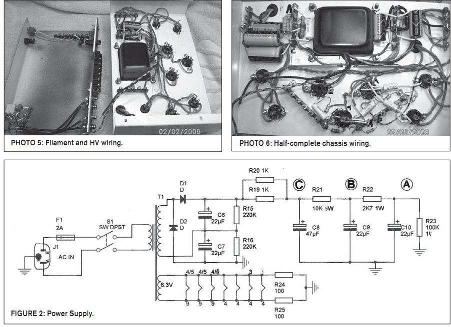
PHOTO 5: Filament and HV wiring.
PHOTO 6: Half-complete chassis wiring.
FIGURE 2: Power Supply.
FURTHER DEVELOPMENT
I have been surfing the DIYaudio forum and was interested in using a constant current source (CCS) for the bias on the output tubes, so I decided to try it in this amp. This requires a few extra parts that are not included in the cost of this project, so I will list them separately, if you want to try it. The only issue with this circuit is that it may push you over $150 (it is close to a wash since you are eliminating two 5W resistors and a 100MF electrolytic per channel). Also, in order to try it, you will need to remove the 2-100 ohm resistors in the filament supply (to ground). (Fig 1 and 2) The 15 ohm resistor sets the current at 80mA total for both tubes (40mA per tube). Center the pot, and then using a DVM, read voltage across the 17 resistors, and set the pot for 40mV across each resistor. Measure alternately across each resistor and balance the two tubes in each channel.
After about one hour of operation, check and reset them. Check periodically.
The formula for figuring the value for the resistor is 1.25 divided by the total current draw for both tubes (in amperes). 1.25/0.08A = 15.637 (15 is close enough)
Once you have calculated the value, you can select the LM317 that fits your application. For this amp I could probably have used the LZ version (size of a small plastic transistor), but since I had a large stock of TO220 317s, this is what I used.
If you want to use this circuit with KT88s, 6550s, and the like, you will need to use the HV version of the 317 (LM317HV).
I was truly amazed at the difference in the sound of this amplifier with modification (special thanks to Bruce H at DIY Audio forums for his tutelage). This mod opened up the soundstage considerably and really helped enforce the bass reproduction.
At this point I am extremely happy with this little "sweetie." The ultimate test was to take it to Larry's (my McIntosh friend). His first impression was that it was "cute," but after we listened to it for 30 minutes he was pretty impressed. When I told him the total cost, his response was "amazement" and an unprintable expletive.
I am pretty confident that any of you can build a similar amplifier at a similar cost. I urge you to give it a try; it just might become one of your favorites.
I am always happy to answer questions and entertain suggestions and opinions from readers.
However, I want to remind the armchair quarterbacks that I am just a hobbyist, not an engineer. If your comments are meant to show how lofty your thought process is, I urge you to write an article, rather than write me.
Also see:
BORBELY RIAA with TUBES REVISITED--The author offers a redesign of this popular phono preamp.