BORBELY RIAA with TUBES REVISITED--The author offers a redesign of this popular phono preamp. By Joe Tritschler
Here's a rework of a fan favorite: a phono preamp that includes new features and improvements.
Borbely RIAA with Tubes, Revisited
In the October 2003 audioXpress magazine, I described a stereo phono preamplifier using 5842 triodes and an equalization scheme that was inspired by an article written by Erno Borbely nearly 25 years ago for The Audio Amateur.
Several readers built 5842 preamplifiers, including a gentleman in the United Kingdom who called it a "living, breathing instrument," for which I'm very grateful. Since that original article, I've made many changes to the unit and present them here. The preamplifier remains the centerpiece of my system and I use it constantly, often playing several records per day.
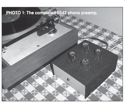
PHOTO 1: The completed 5842 phono preamp.
THE CIRCUIT
Borbely's approach to a phono preamp in 1985 can be described as half-active and half-passive; a linear gain stage up front is followed by a passive low-pass filter for the RIAA 75Ms rolloff and an active shelving equalizer for the 500Hz/50Hz low frequency boost. My preamplifier replaced Borbely's discrete transistor circuitry with two very high-transconductance frame grid tubes, and the result was very good subjective and measured performance. I've elected to keep the basic topology of this circuit intact through all the changes. A common-cathode amplifier stage provides voltage gain at the input, followed by an RC low-pass filter; then a second amplifier stage with anode-follower negative feedback implements the RIAA bass boost courtesy of a series capacitor in the feed back impedance. With only two active devices, it's indeed a very simple circuit.
Design revisions encompass the following: a new biasing scheme and operating point, a redesigned low-frequency section that offers higher overall gain, a modification to the extreme high-frequency response of the preamplifier, and special attention paid to equalization accuracy and component technology. The result is a preamplifier that is a major improvement over the original in both objective and subjective terms.
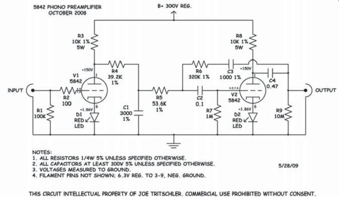
FIGURE 1: Phono preamp circuit.
BIASED OPINION
Rather than a traditional cathode bias resistor with bypass capacitor, each stage of the updated preamplifier (Fig. 1) uses a Lumex SSL-LX5093ID LED to set its cathode voltage, a technique inspired by Morgan Jones in the third edition of his book Valve Amplifiers (available from Old Colony Sound Lab, www.
audioxpress.com). The first time I saw LED bias-circa 1999-in the first stage of a power amplifier, my reaction was to make fun of it. Using a nonlinear device in the very circuit position from which the input signal is derived seemed ridiculous at the time.
Mr. Jones made a very convincing argument, however, so I tried it and listened to the difference. It turned out to be a very significant sonic improvement.
LED bias has pros and cons.
LEDs tend to drop a constant voltage over a fairly wide range of operating current. This means that their dynamic resistance is very low. I extrapolated 137 from the manufacturer's datasheet at the chosen operating point of 15mA and used it in my computations. The significant advantage of this is that a cathode bypass capacitor is no longer needed. The down side is that the constant-voltage behavior more or less constitutes fixed bias, losing the cathode resistor's inherent advantage of providing DC feedback to stabilize the tube's operating point. This is of particular concern with high-transconductance tubes since, by definition, small changes in bias produce large variations in plate current.
As it turned out, I did need to plug in a few different combinations of 5842s to find pairs that biased similarly channel to-channel, but the improvement in sound was most worthwhile. Incidentally, there's nothing special about these particular Lumex LEDs; they were simply available locally in surplus. Morgan refers to "cheap red LEDs" in his book, but I tested a few different types and they do differ slightly in voltage (and presumably resistance), and seem to be very consistent within a given part number.
My theory is that a cathode bypass capacitor is likely to be much more audible than any power supply bypass capacitor.
The reason is that even though the dynamic plate current of a single-ended amplifier stage flows through both of them, any AC voltage developed by the power supply capacitor across its impedance (including nonlinearities and parasitic components) will be attenuated by the amplifier's power supply rejection (which is high in this circuit). Whereas, any nonlinear AC signals appearing across the cathode bypass capacitor are placed right into the input grid-to-cathode signal and amplified. This effect seems most pronounced in high-transconductance stages.
Switching to LED bias in this preamplifier brought out reverb tails and other nuances that had previously been missing, probably due to electrolytic capacitor imperfections. Of all the component changes made, this was the most audible, resulting in a major improvement in detail and a clearer, less-fatiguing sound overall.
MORE GAIN, PLEASE
One complaint with the original 5842 pre amplifier circuit was that it had only about 34dB of gain at 1kHz. This was barely enough for use with a moving-magnet cartridge, provided you were driving a line stage or very sensitive power amplifiers.
Because I prefer not to use a line stage at all if I can get away with it, a few more dB overall seemed a worthwhile objective. The original preamplifier set the second-stage mid-band gain to unity, rising to the required +20dB below 50Hz.
It occurred to me that if I could set the mid-band gain to exactly 20dB below the open-loop gain of the stage by adjusting the feedback network, then every drop of available gain could be squeezed out of the circuit at low frequencies where m aximum gain is required by the RIAA equalization. The result is an overall gain of about 40dB at 1kHz, which is enough to drive my triode monoblock power amplifiers without further amplification. I performed the computations assuming a 100 k-Ohm load on the output, as presented by the stepped Daven attenuators on my power amps.
With a moving-magnet cartridge, the output is within a few dB of CD level, which is close enough for my system. It allows me to switch directly between the two at the amplifiers with only a couple clicks of the volume controls.
ULTRASONIC STUFF
Conspicuously absent from the revised circuit is a shelving resistor in the low-pass filter which was previously used to insert a 50kHz zero into the response, supposedly to compensate for the deliberately limited boost capabilities of record-cutting equalization. The idea, apparently endorsed by many designers, is that this compensation audibly reduces high-frequency phase distortion. I did a subjective comparison between networks with and without the 50kHz zero and concluded that I actually preferred the sound without it.
Worth mentioning is that allowing the HF response to roll off seems to reduce the subjective effect of record surface noise and pops. Given that the interaction between cartridge inductance, cable/arm/preamp capacitance, and input resistance already forms a second-order low-pass filter that has a much greater effect on frequency response than a simple 50kHz first-order low-pass filter during recording, it seems a moot point anyway. Golden-eared audiophiles with ultrasonic hearing (or maybe their dogs) are entitled to their preference, but I no longer believe in implementing this HF shelf.
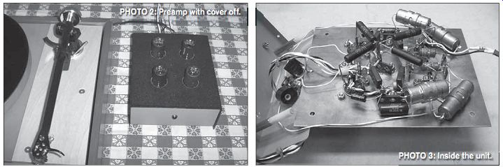
PHOTO 2: Preamp with cover off. PHOTO 3: Inside the unit.
With regard to cartridge inductance and loading, I chopped the cable on my Rega/Origin Live tonearm to about a foot in length and located the preamplifier immediately adjacent to it, greatly reducing shunt capacitance and audibly improving high-end response. Ray Futrell wrote a good article on the subject a few years ago in aX ("The LP Terminator," January 2003). I was able to increase the preamplifier input terminating resistor to 100 k-Ohm with only a slight response peak a little over 20kHz with my particular cartridge.
PARTS IS PARTS
In my original article, I stated that I preferred the sound of carbon composition resistors despite their relatively poor objective noise performance. Several readers took exception to this, mostly on the grounds that they also suffer from poor tolerance and drift. Well, you guys were right: Car bon comps really aren't stable enough for complex equalization networks, particularly those that must be both accurate to a reference standard and precise channel to-channel. I now reserve them solely for restoration of older equipment and occasionally in grid-stopper applications.
I prefer non-inductive precision wire wound resistors by Shallcross, Ultraohm, Mepco, and Daven for their sound and ac curacy, but if you don't have access to them, you can use regular metal films with perfectly acceptable results. For plate-load resistors, I used 7W half-percent non-inductives made by Tepro, but any quality wire wound of at least 5W would work, provided it's within the specified tolerance of 1%.
The blocking capacitors make a subtly audible difference, but I wouldn't lose sleep over it. I happen to really enjoy the sound of extended-film/paper-in-oil Sprague Vitamin-Qs (196P-series) and also use them in my power amps (and even the crossover capacitors on my horn tweeters). But, like the non-inductive resistors, if you don't have a good supply of them, it's certainly not the end of the world. I had some SBE 716P polypropylene film-and-foil "orange drop" capacitors in there for a while and they sounded very good; maybe a little "artificially detailed" for my tastes, but it's an entirely subjective call.
The equalization capacitors are old-style 1% silver micas, which is a very controversial choice. Many folks seem to find them metallic sounding and some engineers have reported hysteresis distortion with them. I've found that placing a large DC bias across them (in this case, the plate voltage of the stage, which should negate any hysteresis effects) makes a world of difference, and they sound truly transparent to my ears. I use the old types which are reportedly made of cleaved sheets of natural mica, as opposed to modern ones which are a ground-up slurry. But again, don't sweat the small stuff. The precision polypropylene film-and-foil types available now would probably work and sound just fine if you don't choose to use micas.
TUBES AND WIRE
The 1980s JAN Raytheon 5842Qs that were very plentiful a few years ago work fine in the second stage of the amplifier, but I had a little trouble with them in the front end due to microphonics. I ended up scavenging some late-60s Amperexes, which were much quieter. Strangely enough, these seem to have much more subjective bass response than the Raytheons, but only in the first stage; probably because the second amplifier stage has a negative feedback loop.
The extra bass is lovely, but this type of thing can drive an electrical engineer crazy.
The short IERC heatsink/shields are nice if you can find them.
Does the type of wire used really make that much of a sonic difference? The engineer in me doubts it at audio frequencies, but, then again, it seems to. I used Teflon insulated silver-plated stranded hookup wire because I had access to it. No question Teflon is much more forgiving toward soldering technique.
Photo 3 shows my preamplifier in its current modified state, still on the same piece of copper-clad PC board material as the original with the same phenolic tube sockets. I have changed nearly every other component. All connections on the board are component-to-component, with the copper cladding forming an excellent ground plane.
POWER SUPPLY
At the moment, I'm using a tube-regulated Gen-Rad laboratory power supply from the 1960s, which is especially nice because it's not mine (thanks, Chris). It provides very well regulated 300V B+ and 6.3V filament supplies, both of which are essential if you don't plan any further power-sup ply decoupling. The preamp draws 60mA from the B+ and 1.2A for the filaments. I included a 1nF silver-mica capacitor inside the preamplifier as a precaution to shunt any rising impedance at RF due to stray inductance in the B+ power supply umbilical, but it worked just fine without it.
MEASURED SPECS
Photo 4 shows the actual measured frequency response of the preamp using a Tektronix SG 505 MOD WQ oscillator and a Tektronix AA 501 distortion analyzer as a precision AC voltmeter. The response is indeed very flat; I didn't need to do any empirical tweaking of the calculated circuit values. The low frequency response is about 1dB underdamped from around 20 to 50Hz, which is likely due to the presence of three capacitors within the second stage feedback loop. My rationale for this design choice is that I preferred the sound with this configuration; maybe it's because both blocking capacitors are subject to negative feedback. Stability is ensured regardless be cause the amp runs open loop at VLF. At 20kHz the response is down a little over 1dB, but it starts to rise again, becoming underdamped by 4dB at 100kHz. This is probably due to the negative feedback loop as well; in this case, an HF pole at the grid of the second stage interacts with an output pole caused mostly by stray capacitance imposed by the test equipment and interconnecting cables, which should be similar to conditions encountered in actual use.
In the middle of the pass band, where it really counts (my use of Edgar midrange horns reinforces my strong belief in this philosophy), the response is flat from 200Hz to 5kHz, with only a 0.1dB crest at the 75µs RIAA turn over point. This is certainly flatter than my (pretty darn flat) speakers. Gain measured 41.2dB in one channel and 41.3dB in the other, and the "A"-weighted noise with inputs shorted is -76 and -75dB, respectively, referred to a typical moving-magnet input level of 4mV. Subjective noise level is negligible; even at very high volume levels, I hear nothing when switching from CD to LP.
LISTENING & CONCLUSION
How does it sound? Well, if a meteor were to crash through my roof and wipe out my entire system, I'd spend the insurance money on parts to build another preamp exactly like this one. But seriously, folks ... I believe this is about the best I can do.
My friends really seem to like it, too--and some of them have very expensive tastes in audio gear. For those who can't afford to build something quite this exotic, there's a much cheaper version of the circuit that sounds almost as good. But that'll have to wait until next time.
---------------
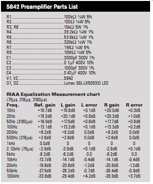
R1 ...100 k-Ohm ¼W 5% R2 ...1007 ¼W 5% R3, R8 ...10 k-Ohm 5W 1% R4 ...39.2 k-Ohm ¼W 1% R5 ...53.6 k-Ohm ¼W 1% R6 ...320 k-Ohm ¼W 1%
R7 ...1M7 ¼W 5% R9 ...10M7 ¼W 5% C1 ...3000pF 300V 1% C2 ...0.1MF 400V 10% C3 ...1000pF 300V 1% C4 ...0.47MF 400V 10% V1, V2 5842
D1, D2 Lumex SSL-LX5093ID LED
RIAA Equalization Measurement chart
(75Ms, 318Ms, 3180Ms)
5842 Preamplifier
Parts List
Freq. Ref. gain L gain L error R gain R error 10Hz +19.7dB +19.8dB +0.1dB +20.0dB +0.3dB 20Hz +19.3dB +20.1dB +0.8dB +20.3dB +1.0dB 50Hz (3180Ms) +16.9dB +17.5dB +0.6dB +17.7dB +0.8dB 100Hz +13.1dB +13.2dB +0.1dB +13.3dB +0.2dB 200Hz +8.2dB +8.2dB 0.0dB +8.2dB 0.0dB 500Hz (318Ms) +2.6dB +2.6dB 0.0dB +2.6dB 0.0dB 1kHz 0.0dB 0 0 0 0 2.12kHz (75Ms) -2.9dB -2.8dB +0.1dB -2.8dB +0.1dB 5kHz -8.2dB -8.2dB 0.0 -8.2dB 0.0 10kHz -13.7dB -14.1dB -0.4dB -14.1dB -0.4dB 20kHz -19.6dB -20.8dB -1.2dB -20.8dB -1.2dB 50kHz -27.5dB -28.2dB -0.7dB -28.4dB -0.9dB 100kHz -33.6dB -29.4dB +4.2dB -29.9dB +3.7dB
---------------------------
THANKS
Many thanks to my father Tony Tritschler, an exceptional audio engineer and loud speaker expert without whom I wouldn't have a system at all; to Duke Fecteau, Bob Jones, Larry Mehal, Curtis Welch, Fred Garber, and all my audio buddies for good times and invaluable feedback; to Roger Hughes at Midwest Surplus Electronics in Fairborn, Ohio, who has been taking IOUs and giving me good-natured grief for almost 15 years now; and to Chris Ivan, a first-rate tech and tremendous source of knowledge from whom I've stolen al most all of my electronic components, and whose hi-fi system I've shamelessly imitated almost entirely.
Also see: AC FILTER ... AND OTHER NOISY ISSUES--Start at your AC power line for better audio ... and video.