AUDIO CLASSROOM, PT. 6B -- This noted audio teacher wraps up his discussion of which circuit to use in your amplifier design.
--------------
By Norman H. Crowhurst
Designing Your Own Amplifier Part 6b: Special Output Circuits
This article originally appeared in Audiocraft, March 1957. 1957 by Audiocom, Inc.
A variant of the pentode cathode follower circuit is the unity-coupled circuit used by McIntosh, and shown schematically in Fig. 11. Half the output load is put in the plate circuit and half in the cathode circuit, using an equal number of turns in each. By cross-coupling the screens, the screen-cathode potential is maintained constant during the audio cycle, as with the straight cathode-follower pentode.
It is important that the screen be tightly coupled to its corresponding cathode. For this reason the screen-and plate winding is wound bifilar with the cathode winding; that is, the turns of both are put on side by side at the same time. Good insulation is needed between these individual turns, since the voltage between them is full B+. DC voltage on the screen will be the same as the plate voltage, as in the ultralinear method of operation.
The drive swing will be a little more than half that required for the pentode cathode follower, since it will be made up of half the plate plus the full grid swing.
The reduction in harmonic distortion would also be about half that obtained in the cathode follower, resulting in about 0.5% without any overall feedback. Source resistance will also be about double that of the full cathode-follower pentode circuit.
CATHODE-COUPLED ULTRALINEAR
Another variant may be regarded as an ultralinear circuit with partial cathode feedback. This is shown schematically in Fig. 12. The proper fraction of swing for the screens is obtained by this cathode winding, and the screens themselves are coupled to a B+ point. This enables a lower B+ to be used on the screens than on the plates, without the necessity for a separate screen winding. The circuit is used in the Bell 2200-C amplifier and also several in the Bogen line.
CIRCLOTRON
The last circuit we shall consider in this article is the Electro-Voice Circlotron circuit, shown in Fig. 13. Batteries are shown for the two separate B+ supplies necessary with this arrangement.
This circuit is named for the loop (or circle) consisting of the two output tubes and the two B+ supplies. When the bias on each output tube is identical, which occurs at the quiescent condition, the current around the entire loop is uniform. But when one grid is driven positive and the other negative, the currents passed by the two output tubes differ, as do the proportions of total voltage drop across each tube. Then the transformer connected between cathodes (which previously were both at the same potential) carries a load current.
The tubes here are acting as pentodes because cathode and screen are separated in each case by a constant potential.
They are virtually in parallel, each cathode being connected to the other plate, with the output transformer being connected across the whole combination.
This is where this circuit differs from the normal push-pull arrangement, in which the two tubes virtually feed the load in series. The result is that the plate-to-plate (or cathode-to-cathode-whichever you prefer to call it) load has a value one quarter of that proper for the normal push-pull output.
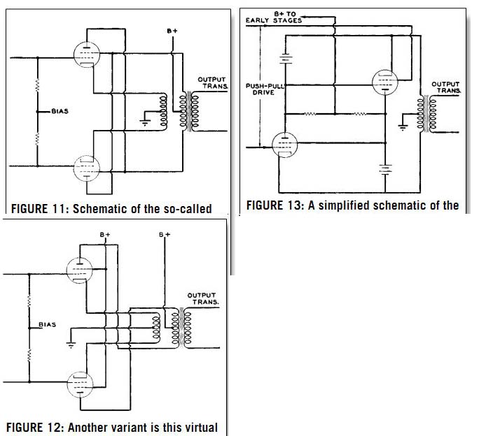
FIGURE 11: Schematic of the so-called unity-coupling circuit. Here the tubes are operating as pentodes or tetrodes, with half the amount of feedback achieved by the cathode-follower circuit, Fig. 7.
FIGURE 12: Another variant is this virtual ultralinear arrangement, employing partial cathode coupling. For 43% equivalent tapping, the cathode winding should have 43% of the total equivalent primary turns, while the plate winding should have the remaining 57%. This arrangement enables the plates and screen to operate at different DC potentials for in creased power, if desired.
FIGURE 13: A simplified schematic of the Circlotron circuit. Batteries have been shown in place of the two separate B+ + supplies necessary for the system, both of which are isolated from ground.
The B+ supply for the earlier part of the amplifier is achieved by putting two resistors in series between the two B+ points and taking the supply from the center point. Ground is provided by the center tap of the output transformer.
If the output-tube grids were re turned to ground, the arrangement would be somewhat analogous to a cathode-follower circuit, because the drive at the grids would have to provide the grid swing in addition to the output swing on the cathodes. This is partially offset in the Circlotron circuit by re turning the B+ for the push-pull drive stage to the positive voltage from the opposite output tube in each case. It is difficult to know whether this should be called a positive feedback or a reduction in negative feedback.
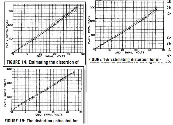
FIGURE 14: Estimating the distortion of 5881 tubes as triodes from the transfer characteristic: the peak fundamental is about 158V, while the peak harmonic is about 5.5V; for this the peak ratio represents 3.5% harmonic.
FIGURE 15: The distortion estimated for the pentode (tetrode) operation: peak fundamental is 280V, and peak harmonic 8V, for about 2.85% total.
FIGURE 16: Estimating distortion for ultralinear operation, from the transfer characteristics: peak fundamental 288V, peak harmonic 11V, and total harmonic distortion, 3.8%. These figures give peak summation in each case, and so differ from the RMS text analysis.
ESTIMATING DISTORTION
So much for a number of popular varieties of output circuit. One thing more is needed to complete this article: a graphical way to estimate the distortion. This is illustrated in Figs. 14, 15, and 16 for the triode, pentode, and ultralinear operation of the 5881 shown in Figs. 2, 6, and 9 of Part 6a.
In each case the transfer characteristic is plotted, plate swing vertically against grid swing horizontally. Only one half of the characteristic is plotted because, being push-pull, the two halves are symmetrical. The negative swing would be exactly similar, but to the left and downward from the zero points.
The curve is plotted and then a straight line is drawn from the origin to pass through the curve in such a way that the excursions above and below the straight line (as determined by further dotted lines parallel with it) are equal on both sides.
This method of measurement does not determine the relationship between RMS harmonic and RMS fundamental, but between peak harmonic and peak fundamental. If only one harmonic is present, the two figures will, of course, be identical, but invariably more than one harmonic is present. Then the usual trend is that the peak relation ship gives a higher percentage harmonic than the RMS relationship.
Although this means that the figure obtained from the construction will not agree with that obtained by the usual forms of measurement, it does mean that it gives a better practical indication of the annoyance value of the distortion, because multiple harmonics-especially high-order ones-are much more annoying than a single lower order harmonic.
Figure 17 is given to aid in identifying various harmonics from the third to the ninth, assuming they are present as separate entities. Here the fundamental is represented as being removed and the deviation shown horizontally.
Compare Fig. 16 with Fig. 17: the point where the curve crosses the center line should be 0.866 of the total excursion for the harmonic to be pure third.
In Fig. 16 the crossover point is a little nearer the top than this, meaning that there are some higher-order harmonics, although quite small in amplitude.
On the other hand, the crossover point shown for triode characteristics in Fig. 14 is considerably lower than 0.866, indicating in this case that there are probably components of fifth, seventh, and ninth.
The multiple curvature of the transfer characteristic in Fig. 15 can only be explained by the presence of harmonics at least up to the seventh.
CONCLUSIONS
Now, having studied different kinds of output circuits somewhat, are we in a better position to assess which kind of output--triode, pentode, or ultralinear--is the best one to use? Perhaps it would be more accurate to say that now we can see why there is so much confusion on the issue and why different individuals prefer different circuits.
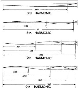
FIGURE 17: This chart is to aid in identifying the various odd-order harmonics present from the shape of the transfer characteristic. The fractions give the points at which the curve should cross the straight fundamental line, when only that harmonic is present in the signal.
From our previous discussion of amplifier design we learned that the circuit should be designed to give the lowest possible distortion before any feed back is applied (and if possible this distortion should be of low order). Com paring the three methods of operation for the 5881:
The pentode seemed to show the lowest distortion, but the dominant components were third and seventh. Additionally, the fact that the load line goes across crooked characteristics means that any load deviation from a straight line of specific value will cause considerable variation in the distortion produced.
The ultralinear circuit, with 3.3% almost pure third-harmonic distortion, and characteristics whose shape will not cause appreciably increased distortion when the load line deviates from its particular resistance value or goes reactive, is the most practical circuit of the three.
The triode-connected arrangement strikes an intermediate position, with 3.3% third- and 1.25% fifth-harmonic distortion. Variation of resistance value over a limited range will not seriously affect the distortion percentage, but re active components are a little more likely to do so.
The unity-coupled arrangement achieves a high output from a pentode without the same loss of gain that would be necessary when cathode coupling.
Because of the extremely tight coupling between cathode and plate-screen circuits, it is possible to operate this amplifier into the grid-current region and still maintain a low order of distortion.
The partially cathode-coupled ultra linear circuit is another good variant, but requires careful attention to trans former design.
The Circlotron obviates the necessity for highly critical design of the output transformer. What could prove to be a further liability in this arrangement is the fact that the whole of the two B+ supplies constitute part of the output circuit. This means they can contribute to the frequency response or stability characteristics of the entire amplifier.
---------
Also see:
AUDIO CLASSROOM, PT. 6A: A classic text from one of the great teachers of amp design