By Norman H. Crowhurst
Designing Your Own Amplifier: Part 6a: Special Output Circuits
This article appeared originally in Audiocraft, February 1957. 1957 by Audio com, Inc.
The part of amplifier design that has always posed the biggest problem is the output circuit-how to get enough power with low distortion and a satisfactory value of source resistance, or damping factor. To illustrate this problem in more detail, we will try various methods of connection for the 5881 tube as a basis for comparison.
TRIODE CONNECTION
Consider first the straight triode connection shown in Fig. 1, with a plate voltage of 400, a fixed bias of 45V, and a plate-to plate load of 4,000 ohm. This is the condition known as Class AB1, or "low-loading." The reason for the second name is that the load resistance is much lower than the original value intended for Class A operation; its advantage is that a greater maximum output can be obtained.
Figure 2 shows the load line applied to the characteristic curves of a single tube.
The solid straight line represents a resistance of 1,000 ohm, which is how 4,000 ohm plate-to-plate appears to one tube; the dashed curved line represents the load line for this tube, the other tube being complementary so as to produce the straight line as a composite. From the composite line, we can obtain plate-voltage swings (for positive grid excursions from the 45V bias point) of 48V, 104V, and 162V, respectively, for grid swings of 15V, 30V, and 45V.
A peak plate swing of 162V across the load resistance of 1,000 ohm represents an average power output of The tube manual quotes a value of 13.3W for the same operating conditions, which is near enough to the same answer.
A mathematical analysis of this amplification, based on the three points obtained, gives the distortion figures as 3.3% third and 1.25% fifth harmonic. The method of deriving these figures involves trigonometry and is too involved to go into in detail here. Taking the RMS combination of these two components, the total harmonic distortion will be v(3.3) ? + (1.25) ?= about 3.5%. The tube manual quotes 4.4% for 13.3W. Later in this article we will show a simple graphic method of estimating the amount of distortion.
We can calculate the source resistance from the slope of the -45V curve where it intersects the dashed load line. If we draw a tangent through this point of the curve it will pass through 340V at 0mA, and 620V at 100mA. This represents a resistance of 2.8k. As the slope of the composite curve will be twice as steep at this point, this will become 1.4k at the center point on the load line. This is referred to one half of the output winding and, referred to the 4,000 ohm plate-to-plate, would be four times this value, or 5.6k. So the source resistance, in this case, is about 1.4 times the load resistance.
To produce an output stage that is acceptable by modern standards, we must reduce the amount of distortion (quoted as 4.4%), and also the source resistance. This output stage requires a pk-pk swing on each grid of 90V, for which purpose the previous stage should also be of a push-pull variety, using a low-mu twin triode. Therefore, the grid drive to this previous stage, without feedback, must be of pk-pk amplitude somewhere between 5 and 10V.
To obtain adequate feedback over the two stages (which is recognized to be an ideal arrangement from a stability stand point), we must inject some 10 to 50V pk-pk in the cathode circuit of this drive tube, according to the amount of feedback considered desirable. The cathode resistor of this stage, across which the feed back voltage must be produced, is probably on the order of 2k.
If we take the feedback from the plate circuit of the output tubes, the resistors necessary to produce such a large voltage on the cathode of the drive stage must be physically large enough to dissipate 1 or 2W. More important, the output tubes will no longer have 13W available for the external circuit, because 1 or 2W are expended in the feedback.
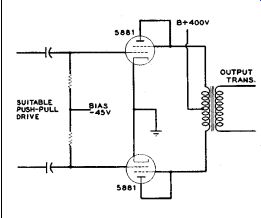
FIGURE 1: Schematic of output circuit, using two 5881 tubes as triodes.
Note that screens are connected to plates.
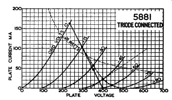
FIGURE 2: Characteristics of 5881 tube triode connected, with load line
to illustrate this method of operation. The solid straight line is one
half of the composite line for a plate-to-plate resistance of 4,000 ohm.
The dotted curved line represents the load component of this composite
on the single characteristics shown. Dots on the composite line are projected
downward from the intersection with the curved line.
The curved line is plotted in the manner described in Part 4a (GA 3/00). Also shown is the maximum dissipation curve at 26W.
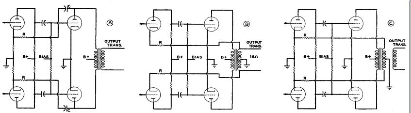
FIGURE 3: Different methods of applying feedback over two stages: at
A, the feedback is taken from the plates of the output tubes, requiring
a relatively large value of the blocking capacitor, C. Resistor R must
dissipate a considerable proportion of the output power to achieve the
desired amount of feedback. At B, the feedback is taken from the 16 ohm
winding of the output transformer, which is here center-tapped. Resistors
R may be necessary to provide the correct bias for the drive stage, but
will not contribute to the feedback performance appreciably. C is a better
arrangement than either A or B, but this requires a special output transformer.
If we consider taking the feedback from the transformer secondary, using the 16 ohm winding, which is usually the highest impedance available, the pk-pk voltage developed by 13W across 16 ohm is just over 40V. This may be sufficient for the purpose, but it is evident that no series resistor can be used, so the 16 ohm winding must be directly coupled to the cathode of the drive stage. This, too, can involve undesirable complications.
The problem appears to arise with tri odes because the plate-circuit impedance is too high, and the secondary-circuit impedance is too low. A compromise some manufacturers have adopted utilizes a special feedback winding with an inter mediate number of turns. This obviates the necessity for the large-value blocking capacitor, and reduces the power dissipation involved in feeding back from the plate circuit, yet permits use of some isolating resistance.
The foregoing comparison is illustrated in Fig. 3. An obvious snag is that a special transformer must be procured. Consequently, this method is readily available only to manufacturers having facilities for producing transformers with custom specifications. For that reason, we will not pursue the discussion of this arrangement further.
Before leaving it, however, we may add that the method is equally applicable to pentode or other methods of connection as output stages. As might be expected, because the pentode has a higher gain than a triode, the previous stage needs to give much less swing to obtain maximum output, and this in turn means that a smaller voltage, tapped off from the output, will give a corresponding amount of feedback. What offsets this fact is the high plate resistance of the pentode, which means that a much larger amount of feedback must be used to obtain a satisfactory damping factor.
CATHODE-FOLLOWER OUTPUT
The next circuit we shall consider here is the cathode follower, because this has several variants that we can discuss later in the article. Figure 4 shows the arrangement of the cathode follower for a triode output.
Since the plate-voltage swing is now developed across a load connected in the cathode circuit, the grid must be driven by a voltage made up of the former plate-voltage swing added to the normal grid swing given by the load line. This is a total swing in each direction of 162+ 45 = 207V: a pk-pk drive of 414V for each tube. A drive stage using our assumed 400V plate supply would obviously need a transformer to produce this much voltage.
The stage now requires a grid-voltage swing of 207V to produce a grid-to-cathode swing of 45V, which represents a feedback ratio of 4.6. Thus the original distortion figure of 4.4% will be reduced to less than 1%.
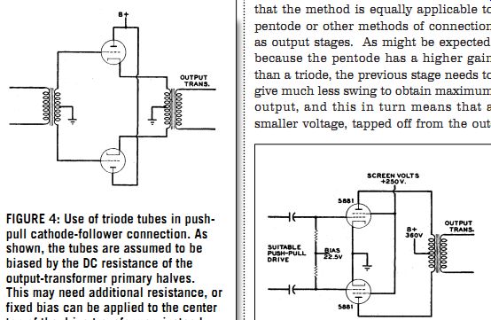
FIGURE 4: Use of triode tubes in push pull cathode-follower connection.
As shown, the tubes are assumed to be biased by the DC resistance of
the output-transformer primary halves.
This may need additional resistance, or fixed bias can be applied to the center tap of the drive transformer, instead of returning it to ground. A drive trans former is the only simple way of getting sufficient swing for a cathode-follower stage without using a higher B+ for the drive stage.

FIGURE 5: Schematic of output circuit, using 5881 tubes as tetrodes
(commonly called pentodes, because of the similarity of the operating
characteristics).
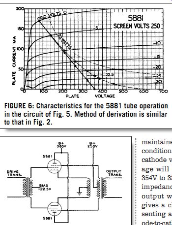
FIGURE 6: Characteristics for the 5881 tube operation in the circuit
of Fig. 5. Method of derivation is similar to that in Fig. 2. FIGURE
7: This circuit arrangement can be used to operate the output tubes
as pentode (strictly, tetrode) cathode followers, with the same operating
conditions as shown in the load line of Fig. 6.
Now, how about the source resistance? Consider the operating point for 15V positive swing; that is, the -30V point on the composite load line.
This gives 354 plate volts at 48mA. A negative grid swing of 15V from this point brings us to the operating point where the resultant plate current is zero.
Assuming that the actual volts on the grid are maintained the same (that this change of condition is brought about by a change of cathode voltage) the plate-to-cathode volt age will now have dropped 15V, from 354V to 339V. Referred to the 1,000 ohm load impedance presented by one half of the output winding, the source resistance gives a change of 15V for 48mA, representing about 312 ohm. This is 1,250 ohm cathode-to-cathode; the source resistance is a little less than ¹/3 the load.
PENTODE CONNECTION
Figure 5 shows a pentode connection of this same tube. The composite load condition for one tube is shown in Fig. 6, assuming a screen voltage of 250 with a plate voltage of 360. The nearest values to this given in the tube manual listing are a plate voltage of 360 and a screen voltage of 270, with the same bias voltage of -22.5.
Tube-characteristic curves for a screen voltage of 270 are not available, so we compute the results from the tube curves for the screen voltage of 250, using the plate-to-plate resistance of 6.6k quoted in the tube manual.
The load-line slope is drawn at 1.65k.
Peak plate-voltage swing is 280, which represents an average output of 23.7W, compared to the 26.5W quoted in the manual. This seems to be consistent with the difference in screen voltage from 250 to 270.
A mathematical computation from the points on the given load line yields harmonic distortion figures of 2.5% third and 1.5% seventh, a total of 2.9%. The tube manual gives 2% for the screen voltage of 270.
To quote a source resistance for this form of output is somewhat meaningless, because the slope of the tube characteristics varies all the way up the load line. We can, however, apply the cathode-follower connection to the pentode circuit by the arrangement shown in Fig. 7, in which case the feedback tends to hold the source resistance more constant. Consider a 2.5V change near the operating point.
From the characteristics, it may be seen that this gives a current change of 22mA, for a voltage change of 2.5V, representing an impedance of about 114 ohm, or 450 ohm cathode-to-cathode.
In this case the input swing required is 280V cathode swing, plus 22.5V grid-to cathode swing, giving a total of 305, or 610 pk-pk for each tube. This is an even ...
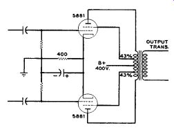
FIGURE 8: Schematic of circuit for operating 5881 tubes
in the ultralinear circuit. This particular arrangement uses cathode
bias, but fixed bias can also be used. As explained in the text, the
ultra linear operation is not so critical.
...larger requirement than for triode operation. But since we are using a 305V peak to obtain a 22.5V effective swing, the feed back ratio is 13.5. This means that the distortion figure of 2.9% will be reduced to about 0.22%.
To operate a pentode as a cathode follower, the screen voltage must swing exactly with the cathode voltage to keep the cathode-to-screen potential constant. In a voltage-amplifying stage, this could probably be accomplished by decoupling the screen to cathode rather than ground, but in a power stage the only feasible way to achieve this end is by using a transformer with an extra winding, as shown in Fig. 7.
The cathode and screen windings should be extremely tightly coupled to avoid any difference in voltage between cathode and screen at any point in the frequency spectrum. A difference in voltage at this point would result in serious distortion, because of the extreme nonlinearity of screen current with screen voltage.
To the best of my knowledge, the cathode follower pentode output is not used. But we will consider later a circuit that is used, and which may be considered to be derived from it.
----------------
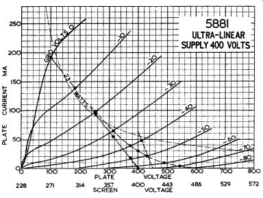
FIGURE 9: Tube characteristics for ultralinear operation with a supply
of 400V (plate or screen to cathode). The curves were plotted by reducing
the screen voltage from 400 by 43% of the reduction used for the plate
(increase same way). Composite and individual load lines are also shown,
as for triode and pentode operation.
ULTRALINEAR CIRCUIT
The third operating condition for output tubes is becoming popular for good reason. From discussions of triode and pentode operation, it seems that neither is exactly ideal. It is obvious that a method of operation lying somewhere between these two extremes might be optimal. This is precisely what the ultralinear or tapped screen method of operation achieves.
The circuit is shown in Fig. 8. Static tube characteristics for this connection, as published by Tung-Sol, are illustrated in Fig. 9.
Ultralinear operation is fairly simple to understand by comparison with triode and pentode operation. In a pentode circuit, the screen voltage is held constant, while the plate voltage is allowed to swing according to the grid-voltage drive. In a triode-connected pentode, the screen is strapped to the plate; hence, its voltage swings by precisely the same amount as the plate voltage. Ultralinear operation splits the difference and, in the case of the curves shown in Fig. 9, the screen voltage swings by 43% of the plate voltage.
This is achieved in practice by using 43% taps on the plate winding for connecting the screens. The value of the optimal tapping for different tube types will vary somewhat, but 43% has been found ideal for quite a variety of tubes. The ultralinear circuit (Fig. 8) uses automatic bias, so the bias will change somewhat from zero to full output.
The sloping dashed line in Fig. 9 shows the condition for zero signal. The slope of this line represents a resistance of 800 ohm.
Bias-resistor value is actually 400 ohm, but since the current from both tubes passes through it, this can be regarded as representing 800 ohm per tube. The quiescent operating position is thus found to be about -40V bias, with almost 50mA plate current in each tube.
Bias at the maximum drive condition rises to about -45V. The plate current swings from 30mA per tube, or a 60mA total (where the cycle passes through the operating point), to a peak of about 190mA, giving an average of about 115mA. This produces 46V across 400 ohm.
The solid load line in Fig. 9 represents a plate-to-plate resistance of 6.5k (or a resistance for the single plate of 1.625k).
The peak plate-voltage swing, 300V, produces an output power of 28W, which is higher than either the pentode or triode method of operation.
Distortion is found to be about 3.3%, al most pure third-harmonic. It may be wondered at this point why such a method of operation is called "ultralinear," since the distortion is not appreciably better than either of the other methods of operation.
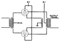
FIGURE 10: Schematic of circuit for operating tubes as ultralinear cathode
followers. For 43% equivalent tapping, the screen winding must have 57%
of the turns in the cathode winding. Extremely good coupling between
the cathode and screen windings is essential.
What the simple figure of distortion does not indicate is how tolerant the circuit is of different impedances.
Compared with triode operation, this arrangement gives more than twice the power. Compared with pentode operation, the increase in power is not so great, but the performance is almost as independent of load as with triode operation. The composite characteristics, if drawn in full, would prove to be much nearer to a set of parallel straight lines than any of the other methods of operation, with the result that this circuit is not critical of inductance components in the load. That is very important in the practical working of the circuit, although it may not be so important when the amplifier is tested with a resistance load.
It would, of course, be possible to operate the ultralinear circuit as a cathode follower, by so coupling the screen that its voltage swings by 57% of the cathode swing while the plate voltage is connected to B+, as shown in Fig. 10. This would require an input drive of 300 + 45 = 345V peak, or 690V pk-pk, which is even more than the drive required for pentode operation. The feedback ratio is 345/45 or 7.67, which would reduce the distortion to less than 0.5%.
The source resistance as a cathode follower can be obtained by considering 5V excursion from the operating point at full output. This is 18mA for 5V, or about 280 ohm. There would be about 1,100 ohm cathode-to-cathode, or about one-sixth of the load resistance. The ultralinear circuit operating normally will have over 7½ times this value, or about 1.25 times the load resistance. As described in Part 5 (GA 6/00), this would be a good starting point for applying overall feedback, and it would be quite permissible to use, say, 20dB of overall feedback to achieve a damping factor of about 8.
Also see:
AUDIO CLASSROOM, PT. 6B This noted audio teacher wraps up his discussion of which circuit to use in your amplifier design.