DEPARTMENTS -- monthly regulars.
-------
- EDITORIAL: Building beauty
- AUDIO NEWS: What's new on the audio market
- MAIL/Feedback: Readers speak out
- BOOK REVIEW High-Power Audio Amplifier Construction Manual
- GLASS SHARD: Experience the best features of auto and fixed bias.
- NEW CHIPS ON THE BLOCK: AKM Semiconductor AK4112A.
- MUSIC CORNER: Are musical impressions, like diamonds, forever? Your chance to sound off.
- TEST TRACKS: Readers' favorites to test audio systems.
-------
Editorial
Building Beauty
By Edward T. Dell, Jr.
I once had the good fortune of standing in Meijii Park in Tokyo on Meijii Day, a national celebration throughout Japan.
One of the many ceremonies taking place was a demonstration whose name I never discovered. A large crowd gathered before a rough, raised platform, with a roof of straw with a railing surrounding the floor area, about waist height for a dozen or so boys dressed in formal kimonos.
An old gentleman was master for the ceremony, which was, apparently, a competition among the participating boys. The master called each of the boys in order. For each of them he placed on the railing a bundle of straw, approximately 3” in diameter.
In turn, each was handed what appeared to be a very sharp, two-edged sword about three feet in length. In a clearly defined ceremonial set of motions, the boys moved the sword from behind, up over their heads, and down into the straw bundle.
The object of the exercise, I was told, was to cut the bundle into two equal pieces, leaving one straw uncut. Nearly everywhere you look in Japan, there are examples of what, to my eye, can only be evidence of some national habit of a consistent, unremitting care for precision and for beauty. I doubt anyone will discover an aesthetic gene in the current classification of the human genome, but if someone does I will not be surprised. I would also not be surprised if it turned out to be a national trait in France as well as Japan.
One of my pleasures as editor of this publication is the magazine exchange with an extensive list of audio periodicals worldwide. In many avocations this would not be very useful, because of the language barrier. Happily, in electronics, there are schematics whose symbology is universal-or nearly so.
My monthly mail includes two periodicals of especial interest.
One is Revue du Son, et du Home Cinema edited by the legendary Jean Hiraga. What is so surprising in this periodical is the style and design of the equipment, of which the magazine re views an impressive quantity each issue. Hiraga keeps track of the major moves in the home audio area, with especial attention to tubes, and each month features a home theater installation, but also publishes at least one article per issue on amateur construction.
This is doubtless a holdover from his days as the editor of L'Audiophile, renowned for innovative articles and ideas on vacuum tubes long before the present revival took place.
The French undoubtedly hold the title for unusual design in the audio field, especially as regards loudspeakers. A great many are fairly pedestrian boxes, but when a show opens, the most eye-opening surprises are usually in the speaker category.
The other magazine of note is MJ (Musen to Jikken translates roughly as Audio Technology). This 240-page monthly periodical has been around since the end of WWII and is predominately dedicated to DIY audio in all of its forms. It pays much attention to new products as well, but also devotes two pages monthly to a tube museum.
Most startling about the content of MJ are the extensive construction features. They are not only of great variety--a recent issue included ten DIY projects-but the majority are also indistinguishable from commercial products. A good example graces the pages of the first issue of audioXpress from the pen and hands of Satoru Kobayashi.
This is not a junk box project and the author will have absolutely no spouse acceptance problem, I would guess.
Beauty is not an accident-and especially not in audio equipment we build with our hands. The Japanese do not have an exclusive claim on component beauty, however. In that same issue, note Tom Perazella's beautiful ribbon speaker. Beauty and aesthetics are not cheap, however.
I do not know what these projects may have cost their authors, but the primary ingredient is a commitment to how the finished device looks. We fortunately live in a time when special ser vices abound in metal cutting, finishing, and engraving, not to mention exotic woods and high-tech construction aids. Such things are not cheap, but they can lend a quality to the finished product which can add a lot to the value and satisfaction we derive from the undertaking.
The aesthetic dimension requires a commitment to the idea, to begin with.
Then follows the time required to re search what might be possible in building any audio device. The computer is also a powerful adjunct to audio construction, where the web offers accessibility to almost any materials or ser vices the builder might want. The CAD capabilities of even inexpensive pro grams to aid physical design are miles beyond what was possible even a decade ago.
Many of you reading this page have specialized knowledge about such ser vices, materials, tools, and the like.
Your shared ideas can enrich the work of every amateur in our group. I hope 2001 can be a year when we do a lot of thinking about the aesthetics of what we build. Those of you who have built a project you are proud of, but perhaps don't wish to write extensively about it, are encouraged to take some photos, write a caption for each, and send them along for publication in these magazine pages.
-E.T.D.
============
Audio News
IKONOKLAST
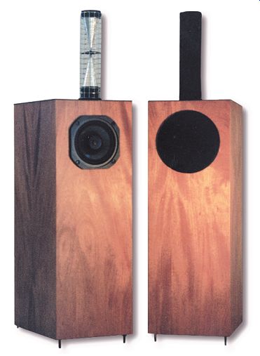
Ikonoklast is a small (35”H × 8¼”W × 12”D) 2-way floor-standing system made to reproduce powerful deep bass using only a 5¼” midrange driver. The Ikonoklast has a sensitivity of 95dB/2.83V/m for use with very low powered amplifiers, such as vacuum tube single-ended triodes. It is finished in 2-ply hardwood veneer. Warren Gregoire & Associates LLC, 229 El Pueblo Place, Clayton, CA 94517, 1-800 634-0094 or 925-673-9393 (international), FAX 925-673-0538, website: www.warrengregoire.com.
OCTAL 6
Mapletree Audio Design is offering a new line-level preamp kit called the Octal 6.
It is the first in the Hollow State Club Series, which features vacuum tube audio components with unique layouts and features, designed by Dr. Lloyd Peppard, a retired Professor of Electrical Engineering. The Octal 6 is a dual-circuit stereo line-level preamplifier employing six octal tubes, permitting any of three input sources to be switched to a shunt-regulated push-pull (SSRP), a common cathode/cathode follower circuit, or a passive path. The kit includes all parts, hardware, wire, solder, NOS tubes, a punched and painted chassis with brass trim, and a 40-page illustrated step-by-step instruction manual. Mapletree Audio Design, RR1, Seeley's Bay, Ontario, Canada K0H 2N0, (613) 387-3830, hollowstate.netfirms.com, e-mail: peppardl@post.queensu.ca.
PARTS EXPRESS CATALOG
Parts Express, a full-line distributor of electronic parts and accessories for the consumer electronics industry, the technical hobbyist, and the commercial or residential installer, announces the release of their comprehensive, 308-page catalog. They stock a selection of raw loudspeaker drivers for home and automotive applications, home theater and home automation products, alarm systems for home and auto, mobile video, tools and technical aids, test equipment, computer accessories, chemicals, telephone products, wire, connectors, instructional books and videotapes, speaker design software, cellular phone accessories, stage lighting, and pro sound equipment. Parts Express, 725 Pleasant Valley Drive, Springboro, OH 45066-0611, 1-800 338-0531, www.partsexpress.com.
MK 10 MICROPHONE
Gold Line introduces the multi-purpose MK 10 omnidirectional measurement/recording micro phone, which is designed for ultra-flat frequency response. The MK 10 features a ½”-diameter pre-polarized condenser capsule with an omnidirectional polar pattern, so it is ideal for certain studio and live recording applications such as music ensembles, pianos, and choirs.
It has also been included in Gold Line's "Prokit" Measurement System.
The MK 10 has a frequency range of 20Hz 10kHz ±1dB or 10Hz-20kHz ±2dB, a maxi mum SPL of 128dB, and low self-noise. Each mike comes with a serial number, individual frequency plot, foam padded carrying case, and mike clip. The housing is machined brass with matte silver finish. Gold Line/TEF, Box 500, West Redding, CT 06896, (203) 938 2588, FAX (203) 938-8740.
VIRTUAL ELECTRONICS LAB
Protel International Ltd. announces the release of Circuitmaker 2000-The Virtual Electronics Lab. This new version of Circuit maker software now provides complete schematic design, simulation, PCB layout, and autorouting in one box. New features include a new waveform viewer, a new device browser, and a streamlined user interface for easier ac cess to various features.
Circuitmaker 2000's Professional Edition PCB layout editor (formerly TraxMaker PRO) also includes a new rip-up and retry maze autorouter. Circuitmaker 2000 allows a designer to capture a design, perform advanced circuit simulation, analyze the operation of a circuit, and complete the design and testing with full featured PCB design and layout capabilities. It is available in both Standard and Professional editions. Protel International, Level 3, 12a Rodborough Rd, Frenchs Forest NSW Australia 2086, +61 2 9975 7710, FAX +61 2 9975 7720, website: www.protel.com.
KT-88 AMPLIFIER
Accurate! Sound Labs (a Division of Accurate Electronics) announces a new line of high-quality imported tube audio amplifiers.
One model features the KT-88, driven as a Class-"A" triode mode, monoblock amplifier.
Very detailed highs and balanced lows, as well as extensive quality control and testing facilities ensure hassle-free performance from every unit. Accurate! Sound Labs, 6692 Brockton Ave., Riverside, CA 92506, (909) 686-6550, FAX (909) 686-6536, accuratesoundlabs.com.
------
TRANSCENDENT SOUND PREAMP KIT
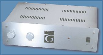
Transcendent Sound announces its entry into the kit market with the Grounded Grid Preamp kit.
The unit is based on a simple yet sophisticated wide band gain stage, which is featured in the book Audio Reality by Bruce Rozenblit. Performance is flat from 5Hz to 300kHz with harmonic distortion less than .02%. The preamp encompasses a "purist" approach with a three position selector, volume control, and power switch. The cabinet includes a brushed stainless steel lid with hand grained and etched faceplate. Transcendent Sound, PO Box 22547, Kansas City, MO 64113, (816) 333 7358, FAX (816) 822-2318, www.transcendentsound.com.
=============
PHONO PREAMP
As a regular reader of GA, I have enjoyed your magazine and built sever al projects straight from the articles, including my own phono preamp. My goals were: two stages, no global feedback, and low output impedance. The starting point was a textbook two-stage, passive-equalization circuit that uses no electrolytics.
I replaced the usual cathode-follower output stage with Rickard Berglund's asymmetrical mu follower (GA 1/93, 1/94).
The low output impedance allows the use of a 10k-ohm volume pot. I optimized net work resistors R6 and R7 for correct response using Norman Koren's SPICE techniques (GA 2/97, 4/97). The overall gain is 36dB at 1kHz.
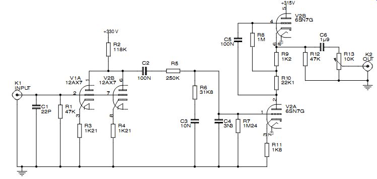
--------------- FIGURE 1: Phono preamp circuit.
The supply voltages in Fig. 1 are not critical and represent the working voltage after soft-regulating 450V down to 400V followed by 5k-ohm pi filters. The 6SN7 draws 6mA and the 12AX7 sections draw 1.5mA each.
Many possibilities for variation exist.
Bypassing the cathodes on V1 will in crease gain by 4dB. In the first stage, you can use other low-noise, high-gain tubes, such as the 6SL7 for an all-octal preamp. I encourage other builders to incorporate their favorite tubes.
I chose the 6SN7 for its combination of low noise and high plate dissipation.
Rickard Berglund's articles have many more examples. Be careful not to exceed the heater-to-cathode limit on the upper section of the asymmetrical mu follower.
SPICE makes it easy to check this and other "what if" scenarios quickly.
Jim Ryan Baltimore, Md.
GROUND LOOP FIX
I just finished reading the Jensen ISO-MAX product review (AE 6/00). Jensen undoubtedly makes fine products, but it's possible to cure CATV/antenna ground loop (hum) problems at far lower cost than the $50 price of Jensen's ISO-MAX CATV Ground Isolator.
I've done this many times by simply connecting a couple of 10nF or 4N7 ceramic disc capacitors in series with the shield and center conductor of the coaxial cable to the antenna input connector of an FM tuner or receiver. It's important to keep capacitor lead lengths near zero, and choose capacitors marked 500V or higher for the sake of reliability.
For a portable capacitive isolation device, I mount a pair of female F fit tings in opposite walls of a small plastic box and bridge them together with the capacitors. Lead length for the shield connection can be excessive in this case, so I use long flat ground lugs to reach the capacitor body with mini mum lead inductance.
Mike Hardwick Decade Engineering; Turner, Oreg.
PREAMP DESIGN
Robbert ter Haar's interesting phono preamp project ("The True Realism Preamplifier," GA 4/00, p. 18) is one that I may well chose to build, but there is one critical issue that was not addressed. What is the gain ? To the experts in electronics, I'm sure it is obvious. It isn't to me. I need upwards of 60dB for my cartridge.
G. Max Carter; Cascade, Colo.
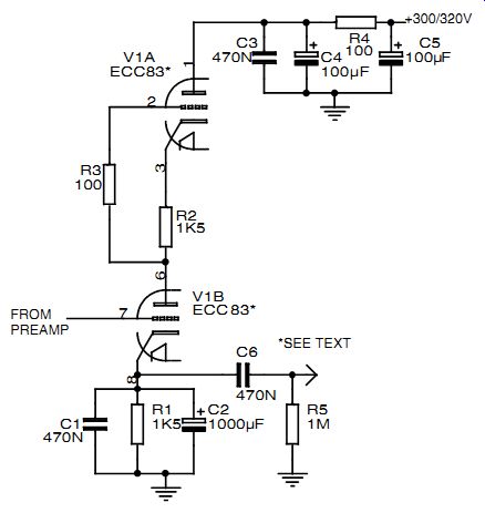
---------- FIGURE 2: Line amp circuit.
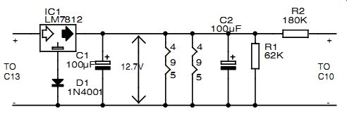
FIGURE 3: Stabilization section.
Robbert H. ter Haar responds:
Thank you for your interest in my unorthodox preamp design.
The gain of the amplifier depends on the tubes you use. With the ECC83 you can expect a total gain of around 46dB; for the ECC81, you will have a gain of approximately 41dB.
I am somewhat surprised about your need for a 60dB gain in the preamp. I am using the DENON DL-103LC II, which has an out put voltage of approximately 0.25mV (1kHz 50mm/sec). The output voltage of the preamp is now almost similar to my CD player.
To make an extra gain of approximately 20dB, I suggest putting the line amplifier in Fig. 2 after your preamp. The tubes for this design are the ECC82s. As you see, you can connect this section on the same power supply as the preamp. For the filaments, you need to add a third stabilization section ( Fig. 3). It is also advisable to increase the filament current transformer from 2.5-3.5 amp to reduce the heat of the transformer and therefore extend the life of all components around this transformer. Please also refer to the power supply schematic ( Fig. 3) in my preamp article.
Mr. ter Haar has written a very interesting article. However, he has no voltage ratings on the capacitors. For example, can I assume C3 and C4 to be low voltage ?
My caps are 470µF/35V. Is this okay ?
Hans Olofsson; Skelleftea, Sweden
Robbert ter Haar responds:
Thank you for your interest in my unorthodox preamp design.
Unfortunately, due to my eagerness to publish this article and schemes so other DIYers could also enjoy the nice sound, I for got to mention the voltages of the capacitors. They are:
For the amplifier-400V rating for C1, C4, C5, C6, C7, and C11; 250V rating for C8, C9, C10, and C12; and 35V rating for C2, C3, C13, and C14. C1 does not have a voltage rating, since the total voltage applied will be the one from your cartridge or pre-preamplifier.
For the power supply, the voltages are: 400V rating for C5, C6, C7, C8, C9, and C10; 125V rating for C11 and C12; and 35V rating for C13, C14, and C15.
Readers should also note the following: the parts list for the power supply is incorrect. R3 is mentioned twice. The values noted in the Fig. 3 schematic are the right ones. Although clear in the drawing, do not ground the 12V filament power supply, since this one is connected with the high-voltage power supply with the resistor bridge 180k and 62k.
TUBE MAKEUP
I would like to add to the discussion regarding electron tube getters in a letter from John Caruso and a response from Eric Barbour (GA 3/00, p. 56).
The most common getter is the evaporative-type containing barium in an iron ring. The barium content may be 30%-50% and is stabilized with aluminum and sintered to form an agglomeration. The ring is formed with a trough to hold from 1-5 mg, and a nickel wire post is usually attached for mounting. The final two positions of the pump station activate the barium: first to degas by RF heating at 700°C, and the last to vaporize the barium for 5-8 seconds at 900°C. During vaporization, O2, H2, CO, CO2, H2O, and CH4 are absorbed. After condensing on the glass, more gas is absorbed, and this action will continue during tube life. During flashing, there is a significant drop in pressure which is maintained by tipping off within seconds;
otherwise, it would rise back to the pump's manifold pressure. Initial gas from glass walls, cathode/filament coating, and metal parts are removed by heating and pumping before flashing.
Getters flashed slowly will have a uniform bright silver color. Those flashed rapidly will diffuse and show several colors. A darker flash has more absorption capacity at high pressure (1mm Hg), but at low pressure (10-6mm) color is not a factor and a uniform silver color on a clean, relatively cool glass surface is desirable for appearance. A flash in argon gas is black due to light absorption and is not an indication of contamination.
Getters do not absorb the noble gasses-argon, neon, krypton, xenon, and helium. A barium flash tends to darken slightly after many hours of use and the rough feathered edges will become smooth and more sharply defined. Quite often, in a used tube, residual barium is left in the trough and can be re-flashed.
Overheating may burn the ring and spew metal particles.
The u-shaped ring shields and directs the vaporized barium away from tube elements, since a deposit on the mica is conductive and may cause inter-electrode leakage and capacitance changes. A large flash may reduce power dissipation by reflecting heat back to the plate. A barium flash in a bad tube that has lost vacuum will turn milky white and peel from the glass. A getter touching the bulb will check the glass when heated and cause a slow leaker.
A tube with no flash may test okay since surfaces inside-properly de greased and heat-treated in hydrogen- will absorb, and a getter may not even be needed. However, the getter is better at absorbing "deep" gasses that evolve slowly during long life and will protect the cathode/filament coating from emission poisoning. The life of a tube made with high-purity nickel parts was considered to be 40k to 100k hours or more de pending on operating temperature. The main killers of a tube are improper volt ages, oxygen, sulphur, heat, arcing, and stem leakers.
Zirconium hydride, a reactive absorber, can be sprayed as a coating on the anode. The Batalum getter (barium berylliate) produced a barium coating by chemical reduction. The Kic getter was metal-clad and produced a reactive coating. The pan getter was a dimple on a thin metal flag filled with magnesium and produced a white silver flash. Magnesium was also used in mercury vapor tubes since barium exposed to mercury released unwanted gasses. Barium for gettering is gray metallic, while barium for cathode/filament emission is a white powder carbonate.
Kemet and SAES brands were popular for barium ring getters. They were pack aged in vacuum-sealed cans and, after opening, were stored in a desiccator to prevent rust.
Bernard Magers; Lees Summit, Mo.
John Caruso responds:
Bernard Magers' comments on the subject of radio tube getters are noteworthy and provide deep insight to the physics and chemical aspects of this subject. I am inclined to think that he has probably been very much involved in getter technology and practice during tube manufacturing.
My opinion and past experience as a layman in this field is that a tube's health cannot be estimated based on the appearance of getter flash except if it is milky white. The final judge, then, must be the electrical results of a good tube tester.
I would also like to thank Eric Barbour for his comments in response to my letter in GA 3/00 regarding "Old Wives' Tale" about getters. Mr. Magers and Mr. Barbour have both put the true facts of this old art into prominence.
SYNCHRONOUS RECTIFICATION
I wish to comment about the article by Michael Kornacker in AE 5/00, p. 26 ("Try Synchronous Rectification").
When simulating Fig. 2 using Analog Workbench (Cadence), I get large RMS currents in the filter cap as the MOS FETs conduct both ways. Using a 5000µF filter cap, 19V peak in T1 and T2, and IRF610 MOSFETs, I get 3.3A RMS in the MOSFETs and 4.7A RMS in the filter cap. As this could probably go unnoticed, I thought I had better warn you about it.
If you make a supply suitable for a power amplifier (2000µF, T2 = 19V peak, T1 = 50V peak, and IRF150 MOSFETs), it will blow up, 47 and 67A RMS.
Lars Sodergren; Goteborg, Sweden
Michael Kornacker responds:
Thank you, Mr. Sodergren, for responding to my article. Unfortunately, I cannot talk very well about the problems you raised, since I'm not at all familiar with the simulation package you are using. I would like to suggest that you double-check that you are observing the correct phase relationship for the different transformers, as this is the fundamental requirement for successful operation of a synchronous rectifier.
Make sure that AC voltages to the source and gate occur at the same time or phase as referenced from the center-tap ground, and that the gate voltages are greater than the source voltages at the same phase by at least 10V peak to less than 20V peak.
I also noticed that the schematics of some of the MOSFETs seem to be drawn backwards in the figures but the G, S, and D labels are correct, so go by them.
After saying that, all I can say is to get the literature I used as a reference that is listed at the end of the article. You should find a wealth of information and compelling evidence for the validity of the SR concept. And then, build the circuit for yourself and see whether it works or not. That's the ultimate test. I think we should always rely on an actual circuit instead of a virtual circuit. Simulation software might have its place but it cannot replace breadboarding.
Since the article was published, there is one other thing I have realized that I would like to pass along. Ideally, in theory, the MOSFETs would rectify more efficiently if the gate voltage was more like a square wave than a sine wave. This way, the gates would turn on and off instantaneously like a switch as the source voltage increased, decreased, and reversed direction, in the sine-wave manner.
One way of making the gate voltages from T2a and b look like a square wave is to use transformers with higher voltage secondaries (greater than 48V peak) and then use appropriate dropping resistors and 12V zener diodes to get it back down to acceptable levels for the gates. The gate voltages would then look trapezoidal (pretty close to square) and would effectively turn the MOSFETs on and off quicker as the source AC voltages rose, fell, and changed direction. This way the MOSFETs would go into and out of saturation quicker and no part of the AC voltage would be cut off.
AVAC DEBATE
I am really impressed with the dispute between Mr. Hoolhorst and Mr. Wheeler in SB 7/00 ("SB Mailbox," p. 42) on the speaker air volume-acceleration subject. For my part I will not dive deep into formulas or close scrutiny.
As a speaker builder for more than 20 years, I do trust my ears and experience, and in so doing I would follow the arguments of Mr. Wheeler. In com paring a "slow" Dynaudio 15W75 with a "fast" Focal Audiom 7K (both indeed excellent drivers for their special application), Mr. Hoolhorst did not mention the cone excursion. To catch up to 9dB of sensitivity, the Dynaudio must go to a higher level of cone excursion.
To reproduce complex music, a driver's cone needs to follow extremely fast signals. Lesser cone excursion (forward and backward) at a given sound level means faster reaction to the music signals. Remember the excellent resolution of big electrostatic panels. There fore, I cannot appreciate the idea of re cent driver development which at tempts to persuade a 7” or 8” driver to reproduce 20Hz from a small cabinet at the cost of heavy cones, extremely low resonance frequency, and unbelievably increased cone excursion.
To get the highest levels of volume displacement mainly due to cone excursion is the wrong path. That is why I intended to go back to the roots: horn systems! Modern spherical horn shapes and the new age of digital control gives you the opportunity to eliminate the old disadvantages of horn systems (coloration, distortion, poor time coherence) and gain impressively dynamic performance. An audio analyzer measuring a 30Hz sine-wave signal does not know how the signal was reproduced, but our ears have the capability to appreciate the differences.
It's no wonder that in Germany's hi-fi publications big horn systems are at the top of the ranking, not because of their smooth sound, their adjusted linearity or deep bass, but because of their explosive dynamic. They call it "better than life." Although I cannot prove it by physical formulas, it seems to me logical that this is caused by the acceleration behavior coupled with the least possible cone motion.
Heinz Jaskolka; Velbert, Germany
Otto S. Hoolhorst responds:
Many professional, semiprofessional, and amateur speaker de signers attempt to correlate measurable driver characteristics with their perceptions of the acoustic pressure waves that result when music signals are applied to those drivers. While valuable insights can be gleaned from such attempts, I am convinced that most of the plethora of variables involved in the process chain from electric signal input to human auditory perception are largely misunderstood. This is especially so when you take into account the complexities of listening environments.
Most audiophiles have a "reference," which is a practical ideal that they refer to for comparison. My reference is my pair of Sennheiser HD580 headphones. To date, regardless of all the money I have spent on my amateur speaker designs, the Sennheisers sound better than any of my speaker systems do.
This does not disappoint me much, because the Sennheisers sound better than any commercial system I have listened to (this excludes products in the "looney" price ranges).
At home I listen loud, for many hours at a time. I have at times listened to more than ten CDs in a row. As a former professional rock guitarist and singer, music is my major recreational pastime, and my taste ranges across jazz, blues, rock, classical, ethnic, and so on). That does not mean that I know more about music and speakers than most others do.
I am simply confirming that the experience of music is my purpose. In that context, I see theory as no more than one of a range of tools that can facilitate (albeit limited) understanding of the complex mechanisms involved in reproducing recorded sound.
Messrs. Jaskolka and Wheeler obviously both share my passion for better music-reproduction systems. In response to Mr. Jaskolka's claims about cone excursion, of course, the Dynaudio will have greater cone excursion than the Focal at any reasonable, specified acoustic output, simply because the Focal has a greater effective cone area (Sd). That does not mean that the Focal will provide a more accurate rendition of the music signals applied to it.
Yes, the Dynaudio is much less efficient than the Focal, but it is not struggling to "catch up" with the Focal. This is because the Dynaudio is not that much less efficient than most speakers are, and within its bandwidth, can relatively effortlessly produce an average acoustic output of over 100dB on a continuous basis, without compression. Such output is more than sufficient for most people in domestic listening situations.
On the point of cone excursion, lesser cone excursion does not mean faster reaction to music signals. The nature of a driver's impedance, in particular the reactive (inductance) component, as well as mass and suspension stiffness and damping, all have an effect on moving assembly acceleration. Furthermore, acceleration capability alone does not guarantee accuracy. Mr. Jaskolka will surely know that the greatest enemies of accuracy in speaker systems are:
1. resonances of driver components and driver enclosures
2. moving system undershoot and overshoot
3. unevenness of diaphragm driving force capability along the axis of diaphragm travel.
Acceleration potential of a driver moving system does not mitigate the detrimental effects of these enemies of accuracy in reproducing recorded music. After all, acceleration equals force divided by mass:
Distance travelled is not part of the equation. If you choose to explore the effect of distance, you must look at the equation for velocity. Velocity equals distance divided by time:
With a speaker driver moving system, lower excursion with in a given period of time requires a lower peak velocity, which requires lower force, and lower acceleration occurs. However, having a much higher acceleration capability than will be utilized does not give better acoustic performance. The "speed" of a driver moving system reproducing music signals within its de sign bandwidth is not determined by its air volume acceleration capability (AVAC), but by the nature of the input waveform.
AVAC cannot be a limiting factor within the design power bandwidth because that bandwidth is partly a function of the AVAC. In other words, the designer has provided sufficient AVAC to guarantee the power bandwidth. Only when the given period of time for diaphragm travel reduces dramatically at the upper end of a driver's practical bandwidth (the "extremely fast signals" that Mr. Jaskolka refers to) is a driver's AVAC likely to approach full utility. This is because as frequency rises the need for higher peak velocities is not sufficiently compensated for by the diminishing cone excursion requirements. This point needs to be clearly understood.
Moving system excursion at the upper extreme of a driver's bandwidth, even at its full rated power, is vanishingly small com pared to the excursion at the lower extreme of its bandwidth. Yet AVAC can only practically become the limiting factor at the upper end. Ultimately, AVAC is only one of the factors, along with moving system mass, damping, inductance, diaphragm geometry, and so forth, which combine in various ways, depending on the de sign, to limit a driver's frequency response. It must also be understood that high air volume acceleration capability is wasted if strategies are not in place to keep moving system undershoot and overshoot within acceptable limits.
On the subject of electrostatic panels, once again, short diaphragm travel is not the reason for the cleaner sound of good electrostatic speaker systems. Instead, a combination of relatively extremely low diaphragm mass and the damping effect of the relatively much more significant air load prevents electrostatic panel diaphragms from undershooting and overshooting to the degree that electrodynamic driver diaphragms do. The short excursion is simply a function of the dual (and conflicting) requirements of keeping the diaphragm very close to the polarizing stators in order to have sufficient driving force and to avoid "sparking" when the electrically highly charged diaphragm stretches too close to the polarizing stators.
The small excursion capability is part of the reason that such huge electrostatic panels are required for reproducing bass frequencies. I wouldn't use them below 100Hz, but I'm certainly a fan of electrostatic panels. In fact, one of Australia's most experienced panel designers and manufacturers has been experimenting for nearly a year now with the aim of producing a custom mid/high panel for my home theater system.
My requirements were a panel for a crossover frequency of between 250Hz and 600Hz, similar sensitivity, dispersion and maximum output as the best dynamic speakers but using the lightest practical Mylar diaphragm film available. He's getting close to meeting my requirements, but so far, not close enough.
I may need to wait much longer, but I am confident I will get what I wish.
On the subject of cone excursions at bass frequencies with smaller bass drivers, most people don't realize that almost all such drivers grossly exceed their linear travel at common low bass tones down to just above 40Hz (even worse if you go lower). Many 12” drivers also suffer from this problem.
This means that the peaks of the waveforms of these low tones and the higher frequencies superimposed on those peaks are distorted.
To avoid this problem, do a computer simulation of cone excursion at bass frequencies, using "Bassbox," for example, so you can see the actual cone excursion (up to 200Hz) at various power inputs. Check that cone excursion remains within the range of the driver's specified linear cone excursion for power inputs up to its rated nominal power, or better still, its IEC short-term maximum power.
Personally, I wouldn't use the Dynaudio 15W75 for full-range bass, though Dynaudio aficionados have disagreed with me, citing that the 15W75 magnetic circuit design is such that the voice coil is effectively under hung and distortion does not rise dramatically as it exceeds its specified linear excursion. Nevertheless, I would cross it over to a big woofer no lower than 80Hz. It is not that smaller drivers cannot reproduce the lowest audible frequencies, it is just that most of them do not have the linear excursion to enable them to do so without very high levels of distortion.
On the subject of horn systems, once again, higher efficiency and lower diaphragm excursion do not an accurate reproducer make. Granted, there are some excellent horn systems available (check out Nicholas McKinney's innovative UNITY HORN design at www.lambdacoustics.com), but I do not accept that they repro duce transients "faster" or "better" than other speaker system types. Obviously, their extremely high efficiency means that with normal amplifier power, clipping will be dramatically reduced or eliminated in domestic listening situations, and this is more likely to be the explanation for "cleaner" dynamics with horn systems.
On the other hand, if you use any of the ultra low powered single-ended, looney-priced, valve amplifiers, well(oops, I better not get into that argument).
POLYDAX TWEETERS
I have a pair of Polydax tweeters that from time to time blow the coil. I used to get replacement coils (it also contains the soft dome surface) from Just Speakers of San Francisco. I can't find them anymore and would like to know from where I can order replacements.
insearchofbrock@hotmail.com Polydax was, for years, the U.S. designation for Audax, a French manufacturer.
Query www.audax.com regarding re placements.
AM TUNER
I would really like to see articles on other items besides amps; for example, AM tuners. They are a part of audio and I would like to build a good AM tuner for DXing. And I would be especially pleased if it had an "eye" tube (GES) in it for tuning. You could start off with a simple set and continue into more complicated sets-a good challenge and something different than the old run-of-the-mill this and that amp.
I'm sure some people out there would love to submit articles on them! Vince Roberts Beth, Pa.
HELP WANTED
I originally used your advice on upgrading/modifying my Hafler power and pre amps (The Audio Amateur, 1980/1981). I did the recommended upgrades primarily on the 101, which had suffered some "system noise." Your mod made a great improvement to the preamp.
Are there any more mods that I can do to further improve my equipment ?
Here in Australia, I have had some difficulties in locating help on Haflers. I am under the impression that I can quite easily make a mod to my 200 amp and remove some of the noise that exists in the high end of its power output.
Phil Lock
philbert_lock@primus.com.au Readers with information on this topic are encouraged to respond di rectly to the letter writer at the address provided.
-Eds.
===============
Book Review
High-Power Audio Amplifier Construction Manual
Reviewed by Charles Hansen
High-Power Audio Amplifier Construction Manual, G. Randy Slone. McGraw Hill, 1996, 476 pages. ISBN 0-07 134119-6, $34.95.
The main theme of the book is the construction of 12 solid-state audio amplifier designs, so it is not a design manual per se, but Mr. Slone references Audio Power Amplifier Design Handbook by Douglas Self (Newnes, 1996, ISBN 0 7506-2788-3) for that purpose. You may remember Mr. Self's series of articles, "Distortion in Audio Power Amps," AE 2/00, pp. 14-21; 3/99, pp. 30-38; 4/99, pp. 26-33.
Mr. Slone defines high-power as 50W or more, at reasonable expense (25-50 cents/watt). The author's analysis focuses on all major solid-state power amplifier architectures, beginning with some historical ones. He progresses to his optimum design in each case. He assumes that the reader, while perhaps a complete audio novice, is experienced in electronics construction, fundamentals, and safety.
In this publication, Mr. Slone de scribes modifications for compatibility with pro audio, musical instrument, home high-fidelity, and budget applications. All the designs are discrete (no op amps, ICs, or hybrid modules), and he presents "new research" in push pull voltage amplifier stages, crossover distortion, and stability.
CHAPTER ONE--FUNDAMENTALS OF HIGH POWER AUDIO AMPLIFIERS
Chapter One addresses performance, reliability, and construction. Mr.
Slone's performance criteria are low distortion, wide-bandwidth, low-noise, and stability. He incorporates self-protection circuits, analyzes the use of thermal cyclic curves for the output devices, and mandates input-coupling capacitors to protect speakers from DC voltage ("DC-coupled designs are accidents waiting to happen"). He advocates strong enclosure designs that protect the electronics against contamination, and are safe for the user.
The book uses only 13 different active devices-small-signal JFETs and BJTs (bipolar-junction transistors), and power MOSFETs and BJTs-in all his designs.
CHAPTER TWO--MISINFORMATION IN AUDIO
Mr. Slone devotes an entire chapter to "subjectivism and its corruptive in fluence upon the audio industry," jumping squarely into the golden-ear controversy with "Science versus Subjectivism," stating that "subjectivism is often in direct conflict with known scientific fact," and that "the consumer audio industry is severely compromised by subjectivism." He presents his argument that transient intermodulation distortion (TID) evolved as a misunderstanding of inadequate input-stage design, where cur rent-starving is combined with a loss of linearizing negative feedback (NFB) at high frequencies.
He takes subjectivists to task for their love of vacuum-tube-amplifier distortion, directional cables, and exotic components and materials; and for their disdain of NFB, tone controls, protective relays, and fuses. He lists eight disadvantages of tube amplifiers as compared with solid-state. He doesn't believe metal film resistors or low-noise active devices are necessary in amplifier input stages. Indeed, the list of small signal input devices he uses does not include any of the classic low-noise JFETs or BJTs. Some of his lower-power designs use back-to-back tantalum input-coupling capacitors.
1. Mr. Slone does not say that all amplifiers sound the same, or that no further improvements are possible-only that good design is predictable and repeat able. He defends his designs in a way that may further agitate the pure subjectivists-with SPICE simulations, mathematical analysis, and distortion measurements that back his case. His viewpoint shows that very low levels of distortion cannot be heard, only detected with instruments. But he does con cede, "one of the really positive aspects of subjectivism [is that] it has forced us to go back to the basics in search of a better sonic experience."
CHAPTER THREE--BASICS OF AUDIO POWER AMPLIFIERS
Chapter Three begins with a pertinent discussion on safety and hearing protection, presenting a basic list of audio power amplifier design specifications:
• Input impedance: 10k minimum;
• Output loading: 4 ohm or greater (avoid 2 ohm loads);
• Frequency response: 3Hz to 80- 200kHz;
• Distortion: less than 0.03% at 1kHz, for 0.3% maximum at 20kHz;
• Damping factor: 0.04 to 0.02;
• Noise: -90dBr or better;
• Maximum reserve power: 2-3 times continuous rating; and
• Parallel output devices above 80W.
There is a discussion here on statistical and predictable reliability, and the areas of design, especially as used in output devices where reliability can be improved.
His fundamental architecture is the Lin three-stage design by RCA in 1956 with global NFB. Here, he includes a section on NFB terminology.
CHAPTER FOUR-INPUT STAGE CONFIGURATIONS AND ANALYSIS
This chapter covers a number of input stage configurations:
• Current sources (zener, transistor diode/LED, dual-transistor, JFET);
• Current mirrors;
• Input-stage fundamentals (transconductance amplifiers, pole splitting);
• Evolution of modern input-stage designs:
Simple BJT differential pair, BJT differential pair with current mirror and current source, Cascode JFET with current mirror and current source, Mirror-image input stage;
• DC offset; and
• Input signal conditioning.
Mr. Slone uses BJT input stages in each of his designs, except for cascoded JFETs in the Versatile 1980s Vintage Amplifier. This is followed by a description of the "dubious benefits of JFETs and cascode stages" in power-amplifier differential input stages. There is no mention of MOSFET input stages (good examples might be those Nelson Pass uses in his designs). Each input-stage design is presented as a SPICE analysis, with second- and third-harmonic distortion simulation curves.
CHAPTER FIVE--VOLTAGE AMPLIFIER STAGE: CONFIGURATIONS AND ANALYSIS
The voltage-amplifier stage is responsible for all the voltage gain in a Lin power amplifier. Mr. Slone presents "common misconceptions" in the areas of linearity, NFB, and compensation.
The typical VA configurations are cur rent source loaded, cascode, Darlington (beta-enhanced), differential, boot strapped, buffered, and push-pull.
"Determining the Dominant-pole Compensation Cap" value, and "Under standing two-pole Compensation" are some of the sections. In "Optimizing the VA Stage," Slone makes an excel lent case for incorporating current-limiting in the VA stage to protect the VA stage amplifier transistor during out put-stage short-circuit protection activation. This, Slone has found, almost universally involves shorting the VA input signal to the predriver transistors. The last section in this chapter is a discussion of modern VA-stage de sign, from mediocre (differential JFET) to ultra high end.
CHAPTER SIX-OUTPUT STAGES: CONFIGURATIONS, CLASSES, AND DEVICE TYPES
The salient topics are:
• General principles of output stages (OPS);
• Purpose and function of the output stage; and
• Output-stage classes While the designs in the book are limited to Class B (with the exception of one Class A), all the output-class stage topologies are discussed. Slone gives them the following definitions:
Class AB, "a poor marriage of both A and B characteristics," and a form of crossover distortion called "gm doubling." Class C and E are mainly used in RF circuits, and Class D is a pulse width modulation (PWM) technique.
Class G uses two power-supply rails, while Class H uses dynamic rail volt ages, both designed to improve efficiency. Class S is designed for vacuum-tube amplifiers, which are not included in the book.
The Class-A output-stage designs discussed in detail are single-ended (SE) resistor loaded, SE active loaded, and push-pull. Class-A biasing methods covered in this section are the balanced cur rent regulator and SE current regulator.
While Mr. Slone believes that Class A designs are not practical because of their low efficiency and their tendency toward transient distortion due to lack of headroom, he does present one push pull "High Performance Class-A Cook book Design." He believes however, "enthusiasm for Class A is often sup ported by a variety of misunderstandings and myths." Next we get to the methodology to which the book is really dedicated, Class B designs. A number of Class-B BJT out put stages are discussed in detail:
• Emitter follower (EF) or complementary symmetrical;
• Complementary feedback (CF);
• Quasi-complementary (QC) historical perspective;
• Output triples (another historical perspective);
• Paralleled BJT output stages;
• Summary of Class-B OPS characteristics.
He also covers Class-B MOSFET out put stages, which he uses in a number of designs:
• MOSFET versus BJT characteristics;
• MOSFET OPS configurations:
Source follower (SF), Quasi-complementary (historical perspective), Complementary feedback; and
• Paralleled MOSFET output stages.
Finally, Slone touches on insulated gate bipolar transistors (IGBT), which are optimized for switching power sup plies, rather than linear audio applications. There are photos of two Mark V amplifiers in this chapter, the TA-800 MkII and the AF-3. Perhaps Mr. Slone served as a design consultant for Mark V Electronics.
CHAPTER SEVEN-STABILITY, DISTORTION, AND PERFORMANCE
Mr. Slone presents a detailed analysis of stability criteria, covering:
• Bias generator stability (Vbe multiplier, thermal coupling, and delays);
• Output-stage stability (internal, external, Zobel network, damped inductor);
• Overall amplifier stability (Nyquist stability, dominant-pole compensation, phase margin, overall NFB); and
• General summary of stability concerns and temperature compensation.
In the section on distortion mechanisms, he covers a wide variety of topics:
• Crossover distortion (the most tenacious in Class B, decreasing with de creasing power output and the effect of global NFB);
• Large-signal nonlinearities (beta droop in BJTs; EF, CF, QC solutions);
• Switching distortion (cross conduction)
• Differential-imbalance distortion;
• VA stage-loading distortion;
• High-power distortion mechanisms (IR drops, electric fields) and their solutions (star-grounding, separation and shielding, critical reference points);
• Electrolytic-capacitor distortion (DC blocking, input coupling); and
• Output fuse distortion (there are no recommended output/speaker fuses).
The final section is devoted to slew rate requirements and calculations, and improving the amplifier slew rate.
CHAPTER EIGHT- AMPLIFIER AND LOUDSPEAKER PROTECTION METHODS
The chapter starts with safety (mains and power-supply fusing, power cords, insulation and enclosure issues). "Electronic Overload Protection for Semiconductor Devices" deals separately with BJT and MOSFET output devices. MOS FETs are easier to protect since they have integral protection diodes, higher maximum junction temperatures, self limiting channel current, and are immune to secondary breakdown effects.
Mr. Slone presents various electronic protection circuits, from simple source/ emitter current limiting to single-slope, dual-slope, and multislope VI protection. There is also a discussion on various "radical" methods of OPS protection, such as speaker-load monitoring and microprocessor-based detection.
The author's speaker-protection circuits are all relay-based. He develops circuits for turn-on delay muting, DC offset protection, and HF oscillation protection (which he believes is not needed with proper stability design).
CHAPTER NINE--AUDIO AMPLIFIER POWER SUPPLIES AND CONSTRUCTION
Three main types of power-supply topology are investigated in this chapter.
Dual-polarity unregulated supplies are used in all these designs. He deals with ripple rejection by proper power-supply rejection ratio (PSRR) design. Signal injection onto the rails is prevented with bypass capacitors, and rectifier-bridge diode switching EMI is minimized with snubbing capacitors.
Linear regulator power supplies are a poor choice, according to Slone.
They eliminate ripple at the expense of reduced efficiency, reliability, head room, and perhaps reduced slew rate.
His position is that a well-designed amplifier will reject ripple as well as the series-pass active devices in a linear regulator.
Switching power supplies are discussed in "serious performance short comings in audio circuits," where there is focus on the areas of lower cost, size, weight, and the opportunity for power factor correction. EMI emission remains a serious drawback, according to Slone.
The remainder of the chapter deals with the design of a dual-polarity unregulated audio power-amplifier power supply. The topics are:
• Power-transformer considerations (ratings, EMI, and flux leakage);
• Rectification and snubbing capacitors;
• Power-supply fusing;
• Reservoir caps (1000µF for each 10W), voltage derating, bleeder resistors, rail-decoupling caps;
• Power-supply calculations;
• Rail rejection in power amplifiers;
• Power-supply wiring techniques (twisted wiring, high-quality star grounding, wire gauge requirements); and
• Crosstalk and DC supplies in stereo amplifiers.
CHAPTER TEN-BUILDING THE OPTIMUM AUDIO POWER AMPLIFIER
This is the culmination of all the previous chapters, providing a single practical construction guide with four-step planning:
Step 1: establish the construction goal;
Step 2: design the power supply;
Step 3: lay out the basic topology;
Step 4: determine application-dependent variables.
CHAPTER 11- AUDIO AMPLIFIER COOKBOOK DESIGNS AND DISCUSSIONS
Only amplifier schematics are shown in this chapter. Supporting circuits such as the power supply, amplifier and speaker protection, parallel output devices, and exact power ratings, are omitted for clarity. Mr. Slone presents 12 designs for various musical-instrument, pro audio, and home high-fidelity applications:
• Basic MOSFET design;
• Versatile 1980s-vintage BJT amplifier design;
• Optimum low-distortion medium power BJT audio amp;
• Low-distortion L-MOSFET audio amplifier;
• Low-distortion L-MOSFET profession al audio amplifier;
• Mirror-image professional audio amplifier;
• High-power professional MOSFET audio amplifier;
• Two high-quality, general-purpose BJT amplifier designs;
• Low-distortion EF amplifier design;
• High-performance Class-A amplifier design; and
• The optimum power amplifier design.
CHAPTER 12-CONSTRUCTION TECHNIQUES AND CONSIDERATIONS
The topics covered in this chapter are:
• Mechanical considerations of thermal dynamics;
• Thermal resistance;
• Thermal dynamics and heatsink evaluation;
• Thermal dynamics and OPS evaluation;
• Thermal overload protection;
• Thermal dynamics and thermal delays;
• PC board construction and generating CAD artwork;
• Mechanical layout of a completed audio amplifier; and
• Wiring methods for audio power amplifiers.
CHAPTER 13-POWER-AMPLIFIER DIAGNOSTIC EQUIPMENT AND TESTING PROCEDURES
After another reminder and discussion about safety, the author presents three areas of test and analysis for finished power-amplifier projects.
"Practical Considerations of Required Test Equipment" discusses the Variac variable AC transformer, semi conductor testers, LCR meters, DC bench power supplies (including a schematic for building your own), and dummy loads.
"Computerized Analysis Equipment" discusses computerized design and lay out programs, SPICE simulation, and schematic capture for PC board layout.
"Testing Procedures for Audio Power Amplifiers" is broken down into five testing categories:
• Evaluation testing (including distortion and spectrum analysis);
• Functional testing;
• Symptomatic troubleshooting (personal designs and commercial units);
• Setup procedures (VA stage calibration and DC output level); and
• Load testing.
Appendix A is a 28-page glossary of audio power-amplifier terminology. Appendix B is a section on electronics units and abbreviations.
Appendix C is the PC board artwork for the 12 power-amplifier designs that were presented in Chapter 11. All the author's designs use single-sided boards; etched and drilled boards are available from his company, Seal Electronics. Appendix D is a list of suppliers of information and materials.
CONCLUSION I found this to be a fascinating and technically valuable book. The author built and tested all twelve designs. He provides PC board artwork and helpful hints on buying the expensive items, such as power transformers, heatsinks, reservoir capacitors, chassis, and so on.
He gives a detailed yet clear and concise description of the functions of every component in every design in the book. There are many sidebars called
"QUICK TIP" and "TRADE-SECRET" throughout the book, and his writing style is very engaging.
I think this is an excellent addition to anyone's audio technical library, even the pure subjectivist. Slone's philosophy is that it is okay to disagree on some issues and pursue your own heartfelt insights into building a better audio amplifier.
REFERENCES
1. W. Jung and R. Marsh, "Selection of Capacitors for Optimum Performance," Audio 2/80 and 3/80. The authors found that a polarized tantalum capacitor acts as a cap shunted by an imperfect diode. The success of a back-to-back connection of tantalum caps depends strongly on the match of the two units. Since commercial caps are rare finds at less than ±10% tolerance, and are often ±20%, they become difficult to match.
(Expensive military MIL-C-39003 types are available with ±5% tolerance.) Although the impedance and ESR curves are flat out to MHz frequencies, the tracking of solid tantalum caps is not all that good at elevated temperatures. Tantalum pentoxide is a rather high-k dielectric material (26, or three times higher than aluminum oxide). At high temperatures, capacitance can increase as much as 8-12%, DC leakage increases 20 times, and the dissipation factor doubles, although not as much as aluminum, which also has higher ESL. I prefer to use polypropylene film input-coupling caps in every instance. Even though they are more expensive, you need only one film cap of half the value of the two tantalums.
===============
Glass Shard
Bias: Fixed or Not Fixed
As most people know, the output of a Class AB1 amplifier with an automat ic bias by means of a resistor in the cathode is quite a bit less than with a fixed bias. The increase in average current when delivering power increases the voltage drop in the bias resistor and thus the bias voltage. Changing from auto bias to fixed bias is not al ways easy to do, surely not in existing equipment.
But auto bias also has some advantages, as it compensates a bit for any mismatch between the tubes. That's why some recent tube power amps use an automatic control for the nominal current in the tubes using a semiconductor control circuit. You can more or less combine the advantages of both auto and fixed bias with the circuit in Fig. 1.
To stop the increase of the bias volt age when delivering power, you can shunt the bias resistor with a power transistor that provides a bypass for the increase in current. The power transistor will start to conduct as soon as the bias voltage rises above the zener volt age. Since the bias voltage in this con figuration has almost no effect on the maximum power output, you can easily increase the bias by increasing RB so far that the zener just starts to conduct but not enough to switch on TR, which can be a cheap power Darlington.
But bear in mind that the average current can be 100 to 250mA, so please consider the use of heatsinks. The higher bias will also run the tube a bit cooler as well and not lower the maximum output at all. To prevent distortion you must include capacitor CB; the transistor is only there to stabilize the bias.
However, don't expect any miracles if the power supply and the output transformer are already running at their limits. A new output transformer with lower plate-to-plate resistance will surely deliver more power. But as most speaker impedances are not really 4 or 8 ohm, the impedance seen by the trans former primary might be low enough to give you the extra watts anyway.
A. J. van Doorn Amersfoort, the Netherlands
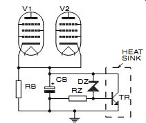
----- FIGURE 1: Floating tube bias.
===================
New Chips on the Block

AKM Semiconductor AK4112A
By Charles Hansen
AKM Semiconductor (www.akm.com) introduced the AK4112A, an S/PDIF or AES/EBU digital audio interface receiver (DIR) compliant with 24-bit, 96kHz data or non-PCM data stream such as AC-3.
Although conventional digital audio interface standards (IEC958 and others) for high-quality audio playback in DVD and home-theater systems are capable of transmitting multi-channel audio signals (AC-3/MPEG and others) while data is in compressed form, convention al DIRs are unable to differentiate be tween non-PCM and existing PCM data.
The AK4112A is able to cope not only with non-PCM audio data, but can detect compressed formats as well. Its low jitter clock recovery circuit, supported by a newly developed high-performance phase-locked-loop (PLL), delivers a master clock output that produces an optimal audio decoder front end for PCM data up to the DVD standard of 24-bit, 96kHz (24/96). A de-emphasis filter enables automatic de-emphasis of PCM data, reducing the complexity in digital signal processing (DSP) required for pre-emphasized signals.
The AK4112A has a channel selector that enables a 4-channel input suitable for current consumer-device applications as well as the direct input of un balanced signals to the built-in amplifier. The 3V or 3V3 power supply makes the AK4112A ideal for DSP interfacing and portable applications.
The AK4112A is compliant to consumer and professional audio standards, with performance suitable for interface with studio devices such as mixers or effects processors.
The $3.15 (10k) AK4112A uses a 28 pin VSOP package. Contact Richard Kulavik toll-free at 888-256-7364 for engineering samples.
======================
Music Corner: What Happened to the Magic?
By Don Monroe
I have a number of recordings of classical music that I particularly enjoy.
Some are the first recordings of the particular piece that I've heard, or renditions or interpretations that I know really well: works by Tchaikovsky, Rachmaninoff, Rimsky-Korsakov, George Gershwin, and a few other composers.
When I hear a different recording of these works, it sometimes sounds so different, I wonder if it's played from the same score. I'm referring to music with a lot of interplay between the various sections of the orchestra--e.g., the brass vs. the woodwinds. In the recordings with which I am familiar, this interplay between the various sections makes wonderful sense. But the new version sounds as though the various sections aren't even on the same page of the score.
The magic I am accustomed to hearing just isn't there. I don't know whether the conductor just doesn't know the score (not likely), or his vision of the piece is so different, or he is of a different school, or the recording engineer goofed up, or what. Or is it that I know the old recording so well, that any difference will sound wrong to me ? In the field of computing, it has been said that the text editor you learn to work with first will become the standard by which you measure all others.
You learn how to do things with the first editor that will define, for you, how those things should be done. You adopt a new editor only grudgingly.
The same with operating systems. If you start out on a Vax, and then must switch to a Unix platform, you do it with great reluctance, kicking and screaming all the way. This phenomenon probably happens in many different areas of life.
Maybe the same thing is happening when I listen to music. This could well be the case when one conductor plays a piece faster or slower than I am accustomed to. But I think I am talking about something more than differences in tempo. In the new recording, I just don't hear the music I heard before. Do others ever have that experience?
Reprinted, with permission, from The Arizona Audiophile, 5321 E. Elmwood St., Mesa, AZ 85205. Don may be reached by e-mail: dmonroe@amug.org.
The club sponsors a lively schedule of events and publishes an interesting and informative newsletter.
Don Monroe raises two interesting questions about listening which I have often thought about. First, does our first hearing of a particular piece imprint some kind of preference standard in our minds for how it should be performed ? Second, what are the variables that make performances seem so different to our interpreting minds ? I think these questions are of sufficient interest that we might have a worthwhile series of interchanges on them, perhaps as an ongoing feature in this magazine. After all, music listening is, at bottom, what this periodical is about.
I share Don's belief that somehow a first hearing of a particular performance can often set up a sort of musical yardstick for subsequent hearings. I always listen very care fully to the second movement of performances of Prokofiev's "Classical" symphony--a schoolboy exercise that launched his career. I first heard the St. Louis Symphony's performance of this work-on 78rpm disks. Very rarely does any subsequent performance of the second movement seem lyrically limpid enough to match my memory of something I heard in my 20s.
Harold Shoenberg wrote a wonderful commentary in the late, lamented Fi's pages about performance length. He ob served that contemporary style seems to dictate much slow er, more deliberate performances, comparing earlier and later renditions of Mahler in which certain symphonies were up to 17 minutes longer. Most of us who listen to classical music recordings are clearly aware that both the conductor and the orchestra make major differences in how a performance is executed.
Most experienced listeners develop preferences for certain favorite conductors-and sometimes a set of choices of a conductor or conductors for a specific composer. If you are able to compare six performances of Shostakovich's fifth symphony, I will wager that no two will be very much alike.
Fortunately, the willingness of some record companies to re-issue performances of early recordings offers a chance to compare some much older styles with those of the present day.
Given our common interest in music, it seems to me we could spare some space in this magazine for a conversation about our listening habits. I hope I am not opening a can of worms here, but the response to my invitation to share reader preferences for selections which test equipment performance, Test Tracks, has been very gratifying. In like manner, I hope many others will contribute.
If you have something to offer for what we will call "Music Corner," please feel welcome. I will ask you to keep your offerings to no more than 500-750 words--about two or three typed, double-spaced pages, please. Attachments to e-mail would be helpful, or clean typed pages that can be scanned. I look forward to hearing from you.
- E.T.D.
==================
Test Tracks
Reader-submitted selections to test audio systems
My seven favorite test CDs, by category, are as follows.
1. Electric Bass-Brian Bromberg, track 13 "My Bass," Nova Records 9351-2 ( Santa Monica, Calif.). Incredible bass playing and fidelity. This is a great test of inter-driver tonal balance and "voicing." There is a lot of depth and speed at the same time.
2. Deep Bass-The Organ Works of Cesar Franck Track 3, Disk 1, Dorian Recordings DOR-90135I ( Troy, N.Y.).
Track 3 is "Fantasy in A Major." Within the liner notes is a statement about not rolling off the bass anywhere in the recording chain. The 32' pipe comes through loud and clear on sub woofers that can accurately reproduce 16Hz. Since these "infrasonic sounds" are closer to pure tones than not, harmonics are not that rich.
Some lower-voiced recordings of instruments such as contrabassoon, bass drum, and so on are rather rich in harmonics and can easily fool the ear into thinking you are hearing the fundamentals. With the above-mentioned recording, this is not the case; if you don't have subwoofers that can provide adequate acoustic energy below 20Hz, the big pipes simply will not be heard (or rather "felt").
3. Piano-The Wonderful Sound of Three Blind Mice, Track 2 " Midnight Sugar," TBM CD-2530. Also available from Acoustic Sounds as JVC "XRCD"; " Midnight Sugar" is on CJVC 0023 and there is another: The Famous Sound of Three Blind Mice which is CJVC 0991. This is a Japanese CD that was often mentioned within the pages of Audio Magazine. I believe it is available from a distributor in Salina, Kans. (I no longer have the contact information). This is the most realistic-sounding piano recording I have ever heard (Audio always said the same thing, and they were right). The piano is reproduced with uncanny dynamics and authority; very clean and refreshing.
4. Female Voice-Nnenna Freelon, Track 6, "Future News Blues," Columbia, CK 48981 ( New York). Powerful, smooth voice; SSSSs and ZZZZs of many female voices and/or microphones are not present. Purposely having a tweeter level set too high will artificially raise the "S and Z" levels. If the speakers under evaluation appear to have this characteristic on this recording, it is my opinion that the tweeter level is either too high or has "peaking" in the high presence/low treble range. I also use this recording as a check of tonal balance between all drivers. Later in the track there is a very forward sounding sax part which is well record ed and also powerful yet well balanced throughout the range.
5. Violin-Midori, Live at Carnegie Hall, Track 10, "Tzigane," Maurice Ravel, Sony Classical SK 46742. The solo violin is very "wooden, natural and open." This piece does not sound strained or screechy like many violin recordings. To my ears, this is what a violin really sounds like at a live performance. This recording really brings out the subtle nuances of Midori's playing. Lesser speakers will show their weak ness(es), and better speakers will absolutely bloom when set up correctly.
6. Full Orchestra-Gustav Holst, The Planets, Chicago Symphony Orchestra and Chorus, James Levine. Deutsche Grammophon 429 730-2 ( Hamburg).
Track 1, "Mars, the Bringer of War." The opening measures have the strings playing "spicatto" (the bow lightly and repeatedly striking the strings rather than bowing). I have heard other recordings and performances of this same piece in which this effect is either muffled or to tally missing. This section should sound light and delicate yet still be obvious.
Later in this track the snare drum comes in; the sound of the drum is of equal intensity to the sound of the snare. Again, this is useful for determining the relative levels of the midrange and tweeter. (If only a two-way speaker, this is a good way to tell whether the upper range of the woofer really reach es into the "midrange.") The upper and lower brass sections are also very well recorded, as the overtones (harmonics) are all preserved in their proper proportions. This is a good test to determine whether there are any major peaks or dips in the "presence band."
7. Transient Response--Pink Floyd, Dark Side of the Moon, Track 3, "On the Run." This is the Mobile Fidelity Sound Lab "ULTRADISC" UDCD517 gold CD. The liner shows the original as Harvest Records/EMI. I'm not sure whether the original CD will have the same effect, as I only have the Ultra disc version.
This track has some very sharp clicks and ticks. The midrange and tweeter both must have extremely fast transient responses in order to appreciate this effect. The best setup on which I've ever heard this used an Eton 5¼” midbass and a Philips "Isophase Leaf" tweeter (ribbon). I used these ticks to time ad just the drivers.
With the arrival structure set correctly, these ticks and clicks just jump right out at you to some point in space well in front of the speaker box. This is a very uncanny phenomenon and defi nitely three-dimensional. Speakers not having these combined abilities will smear the signal, and maybe bad enough to be missed altogether.
Dan Martin; Greensboro, N.C.
Let's hear from you. Simply describe your seven favorite pieces (not to exceed 1000 words); include the names of the music, composer, manufacturer and manufacturer's number; and send to: "Test Tracks," [...]
---------------
Also see:
A QUICK BOOKSHELF PAIR: This author finds a way to satisfy his audio needs with a basic 5” driver-in a-box design.
NAD T550 DVD PLAYER: A versatile performer in the DVD field.