In the second part of this preamp project [also see: A
PHONO PRE-PREAMPLIFIER FOR THE CD ERA, PT. 1 ] , you'll
discover that paying close attention to good power-supply design and
construction techniques offers its own rewards.
by Norman E. Thagard, NASA Astronaut and DIYer
I have favored on-board regulation since my digital design days. however, my amplifier designs have had discrete regulators located on their own separate PC boards. This was partly because I used voltage-doubling techniques that added enough bulk to the doubler/regulator that it was not practical to place this circuitry on the preamplifier's PC board. Here, I returned to my roots with small IC regulators located on the preamp circuit board.

TRANSFORMER SELECTION
The current requirement for each pre amp channel is only 20mA/rail with an other few required by the monolithic voltage regulator. Thus, almost any transformer with sufficient secondary voltage should work. I had a 48V CT, 150mA transformer in my parts bin. I also purchased from Digi-Key a small 44V CT at 73mA toroidal transformer in case I decided to mount the power sup ply in the same enclosure as the pre amp.
In the end, I decided to take the conservative step of placing the power supply (Fig. 3) in its own enclosure with the unregulated DC output supplied to the preamp through a connecting cable. So, I used the old parts-bin transformer. If you wish two true monaural channels, I would recommend using two of the aforementioned toroids and duplicating everything. As for me, I opted for the dual mono configuration where the transformer secondary is the last common component with every thing downstream electrically and electronically separate.
A given power transformer can radiate at a level sufficient to induce hum in the preamp. [24] In theory, a toroidal transformer would restrict its field to the torus. Even so, it is probably better to locate the AC power portions of the system away from the signal portions. If that is undesirable or impractical, I recommend a small toroidal power transformer located as far from the preamp boards as possible.
This is more than a theoretical consideration, since the hum induced in this preamp when it was located immediately above the power amplifier's power transformer was intolerably loud. This occurred even though the prototype phono preamplifier is in a ferrous metal (steel) enclosure, and the power amplifier used two toroidal power transformers.
Electrostatic shielding with aluminum will clearly not prevent such hum induction. Simply locating the pre amp away from intense alternating magnetic fields is the most cost-effective solution. Moving the preamp just 6” away from the amplifier reduced the hum below the audible level.
FUSING
For the dual-mono configuration shown herein, the requirement from the power supply should be P_supply = 3.4W (two channels, 0.025A/channel, 48V RMS, v2 VDC/V RMS). This means a current draw from the power line of 3.4W/117V RMS = 29mA. I used a 63mA fuse for F1 in the prototype because I had one in the parts bin, but a 0.05A rating would be more conservative. I do not recommend using a fuse rated more than 0.1A.
If it blows, check for a wiring error or component failure before proceeding.
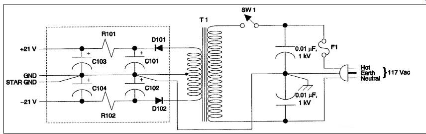
Figure 3: Power-supply schematic.
FILTER DESIGN
With such a small current requirement, it makes sense to try for additional ripple reduction by using two stages of filtering. This takes advantage of very large, but still very compact electrolytic capacitors, where the usual capacitor-input power-supply filter is followed by an RC low-pass filter.
My criterion for the capacitor values was the size of the capacitors in my parts bin. I had on hand four 2,200µF, 50V and four 4,700µF, 35V capacitors that were perfect for the same kind of Radio Shack prototyping boards that had served for the preamplifier channels. The former units are positioned as conventional capacitor-input filters, with one each in the positive and negative power supplies for each channel. Four 220 ohm resistors connect the four 2,200µF capacitors to the four 4,700µF capacitors.
In this way, each positive and negative power supply of each channel follows the raw DC output across the 2,200µF capacitors with an RC filter of 1.034s time constant. This corresponds to a filter cutoff frequency of (2pRC)-1 = 0.154Hz.
Capacitors of 470µF would be perfectly acceptable.
The total amount of ripple attenuation provided by the filter circuitry depends upon whether you use half- or full-wave rectification. I know that this is almost always full-wave in high-end equipment. However, the amount of ripple attenuation is so high that either type is acceptable in this application, and it may be that the 60Hz hum from residual ripple in a half-wave supply is less objectionable than any 120Hz hum from full-wave rectification. [25] The idea is, of course, that no audible hum be present no matter which rectification scheme you use. There is no audible hum produced by residual ripple in this preamp with the power supply described here, a supply that uses half wave rectifiers.
Since ripple is attenuated by a factor of ten (20dB) for each decade that the ripple frequency lies above the filter cutoff frequency, the second stage of filtering here provides 20dB/decade × 2.6 decades = 52dB of additional reduction where:
60Hz/0.154Hz = 390 number of decades = x, where 10x = 390; log 10x = x = log 390 ? 2.6
I based the selection of 220 ohm as the value in this application on a good com fort level that the unregulated, but heavily filtered output voltage delivered to the preamplifier circuit board would be no less than about 18V under worst-case conditions. The reason for that criterion will become evident. The above relation ships show that if you select the full wave rectifier, you will obtain 6dB more ripple attenuation from the RC filter.
RIPPLE BLIPS
The ripple on an oscilloscope at 2mV/division is barely visible, appearing al most as a pulse train of small "blips." The blips are probably due to the heavy current flow during the short period in which charging current flows through the rectifier diodes to the 2,200µF capacitors of the capacitor-input filter.
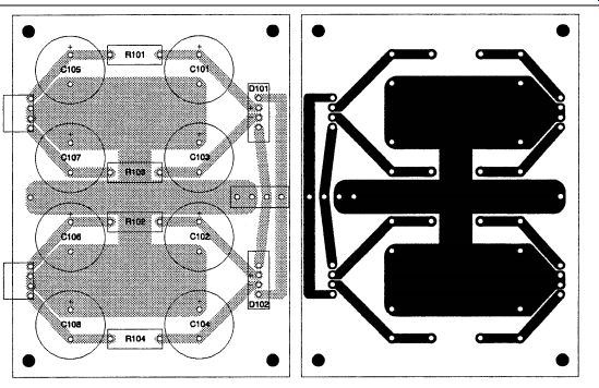
Figure 4: Power-supply board parts placement (left) and PCB pattern
(right).
A small resistor between the diodes and the capacitors would reduce the amplitude of the blips, but there is already a heavy overkill situation here.
As a matter of interest, if ripple were to be reduced to 10mV with a capacitor input filter alone, the charging current through the rectifier diode would be about 5A, even though load current is a mere 25mA. Charge is the product of current and time. The charge removed from the filter capacitor during the 16.7ms cycle time T (T = 8.3ms in a full-wave rectified supply) must be restored to the capacitor during the short (in a well-designed supply) recharge period, delta t.
If recharge (diode) current is considered constant (it is not, but the approximate answer so obtained is sufficient), then
ILOAD × T = IRECHARGE × delta t.
Solving this expression for charging current yields IRECHARGE = (T/ delta t) × ILOAD.
This formula already suggests that charging current will be much greater than load current because the small charging interval delta t is so short in comparison to the relatively long cycle period T. [26] Although diode conduction actually continues past the peak capacitor volt age Vpeak, if you assume that conduction begins at time ?t before it ceases at Vpeak, then voltage magnitude at the onset of conduction is Vpeakcos ??t. The quantity ??t is the diode conduction angle, and for a half-wave rectifier the ripple frequency is ? = 377 s-1. The peak to-peak ripple voltage is therefore Vripple = Vpeak - Vpeakcos ??t.
Remember that ??t is intentionally made small to reduce ripple so that the trigonometric approximation cos ??t ? 1 - ½( ??t)2 is valid. If the output voltage of the supply is to be about 21V, then you can solve for delta t ? [2Vripple/Vpeak] ½/ ? = [2(0.01)/21]½/377 ? 82µs
From this, it follows immediately that IRECHARGE ? (0.0167/0.000082)(.025A) = 5.09A, a pretty impressive number.
ILOAD is constant at about 25mA, and the capacitor discharges for almost the entire 16.7ms period T. The formula for the discharge of a capacitor at a constant current leads to Vripple ? ILOADT/C.
For the 2,200µF filter capacitors, then, Vripple ? (0.025)(0.0167)/(0.0022) ? 0.189V. Surge current through the diode in the preamp power supply is on the order of 1.2A, which is still a pretty startling number, but the surge ratings on even small rectifier diodes are well in excess of this. For example, a 1N4002 diode has a 30A surge rating, but is sold as a 1A rectifier. It should be clear why surge ratings need to be so much higher than the average DC load-current rating.
A capacitor of almost 42,000µF would be required to reduce the ripple to 10mV. Using the additional RC filter reduces the almost 200mV ripple to less than ½mV with far smaller capacitors.
It is enlightening, even eye opening, to look at things like this. Many designers treat power supply design very casually. I used to, too, until it bit me.
VOLTAGE REGULATORS
Unregulated output voltage from the rectifier-filter will vary, depending upon the power transformer secondary volt age under load. Measured voltage was 24V at a current draw of 25mA with the particular transformer that I used. Once you've selected the actual transformer, you could simply increase the resistor value in the RC filter or, better, add yet another stage of RC filter so that approximately 15V would be presented to the preamplifier under load. In either case, it would require no voltage regulator.
While you are certainly free to use other schemes, the one chosen here was to use 78L15 and 79L15 IC voltage regulators on the preamplifier circuit boards to supply the needed ±15V power rails.
These voltages were limited to a 15V magnitude because of the 30V drain-to source voltage limitation of the 2SJ109 JFETs. Some features of on-card regulation are discussed in National Semiconductor's Voltage Regulator Handbook. [27] This publication is a good general reference for power-supply design.
As always, there are constraints you must consider. If the unregulated volt age is too high, the voltage and/or power-dissipation limits of the regulators will be exceeded. If this voltage is too low, then the regulator will "drop out," that is, it will cease to regulate be cause some active device within it is no longer in its active operating region.
Although these limitations are slightly different for the 78L15 and 79L15 regulators, the worst-case limits require an unregulated voltage magnitude in the range 17.5V = Vin-unreg = 28V. These regulators are widely available from sever al manufacturers, including the re placement series manufacturers such as ECG, NTE, and RCA. Therefore, since parts numbers will vary, be careful to select regulators whose output-voltage tolerances are guaranteed to be within ±5%. There are even tighter-tolerance devices available if you wish to go to the trouble and expense of finding them, but it really isn't necessary to do so.
Each regulator will, for stability, re quire the input capacitor shown, unless you place the regulator immediately at the output of the unregulated supply.
With the recommended value for the 79L15's input capacitor, there was an intermittent, low-amplitude, high-frequency oscillation. This I tamed by in creasing the capacitor value to 1µF. For consistency, I also used 1µF input capacitors for the 78L15 regulators.
A case could be made for deriving first-stage supplies from the output of the 78L15/79L15 regulators by using yet another RC filter, or perhaps a zener.
This would mean that the first stage would operate at some lower voltage.
This should be no problem, however, given that the output swing demanded from the first stage is significantly less than that required from the second.
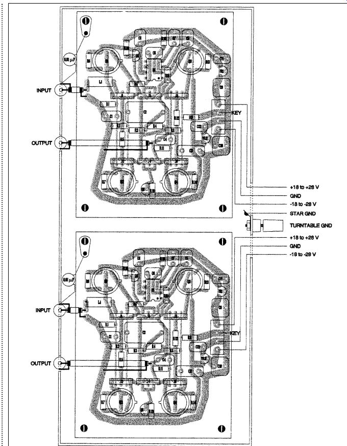
Figure 5. Preamp-enclosure construction pictorial.
CONSTRUCTION
The layout and construction details are reasonably well described in Figs. 5 and 6. Nonetheless, I should elaborate on a few of the details.
Pay attention to the connection of the three-wire AC power cord. There is potential danger if it is not wired as shown.
For the two-phase, 117V AC house line, the color convention for wiring, including the AC line cord, is green = ground, white = neutral, and black = hot.
[28] As a designer, I always think about the possibility of modification or repair of the device, especially for the proto type version. For that reason, I liberally employ quick-disconnects (QDs) as well as transistor and IC sockets. The JFETs are not socketed here because of their unusual pinout. The power cable between power supply and preamplifier enclosure has QDs at both ends. If you use QDs on this cable, be sure that it has male connectors at the power-supply end and female connectors at the preamp end. Thus, even if you use Molex header-type connectors, the "hot" connector pins are not exposed. I have serious reservations about claims of sonic effects of QD metals. Even so, I favor gold connectors because of past experience with other types' reliability problems due to corrosion.
I mounted chassis-mount RCA jacks to the edge of the PC board, and used uninsulated wire to both strap and ground the sleeve (outer portion) of each jack to the board, with the mating portion of the jacks extending out be yond the board's edge. This arrangement allows unimpeded connection to the jack of the RCA plug from the tone arm. I soldered a 0.01µF disc ceramic capacitor to the ground trace immediately adjacent to the ground trace connection of the input jack, and soldered the other end of the capacitor to a solder lug, which, in turn, I grounded to the chassis via the screw attaching the PC board to the nearby metal standoff.
A standoff under each corner of the board provides its secure mounting to the chassis while ensuring that the bottom of the board does not contact the chassis. All four standoffs should obviously be of the same height. You can make them either of metal or insulating material, except that, as described earlier, the one to which the solder lug is attached must be made of conducting material.
I made the connection between the inner-conductor (center) connector lug of the input jack and the board trace to inductor L1 with a very short piece of uninsulated wire, since the jack was mounted immediately adjacent to L1. I similarly strapped and grounded the output RCA jack at the board's edge, but made the connection between its inner conductor connector lug and the appropriate board trace with small-gauge shielded cable because of the distance involved. The shield of this cable is grounded only at the phono-jack end.
With this mounting arrangement of the jacks, it was necessary to drill holes only in the front panel of the preamp en closure, allowing the RCA jacks to protrude almost completely outside the en closure. To do this, the front edge of the PC board must contact the inner side of the front panel of the enclosure. The front-panel holes for the jacks must be sufficiently large that neither the jack nor the shield connector portion of any connected RCA plug contacts the front panel. Also be sure that no other PC board component or trace contacts the front panel. This should not be a problem with the PC-board pattern provided.
You could achieve the same effect more easily by using PC-mount RCA jacks, but I had none in my parts bin, and so devised the scheme just de scribed. If you use PC-mount jacks, you must modify the board's trace pattern accordingly.
GROUNDING
Some attention to the grounding scheme is required. For one thing, there are differences among various turntables, tonearms, and even cartridges in the way grounding is handled. For that reason, the actual inter connections may be different, depending upon the builder's specific system and its components. It will probably be true that most builders will be very familiar with the schemes that work best in their systems.
I emphasize again that the RCA input and output connectors are insulated from the enclosure. It is important that the input connectors be grounded to chassis only through the 10n capacitors as shown. While I understand that isolating the input connector ground from the chassis avoids a ground loop, I have never seen a reason given for the capacitors. I assume they are for RF by pass, given the small capacitance value.
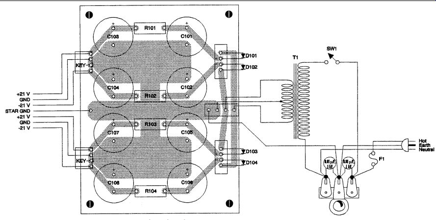
Figure 6: Power-supply-enclosure construction pictorial.
These capacitors may be disc-ceramic types. Voltage rating is probably not critical, but since 10n, 1kV disc-ceramic capacitors are used as AC-line filters for the power supply, it is convenient to make all of these capacitors the same and perhaps save on quantity purchases.
A ground loop can occur anyway if the cartridge or tonearm cable connects both channel grounds at the turntable end. If a continuity check indicates this situation, then break the potential loop by opening the shield connection at the turntable end for one channel only. [29] If that is not possible, you can try omitting one shield connection to the PC board at the preamplifier end for one channel only.
I am not sure whether this, of itself, will give satisfactory results, because signal ground for that channel then comes circuitously from the other channel to the power supply and back to the first channel. I have seen amplifiers oscillate with such circuitous ground paths. As an alternative, after breaking one shield connection for the PC-board RCA input jack, connect the ground trace of both channels' PC boards together and break the ground return to the power supply for one channel only.
Some turntable/tonearm combinations offer an optional ground lead for connection to the preamplifier chassis. Accommodation of this option is the reason for the binding post labeled "TURNTABLE GND" on Fig. 5. The decision whether or not to connect this optional ground lead is based empirically on the situation that results in the least hum.
For my system, the SME 3009 tone arm cable provides this optional ground lead, which, at the tonearm end, is connected to the turntable platform of a Thorens TD 125. Connection of the optional ground to the preamplifier binding post is the preferred configuration in my case, since this reduces hum below the audible level.
At the power supply, only one chassis interconnection point should exist.
This is nicely illustrated in Fig. 6, which also indicates what is meant by such terms as "STAR GND." LAYOUT Some of the layout considerations have already been mentioned: for example, the importance of keeping the power transformer and other possible sources of hum induction as far away from the preamp boards as possible. Otherwise, the layout is not very critical.
If you use my PC-board patterns, much of the layout is predetermined.
The power-supply rectifier diode pat terns marked D101 and D102 are for the particular monolithic full-wave diode package used. The pattern will accommodate discrete diodes of the 1N4002 type. Just connect the anode of one diode to the point marked "-" and the cathode of the second diode to the point marked "+." You should place the other ends of the two diodes in the adjacent unmarked AC input points. This is shown in Fig. 6. For the placement of any other components not specified in the parts list (Table 2), my assumption is that if you are smart enough to select an appropriate substitute, you are smart enough to determine its proper placement.
SETUP AND ADJUSTMENT
No adjustments are required. It is a good idea, as mentioned in the text, to verify the differential amplifier currents by measuring the voltage across current source resistors R5 and R12. Unless you used severely mismatched BJTs in the current mirrors, cascode current should be OK.
I always check the power-supply volt ages before I connect the rails to the circuit. I also use current-limited bench power supplies for breadboard work, and a Variac for initial power up and checkout of the prototype version of a new design or after repairs. The presence of the 220 ohm resistors in the power supply affords short-term protection against short circuits downstream, but in the long term, their resulting power dissipation would exceed their power rating. The IC voltage regulators are internally protected against short circuits.
CONCLUSION
I think that this pretty well covers the whys and wherefores of this project. It is a satisfying approach from the stand point of precision in a relatively simple discrete design. The THD was only about 0.006% up to several kHz, rising to 0.026% at 20kHz with a 0.5V RMS output.
Obviously, it is possible to achieve significantly lower levels of THD with higher open-loop gain and therefore more feedback. It is difficult to do so, however, with the precise active-passive equalization scheme realized through just two one-stage op amps as I did here. The proponents of "less is better," and especially those skeptical of the benefits of negative feedback, will appreciate this trade-off.
As for listening attributes, the sound is open and dynamic. You hear no stridency, even on massed strings. The bass is awesome, and I have no explanation for this. I do not know about the Adcom or Marantz preamps, but otherwise it is true that there are no coupling capacitors in the signal path, even at the input of the power amplifier currently in my system. This was possible because the servo limited DC offset at around 600µV. Still, there should be no perceptible difference in bass, even with coupling capacitors, as long as the low-frequency cutoff is well below the lower limit of hearing.
It is simply amazing how good many recordings were in the days of vinyl. The ambience in the few Mercury Living Presence records that I have is remarkable. I am skeptical of many "golden ear" claims of magical qualities of amplifiers and preamplifiers and I attribute none to this design. I simply assert that this phono preamp is good enough to accurately reproduce the information that is in the recording medium.
I believe you will thoroughly enjoy its use, provided that other components in the stereo system are equally good.
-----------

TABLE 2:
PARTS LIST, POWER SUPPLY
RESISTORS R101, R102 220 ohm, 2W, 2% metal
CAPACITORS C101, C102 2,200µF, 50V aluminum electrolytic C103, C104 4,700µF, 35V aluminum electrolytic
TRANSFORMER T1 48Vct at 150mA (see text)
FUSE F1 0.05A (see text)
-----------
Happily, I continue to be impressed with the sound even after several weeks. The more usual case is to be very impressed initially, with the enthusiasm fading after the first few listenings.
I am listening at higher volume levels than before. This may be a sign of lower apparent distortion, since there is a tendency to adjust volume to a level just below that at which distortion be gins to be objectionable. Finally, it's impossible to overstate the enjoyment de rived from "rolling your own."
REFERENCES
24. Manny Horowitz, How to Build Solid-State Audio Circuits, Tab Books/No. 606, 1972, (pp. 311-12).
25. Manny Horowitz, How to Build Solid-State Audio Circuits, Tab Books/No. 606, 1972, (p. 297).
26. Mark N. Horenstein, Microelectronic Circuits and Devices, Second Edition, Prentice Hall, 1996, (Problem 4.79, p. 225).
27. Voltage Regulator Handbook, National Semiconductor Corporation, 1975, (p. 1-1).
28. The ARRL Handbook for Radio Amateurs, The American Radio Relay League, 1997, (p. 11.24).
29. Manny Horowitz, How to Build Solid-State Audio Circuits, Tab Books/No. 606, 1972, (pp. 314-15).
Also see:
A PHONO PRE-PREAMPLIFIER FOR THE CD ERA, PT. 1
PRODUCT REVIEW: BUDGET PHONO PREAMPS---Here's a survey of some low-cost phono preamps. Find out which one is right for you. [Apr. 2003]