MORE ON TL SPEAKER DESIGN: This author's update on his two-way transmission-line design includes a modified crossover, along with measured responses and a revised simulation.
----------------------
Here's an update to the article "Another Look at TL Design" (SB 3/99), in which the author described a two-way system featuring TL designs for both bass and treble speakers.
By John Mattern
In my original article, the bass unit covered the bass and midrange, while the treble unit covered the midrange and high frequencies.
The treble unit was originally a cone type with a wizzer, but I replaced it with a coaxial speaker of the same size. The 3½” coaxial speaker does not require external crossover components and therefore has little impact on the electrical diagram.
Because of my wish to use a simple 6dB crossover, I needed a very large overlap of the bass and treble drivers in the midrange. The new treble unit in its TL enclosure responds down to 128Hz, providing more than three octaves of overlap below the 1.5kHz crossover, while the bass speaker provides roughly two octaves above the crossover. This bass-speaker design was based on a computer simulation that resulted in a highly satisfactory unit.
A newly revised computer simulation uses Olson's1 finite conical horn equation (modified to include losses) rather than Ramo and Whinnery's [2] general electrical transmission-line equation to calculate the load at the throat of the horn. Both approaches gave virtually the same result. Another change to the simulation involved a new model for the velocity of sound that accounts for the dependency of velocity on frequency. I will discuss these changes in more detail later.
BASS-UNIT CHANGES
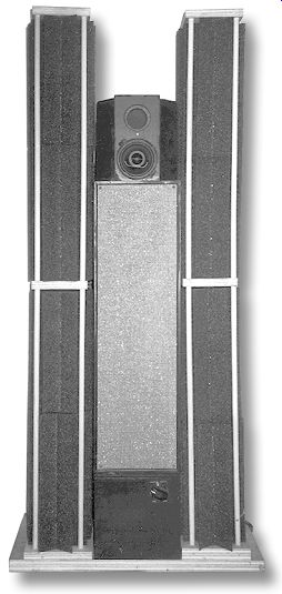
The bass unit received a coat of semi gloss black and a full-length grille with narrow black trim on the edges (Photo 1). A speaker stand containing a redesigned crossover provided additional height to place the treble unit at ear level. I built a second complete system except that the bass driver I used was of necessity the Audax woven-carbon-fiber HM130C0 that re places the discontinued HM130X0.
Frequency-response measurements showed no significant differences be tween the two systems.
TREBLE-UNIT CHANGES
Changes to the treble unit are shown in the mechanical drawing of Fig. 1. I cut a 3” port opening to extend the bottom end of the treble unit's response, but this resulted in a sizable dip at 512Hz.
When I reduced the opening to 1.75 ohm, the dip was more reasonable. To do this, I inserted a hardboard washer with a 3” outer diameter and a 1.75” inner diameter into the 3” port. The dip was apparently caused by out-of-phase sound from the port. I also reduced the amount of fiberglass stuffing, which now has a 2”× 3” cross section instead of the original 3”× 3”.
I also changed the driver to a Boston Acoustics 3.5” coaxial driver that has a more extended high end. I can't hear it anyway (11kHz is my current limit). The box was turned on its end with the driver down, and I added side blocks with 45° corners to reduce the diffraction effects above the step frequency. Measurements showed only a slight improvement, suggesting that the fluctuations are largely dependent on the driver design rather than on the enclosure.
Fortunately, no life-threatening modifications of the treble box were needed, which was not true in the case of the crossover. I painted the treble box to match the repainted bass box.
CROSSOVER CHANGES
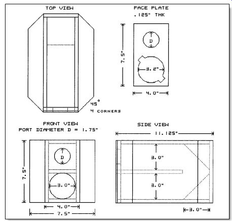
FIGURE 1: Modified treble enclosure.
The new speaker stand with an internal crossover is shown in the mechanical drawing of Fig. 2. I located the capacitors and resistors on a PC board I attached to the inside top of the stand (Photo 2). I placed the inductors and Lpad on the inner side walls of the stand. The circuit schematic of the speaker system is shown in Fig. 3, and the parts list is in Table 1. The speaker stand brings the treble unit to the correct height for listening when seated.
PHOTO 1: The revised left channel complete with absorbers. The treble unit is placed vertically and is flanked by 1.75” thick blocks with 45° ends.
I added the parallel combination L1 and R3 to correct the bass-unit diffraction step. The original high-pass filter had two paralleled 8.2mF capacitors that I replaced with a single 33mF one to adjust the diffraction step for the treble speaker. Note that the L-pad setting must be reduced to complete the correction. Since the new driver is a 4 ohm unit, I placed a 4 ohm resistor in series with it.
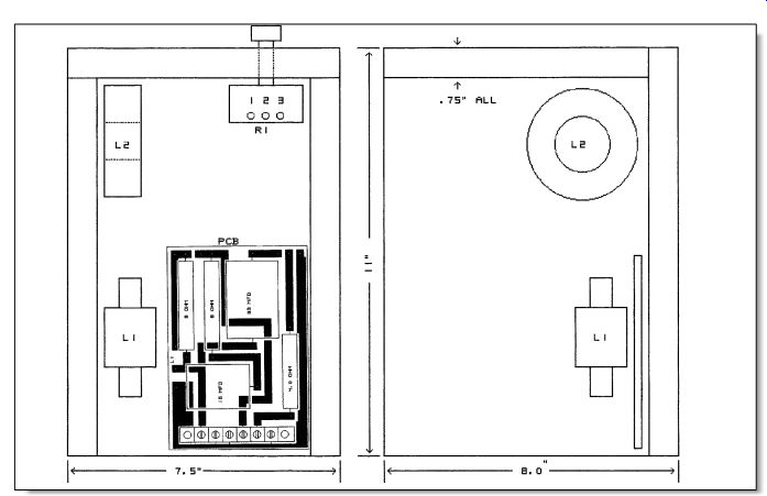
FIGURE 2: Bottom and side views of crossover inside speaker stand. (The stand's right leg is omitted in the side view.)
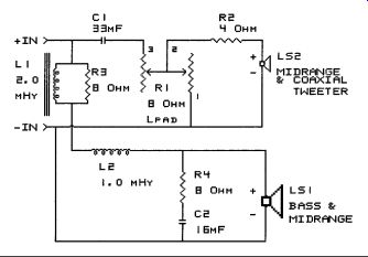
FIGURE 3: Speaker-system electrical schematic.
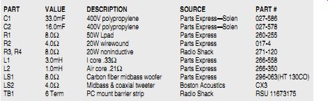
TABLE 1 SPEAKER SYSTEM ELECTRICAL PARTS LIST
---------------
PART VALUE - DESCRIPTION - SOURCE - PART #
C1 33.0mF 400V polypropylene Parts Express-Solen 027-586 C2 16.0mF 400V polypropylene Parts Express-Solen 027-578 R1 8.0 ohm 50W L-pad Parts Express 260-255 R2 4.0 ohm 20W wirewound Parts Express 017-4 R3, R4 8.0 ohm 20W noninductive Radio Shack 271-120 L1 3.0mH I core .33 ? Parts Express 266-558 L2 1.0mH Air core .21 ?
Parts Express 266-350 LS1 8.0 ohm Carbon fiber midbass woofer Parts Express 296-063(HT 130CO) LS2 4.0 ? Midbass & coaxial tweeter Boston Acoustics CX3 TB1 6 Term PC mount barrier strip
Radio Shack RSU 11673175
-----------------
BASS-UNIT DIFFRACTION STEP
The near-field frequency response for the bass unit is shown in Fig. 4 for the system with the HM130XO drivers. The top curve shows the near-field response of the bass with a diffraction step taking place between 256 and 512Hz.
At first I used the receiver's tone control to balance the output from the bass unit. However, I soon resolved to correct this external acoustic problem in the crossover rather than in the amplifier. The approach I used was suggested by Ralph Gonzalez and reported by Weems. [3] Gonzalez's solution to increasing bass response for a single speaker with only one voice-coil winding puts an inductor shunted by a resistance equal to the speaker impedance in series with the bass driver.
The values I used were based on the data in Fig. 4. I added a 3.0mH inductor, L1, with a 8 ohm parallel resistor, R3, in series with the bass speaker. This centers a 6dB downward step over the upward diffraction step with the results shown in the lower curve of Fig. 4. Note that when the L1 and R3 are placed in series with L2, the correct value of L1 becomes 1.8mH.
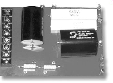
PHOTO 2: Component side of crossover board showing resistors, capacitors, and posts for connections to external components. (The series-connected resistors are a substitute for the specific parts, which were out of stock.)
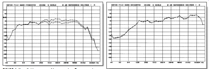
FIGURE 4: Near-field response of bass speaker. Top curve shows diffraction step starting near 250Hz. Bottom curve shows response with RL circuit in series with speaker.
FIGURE 5: Near-field response of treble speaker with and without side pieces.
The 3.0mH Parts Express inductor specified in Table 1 is satisfactory, but puts the total resistance in series with the speaker a little on the high side, so I tried winding my own inductors. I wound several with iron cores, trying both I and H cores. Each used many large laminations, which I obtained by scavenging two heavy-filter chokes.
Because of the known problems with harmonics, I used an RLC bridge to evaluate the distortion. The I core's un balanced harmonic residue was better than 60dB down, while the H-core inductor was only about 50dB down. The respective resistances were .4 and .25 ohm.
I am currently using the I-core inductors. A computer plot of the low-pass CO branch using a diffraction-step model based on Olson's data for a spherical baffle showed the optimum value for L1 to be 1.8mH. The model is quite accurate for a spherical baffle, but will not model the fluctuation at frequencies just above the step in the case of an angular baffle.
TREBLE-UNIT DIFFRACTION-STEP CORRECTION
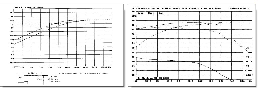
FIGURE 6: High-pass filter diagram and response with diffraction correction.
FIGURE 7: Simulation of TL speaker using alternate software.
In the case of the treble unit, I used a different approach because of the high impedance of the treble branch of the crossover. The approach I chose used the diffraction step as part of the treble unit rolloff, which meant using the center of the step as the design crossover and locating the LF corner frequency an octave below what it would normally be. The new crossover is shown in the speaker-system diagram (Fig. 3). Figure 5 shows that the diffraction step occurs between 1 and 2kHz, at approximately 1.5kHz. I have used 1.5k as the center frequency in Fig. 6 to determine the value of capacitor C1.
The diffraction-step response (top curve of Fig. 6) was plotted from a model based on Olson's data4. The center curve is the filter response of a single-pole high-pass stage taken alone, while the bottom curve is the effective response when the dB values of the two curves are added. The corner frequency of the high-pass filter was adjusted until the 3dB point of the sum curve was at 1.5kHz. Listening tests confirmed that this was a reasonable approach. Of course, that does not deal with the fluctuations that occur above the step frequency. This would require that the treble enclosure be an isolated sphere.
The latest treble enclosure is a compromise in that direction.
CHANGES TO THE SIMULATION SOFTWARE
I would like to report that my measured response of the bass unit agreed with the simulated response, but this is not the case. A comparison of my measured response with my simulated response shows a significant discrepancy below 38Hz. A possible cause is the approximation used in modeling the horn taper.
Olson's equations [1] for the cylindrical and conical horns do not provide for losses, so instead I used the electrical transmission-line equation given by Ramo and Whinnery. [2] They give two forms of this equation: an ideal form that does not provide for losses, and a general form that does. Their ideal equation is mathematically identical to Olson's cylindrical horn equation, so I was reasonably safe in using their general equation that includes losses. I accounted for the taper by treating the line as a quarter-wave transformer whose throat-to-port area ratio determined a velocity correction to the un-tapered line. I believe the result to be valid as long as the line length is a quarter wavelength or longer.
The new simulation software (Fig. 7) uses Olson's equation 1 for the throat impedance of a finite conical horn in stead of the equation for a finite cylindrical horn. This also is an ideal equation for a horn without losses. Expanding the equation revealed the terms that should be lossy. These I replaced with appropriate hyperbolic trig functions that contain both phase and loss information.
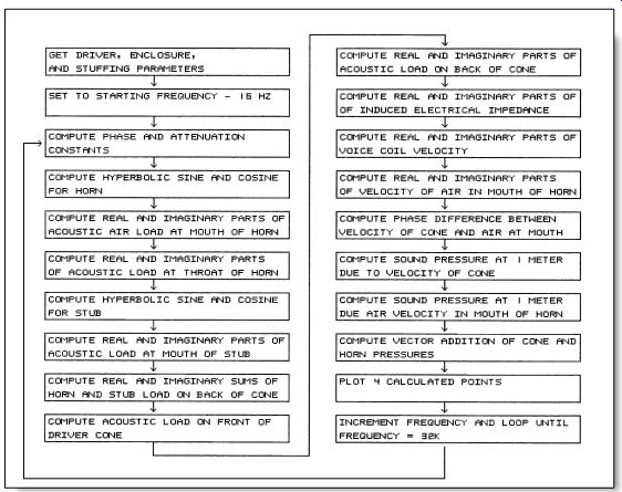
FIGURE 8: Simulation-program flowchart.
When this awful mess was included in the software program, the bottom end dropped off slightly faster than with the previous approximation, but there were no startling differences. In this case, no velocity correction for the area ratios was required. I have included a program flowchart (Fig. 8) for the sake of completeness.
CONCLUSION
My simulation calculations are based on an assumption that both the driver cone and the horn's mouth are flush with a large baffle. Neither of these assumptions is fully satisfied in the present design. The assumption is satisfied at the high end of the spectrum, but not at the low end, where the cone and port radiate both forward and backward due to diffraction around the enclosure.
Here it causes a 6dB loss. The changes to the crossover deal with the step, but not the fluctuations that accompany it.
Those require a rounded enclosure without sharp edges.
I must comment on the discrepancy between the simulated and the measured low-frequency rolloff. The simulation in Fig. 7 shows a gradual fall-off below 38Hz, while the measured response fell off rapidly below 38Hz. The rapid drop in the real speaker could be caused by air leaks. An obvious case in system #1 is the leakage path between the voice coil and the pole piece. The Audax drivers used in system #2 lacked the phase plug, having instead a cap over the voice-coil former, thus closing off this leakage path. However, system #2 had virtually the same low-end response as system #1, even though there was no leakage path around the voice coil! Of course, the microphone will con tribute to the measured fall-off. I have been using the same Panasonic electret element as does the Mitey Mike for my frequency-response measurements.
I have several of these inexpensive elements from Radio Shack, and they all give the same result when used with the Radio Shack digital multimeter and my NEC portable computer. I re placed the 0.47mF coupling capacitor in the battery pack with a 10mF tantalum capacitor. My mike amplifier is very wide-band.
I would like to point out that it is not unreasonable to achieve high levels of power from the horn. Predicted and measured pressure on the backside of the cone at low frequencies far exceeds the pressure on the front side when the line's cross section is equal to the cone area. I chose this area because Bailey5 reported that smaller areas were undesirable.
The simulated frequency-response curve of Fig. 6 shows a dip in the simulated response at 180Hz, which I believe is the result of cancellation by out of-phase radiation from the port. When the measured attenuation in a straight transmission line is used in the simulation, the predicted dip is larger than the measured one. This suggests that the attenuation in the folded horn is in creased at the higher frequencies by its four bends. Accordingly, I have in creased the attenuation coefficient in the simulation plot of Fig. 7 by 3dB at 180Hz to equalize the two dips.
I am surprised by the large change in velocity of sound with frequency caused by movement of the fiberglass tangle. The rapid drop of velocity with frequency appears to hold the phase difference at the port to less than 90° down to very low frequencies. This seems to me an advantage.
Even if you assign all the discrepancy to the simulation model, it is still reasonable to consider the bass-unit de sign a success. However, I will continue to seek an explanation for the differences. Also, the new crossover is probably close to optimum for the design approach I chose. I am not quite satisfied with the treble-unit enclosure, and will probably try a rounded enclosure next.
As it now stands, the sound is balanced, very clean, and natural. The last two adjectives are not mine. These changes to my TL speakers have resolved some but not all of my questions.
REFERENCES
1. Olson, H.F., Elements of Acoustical Engineering, D. Van Nostrand Company, Inc., pp. 102-103, 1947.
2. Ramo and Whinnery, Fields and Waves in Modern Radio, John Wiley and Sons, p. 47, 1947.
3. Weems D. B., Great Sound Stereo Speaker Manual, Tab Books, p. 181, 1990.
4. Olson, H.F., op. cit., p. 20.
5. Bailey A. R., "A Non-resonant Loudspeaker Enclosure Design," Wireless World, p. 486, October 1965.
----------------------
Also see:
B&W DM602 S2 SPEAKERS: A look at an affordable two-way from the company that gave us the unique Nautilus speaker.
ON ANGELS' WINGS, PT. 2: With the preliminaries out of the way, it's time to assemble this ribbon speaker and--the moment you've been waiting for--kick back and take a listen.