A Study of Amplifier Harmonic Distortion Spectrum Analysis
The work of this noted audio authority on objective measurements is still relative after 25 years.
By Jean Hiraga
Modern amplifier designs are nowadays capable of very low measured harmonic distortion, on the order of 0.005% or even 0.0005%; levels which can only be measured with elaborate test instruments such as the Radford Series 3 and those from Sound Technology (USA). Despite this state of affairs it is interesting that valve amplifiers, which often have a distortion level at least 100 times greater (e.g., 0.5%) may sound subjectively no more, and can sound a lot less, distorted than transistor designs in spite of the higher measured level. This causes endless de bates between the "golden eared" listener and the engineer tone quoting the position of the distortion meter needle; the other talking about the special tone of piano x of year y.
This article does not intend to discuss in detail the relationship between a particular electronic circuit design and its subjective result, as this is far too large an undertaking. However, some particular measurements have been made which may help to reconcile the engineers and the listeners. This is not simply a question of taking certain measurements or conducting blind listening tests on amplifiers, but an at tempt to show that a particular measurement may result in an indication of the ability of an amplifier to reproduce a musical sound.
---------------
Hi-Fi News & Record Review, March 1977.
---------------
Figure 1 and Table 1 show the spectral composition of a violin note with its various harmonics and their relative levels. It is important to note that the tonal color or "personality" of the violin lies in the high-order harmonics from the 4th to the 20th, whose levels are extremely low compared with the second or the third. The slightest modification of the relative levels of these harmonics will change the spectrum of the signal fed to the loudspeakers and hence the tonal "color" of the violin, making a Stradivarius sound like a very cheap violin, for example.
This spectrum analysis technique can also be applied to audio amplifiers, but as yet few people have been interested enough to analyze the actual con tent of the measured distortion (whether 0.5% or 0.0005%). However, the particular pattern of harmonic distortion in an amplifier is extremely significant and can provide important indications of its subjective qualities; it is not necessarily wrong to refer to "musicality of distortion."
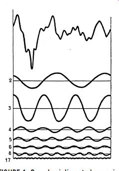
FIGURE 1: Sample violin note harmonics and relative levels.
----------

TABLE 1
FREQUENCIES(HZ) HARMONIC RANGE % OF TOTAL ENERGY LEVEL (In dB) 198 1 0.1 0 392 2 26.0 24.2 588 3 45.2 26.6 784 4 8.8 19.5 980 5 8.5 19.3 1176 6 4.5 16.5 1372 7 0.1 1.3 1568 8 4.8 16.8 1764 9 0.1 0.6 1960 10 0.0 2156 11 0.1 1.3 2352 12 0.0 2548 13 0.2 2.4 2744 14 0.0 2940 15 0.1 3136 16 0.0 3332 17 1.1 10.4 3528 18 0.1 3724 19 0.2 2.6 2920 20 0.0 Total = 99.9
-----------
It has been possible to make these measurements by using very elaborate test equipment made by General Radio (USA). These instruments are very expensive and are only available in two places in Japan (where these tests were undertaken): the National Research Laboratory and the Kanno Research Laboratory. Kanno specializes in valve amplifiers and audio transformers and has also been responsible for measurements concerning the "Hikari Bullet" express train. These tests give a very ac curate measurement of the harmonic distortion by means of a graph which shows the relative level of each individual harmonic.
A fundamental of 200Hz was used in stead of the more conventional 1kHz for various reasons, particularly in order to represent the human voice. Six transistor amplifiers were tested (most ly of Japanese origin), and five valve amplifiers, many of which were crafts man-made. The measurements were made at a power rating of 3W to simulate average listening conditions.
Olson has shown that the reproduction of a pure frequency is not musical and that it is necessary to add very regularly reduced harmonics in order to produce a sound which is subjectively musical. It is pertinent to make an analogy to the difference in taste between distilled water and " Vichy" water, where the latter is invariably preferred. Even though the distortion in an amplifier may be at extremely low levels, the content of this distortion must conform to the laws of harmonic levels in order to give subjectively musical reproduction.
It is also relevant to point out that most amplifiers use the classic push/pull circuit which reduces the even harmonics. However, it is known that these even harmonics are less audibly objectionable than odd harmonics, and to reduce only these confers no real advantage. The use of high levels of feedback is also not recommended, as this masks rather than suppresses distortion. In transistor amplifiers, this may result in the production of high order harmonics, which is catastrophic when considering the case of the afore mentioned violin. I would like to point out that amplifier designers are able to design amplifiers with both low distortion and feedback, Mr. Kaneda (Japan), Mr. Radford (England), and Mr. Vaissaire (France) being notable examples.
THE TRANSISTOR AMPLIFIERS
a)The spectrum of amplifier 1 shows the presence of unwanted harmonics at 300, 700, and 1,300Hz. Despite the low distortion level, subjectively you find a lack of upper bass and a slightly raised treble which is lacking in purity.
b) Amplifier 2: Note the absence of harmonics beyond the third, due per haps to the high level of feedback.
Subjectively there is a feeling of a lack of lower treble, and a flat sound which gives the impression of a lack of depth, although the higher frequencies are well defined.
c) Amplifier 3 is a zero feedback design; despite the higher measured distortion level (1.5%), there is a very regular decrease in the harmonic levels.
In spite of this distortion level the amplifier seems to have very low distortion subjectively and its musicality is superior to 1 or 2.
d) Amplifier 4 shows harmonics at 400 and 600 and 1kHz which are evenly reduced although there is an un wanted component at 300Hz. The un fortunate absence of the fourth harmonic at 800 derives from the circuit design.
e) Amplifier 5 has numerous faults: the effect of a badly designed power sup ply is seen at 50 and 100Hz and the respective levels of the harmonics are very irregular; the sound quality is subjectively very unmusical.
f) Amplifier 6 is another low feedback design. The harmonics decrease evenly, which is unusual in a transistor design.
THE VALVE AMPLIFIERS
g) Amplifier 7 shows a regular decrease in the levels of the harmonics.
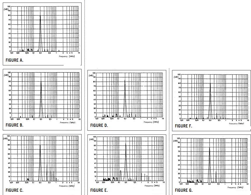
FIGURE A.
FIGURE B.
FIGURE D.
FIGURE F.
FIGURE C.
FIGURE E.
FIGURE G.
The unfortunate absence of the high harmonics and the fourth (800Hz) is due to the special patented output transformer design.
h) Amplifier 8 is well known for its musicality and particular suitability to reproducing classical music; here again, each harmonic is reproduced with a regular rate of decay. Despite the high level of the second harmonic, the subjective level of distortion is very low and the design sounds better than no. 7.
i) Amplifier 9 has no second harmonic, and the others are badly distributed, particularly the third at 600Hz. Feed back and a circuit compensating for distortion in the output valves could not suppress this. The middle and high frequencies are very unpleasant and sound very distorted.
j) Amplifier 10 is a single stage amplifier without feedback, using PX4 tri odes with direct heating (these valves were used in the first Mullard circuit of 1934). Due to the exception al reproduction of the harmonics, the amplifier has a reputation for great musicality. You may also notice the slight "purring" due to the direct heating at 4V AC of the output valve.
Despite the 2% distortion level, this amplifier has little subjective feeling of distortion; the reproduction of the sound of violins, guitars, harpsichords, and voices has an impressive reality and purity.
k) This is also amplifier 10, but this time with a 6dB feedback. Although the distortion meter and graph shows an apparent improvement, there is a subjective feeling of loss in the middle and high frequencies; the high and evenly-degraded harmonics have disappeared.
l) Amplifier 11 is also a single stage design using the WE300B (USA) valve, which is considered by aficionados to be the ultimate triode. Harmonic spectrum analysis shows excellent regularity in the production of each successive harmonic. A violin, in particular, is reproduced very well as harmonics 2 to 20 pass without interference in their relative levels, where as an amplifier of type 2 would truncate many of these, absorbing them in feedback.
POSTSCRIPT
La Nouvelle Revue du Son (successor to the respected Revue du Son) has recently been publishing reviews of "vintage" amplifiers. These have included English classics such as the Quad II and Leak Stereo 60, and incorporate a modified version of Hiraga's test. It is important to note that the test conditions are somewhat different from the above and direct comparison is not possible: the power level used was 10W; the fundamental frequency 1kHz, and the fundamental is not shown in the graphs.
m) Quad II. The very even spectrum may account for the excellent subjective qualities of this amplifier. The even harmonics are more prominent than the odd harmonics, but this is prefer able to the converse. Noise products may be seen in the 10-15kHz region. 1kHz 10W.
n) Leak Stereo 60. The even harmonics are consistently lower than the odd harmonics. This could account for the slightly hard sound that this amplifier gives. 1kHz 10W.
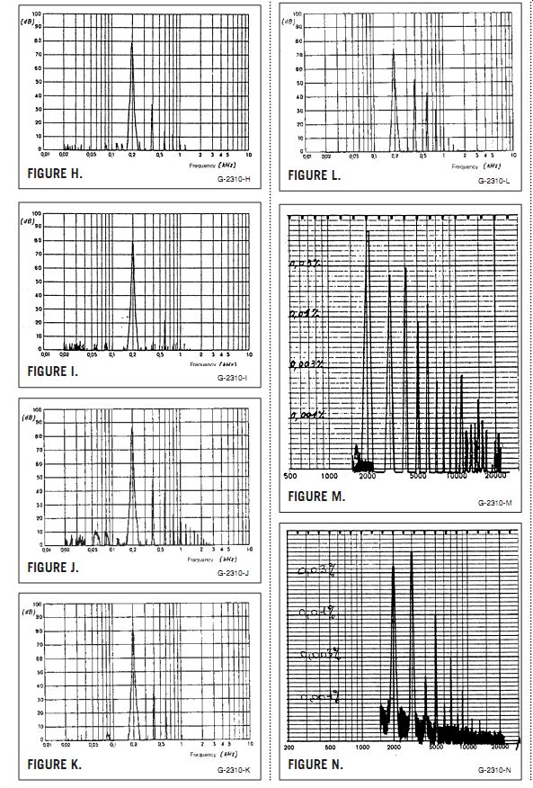
FIGURE M.
FIGURE N.
FIGURE I.
FIGURE J.
FIGURE K.
FIGURE L.
FIGURE H.
------------------
Also see: FRYKLEANER: AN AUDIO BURN-IN GENERATOR